Optical unidirectional amplification in a three-mode optomechanical system
Abstract
We study the directional amplification of an optical probe field in a three-mode optomechanical system, where the mechanical resonator interacts with two linearly-coupled optical cavities and the cavities are driven by strong optical pump fields. The optical probe field is injected into one of the cavity modes, and at the same time, the mechanical resonator is subject to a mechanical drive with the driving frequency equal to the frequency difference between the optical probe and pump fields. We show that the transmission of the probe field can be amplified in one direction and de-amplified in the opposite direction. This directional amplification or de-amplification results from the constructive or destruction interference between different transmission paths in this three-mode optomechanical system.
pacs:
42.50.Wk, 42.50.Ex, 07.10.Cm, 11.30.ErI Introduction
With the rapid development of microfabrication technology, cavity optomechanical system Kippenberg ; Aspelmeyer1 ; Meystre ; Aspelmeyer3 is becoming an appealing candidate to connect a broad spectrum of photonic, electronic, and atomic devices, besides being studied for fundamental questions of macroscopic systems in the quantum limit Vitali . Recently, enormous progresses have been achieved that aim at the applications of optomechanical systems in ultra-high precision measurement Rugar ; Krause ; Regal ; Teufel ; Forstner ; Xu ; Arvanitaki , quantum information processing Mancini , quantum illumination Barzanjeh to optomechanically induced transparency OMIT1 ; OMIT2 ; OMIT3 ; OMIT4 ; OMIT5 ; OMslowlight1 ; OMslowlight2 , absorption OMIA1 ; OMIA2 , and amplification OMAmplification1 ; OMAmplification2 ; OMAmplificationJia ; OMAmplificationXu ; OMAmplificationSSi .
Among these applications, nonreciprocal transmission and amplification are of great interest in the study of the quantum analogue of photonic and electronic devices, such as diode, circulator, and transistor, which are crucial for scalable quantum information processing in integrated circuits Haus . In the past, nonreciprocal devices have been investigated broadly in optical systems Faraday ; ParametricModulation1 ; ParametricModulation2 ; ParametricModulation3 ; ParametricModulation4 ; Chang ; Tang ; Chiral ; Lecocq . In these devices, the occurrence of nonreciprocal light propagation is associated with the symmetry breaking induced by various mechanisms, such as magneto-optical Faraday effect Faraday , parametric modulation ParametricModulation1 ; ParametricModulation2 ; ParametricModulation3 ; ParametricModulation4 , optical nonlinearity Chang ; Tang , and chiral light-matter interaction Chiral .
In recent years, it has been shown that the optomechanical system can be utilized to realize nonreciprocal effects for propagating light fields Manipatruni ; Hafezi ; shen ; Kim ; Fang . The nonreciprocal optical diodes are achieved in multi-mode optomechanical systems with effective breaking of time-reversal symmetry generated by on-demand gauge-invariant phases XXW ; XXW2 ; Tian ; Metelmann ; YLZhang . Nonreciprocal phenomena with directional amplification have been explored theoretically in general coupled-mode systems Ranzani . The phenomena of optical directional amplification have also been implemented experimentally very recently in multi-mode optomechanical systems Ruesink ; Mohammad ; Bernier ; Peterson ; Malz .
In this paper, we study a scheme to achieve directional amplification of an optical probe field in a three-mode optomechanical system, where a mechanical resonator is coupled to two optical modes that directly interact with each other. In this system, controllable phase difference between the linearized optomechanical couplings, which breaks the time-reversal symmetry of this three-mode system, is generated by the strong pump fields on the optical cavities. Meanwhile, the probe field is applied to one of the cavities and the mechanical resonator is subject to a mechanical drive with the driving frequency equal to the frequency difference between the optical probe and pump fields. The constructive (destructive) interference between the transmission paths for the optical probe field and its mechanical counterpart via the optomechanical interaction results in the amplification of the probe field OMAmplificationJia . Strong directional amplification of the optical field with high amplification ratio can be achieved in this system. In comparison with the previous works Ruesink ; Mohammad ; Bernier ; Peterson ; Malz in multi-mode optomechanical systems, where the directional amplification results from the blue-detuned pump fields, here we use the red-detuned pump fields as well as the additional mechanical drive to achieve the optical directional amplification in a three-mode optomechanical system. Since the blue-detuned (red-detuned) pump field will heat (cool) the motion of mechanical resonator in an optomechanical system, our scheme avoiding pumping with blue-detuned light can improve the stability of the amplification scheme in optomechanical systems. As a tradeoff, the additional mechanical drive with the driving frequency equal to the frequency difference between the optical probe and pump fields is required to achieve the directional amplification in our scheme. Our work provides an alternative method to achieve the optical directional amplification in optomechanical systems, which could stimulate future studies of optomechanical interfaces in the implementation of nonreciprocal and nonlinear photonic devices.
This paper is organized as follows. In Sec. II, we present the Hamiltonian of the three-mode optomechanical system for nonreciprocal amplification and our derivation of the transmission coefficients in this system. Details of the directional amplification and de-amplification of the optical probe field are studied in Sec. III. Conclusions are given in Sec. IV.
II Model and transmission matrix

The optomechanical system under consideration consists of a mechanical oscillator with resonance frequency and two optical cavities with resonance frequencies and , respectively, as illustrated in Fig. 1. We first focus on the case that the probe field is incident from the left side to the cavity 1. The total Hamiltonian of this system has the form
| (1) |
The first term describes the free Hamiltonian of the cavity modes and the mechanical one with ()
| (2) |
where () for and () are the creation (annihilation) operators for the cavity modes and the mechanical one. The second term
| (3) |
characterizes the linear coupling between the cavity modes with coupling strength and the radiation-pressure force interaction between the cavities and the mechanical resonator with single-photon coupling strength . The third term describes the mechanical drive, the optical pump fields on the cavities, and the probe field (incident from the left side to cavity 1, see the thin solid arrow in Fig. 1)
| (4) | |||||
where is the frequency, is the amplitude, and is the phase of the two pump fields, () is the frequency and () is the amplitude of the probe field on cavity (the mechanical drive applied on the mechanical resonator). It is worth pointing out that the mechanical drive can be easily realized in experiments through an external electric drive Rugar1 ; Okamoto ; Faust ; Fu . Here without loss of generality, we have assumed that , , and are real numbers.
In the rotating frame with respect to the frequency of the pump fields, the quantum Langevin equations (QLEs) for the operators in the system are given by
| (5) | |||||
| (6) | |||||
| (7) |
Here () are the optical detunings of the cavities, () are the decay rates of the two cavities (mechanical resonator), () are the noise operators of the cavities (mechanical mode) with .
We first derive the steady-state solution of the three-mode system under strong pump fields. Neglecting the effects of the optical probe field and mechanical drive, we can obtain the steady-state solution as
| (8) | |||||
| (9) | |||||
| (10) |
where () are the steady-state averages of the cavities (mechanical mode), and () are the cavity detunings shifted by the radiation-pressure force. These equations are coupled to each other and can be solved self-consistently.
Each operator of this system can be written as a sum of the steady-state solution and its fluctuation with and , where are the fluctuations of the cavities and is that of the mechanical mode. Neglecting the nonlinear terms in the radiation-pressure interaction in Eqs. (8)-(10), we obtain a set of linear QLEs for the fluctuation operators:
| (11) | |||||
| (12) | |||||
| (13) | |||||
where () represent the pump-enhanced linear optomechanical couplings.
In what follows, we fix in our scheme, i.e., the frequency of the mechanical drive is always equal to the frequency difference between the optical probe and pump fields. To solve the above QLEs, we transform all the operators to another rotating frame with , , , and . In addition, we assume that the cavities are driven by the red-detuned pump fields and . In this case, by using the rotating-wave approximation, one can neglect the fast-oscillating counter-rotating terms and obtain the following linearized QLEs
| (14) | |||||
| (15) | |||||
| (16) |
with and . Here and are the detunings in the new rotating frame. The optical response of the cavities to the probe field can be obtained by solving the steady state of Eqs. (14)-(16). By setting , we have
| (17) | |||||
| (18) | |||||
| (19) |
The cavity output fields () can be derived from the input-output theorem with
| (20) |
where represents the cavity loss related to coupling between the cavity and the input (output) modes, and is part of the total cavity loss rate with and . For simplicity of discussion, we focus on the case of over-coupled cavities with and neglect cavity intrinsic dissipation Cai ; Spillane ; Tian2015 . With this assumption, , . The input field on the mechanical resonator can then be written in terms of the cavity input with . The transmission coefficient that describes the dependence of the output field of cavity on the input field can be defined as
| (21) |
With Eqs. (18) and (20), we derive
| (22) |
where we have defined the amplitude of the mechanical drive through ().
Similarly, we can derive the transmission coefficient for a probe field applied to cavity from the right side (see the thin dashed arrow in Fig. 1). In this case, we have , , and still fix . Here the transmission coefficient is defined as . We derive that
| (23) |
This equation shows that the propagation of the optical probe field in the three-mode optomechanical system depends strongly on the interference between various paths of the probe field via the optical cavity with amplitude and the frequency-matched mechanical drive with amplitude via the optomechanical interaction. And the transmission is not symmetric between cavities and .
III Directional amplification of optical probes
In this section, we will study the transmission of optical probe and the asymmetry in the transmission systematically. We will show that amplification of optical probe fields can be directional. Consider and for simplicity of discussion. The transmission coefficients can be rewritten as
| (24) |
and
| (25) |
When (), the model reduces to that studied in XXW , where the directional transmission of the probe field can be achieved under optimal parameters. In such a scheme, the introduction of the nontrivial phase breaks the time-reversal symmetry of this system and results in nonreciprocal propagation of the probe field. In contrast, in the presence of the frequency-matched mechanical drive and in the absence of the second cavity ( and ), the system reduces to a standard two-mode optomechanical system. In this case, it was shown that the presence of the mechanical drive leads to the amplification of the output field OMAmplificationJia . The amplification and enhancement in energy arise from the phonon-photon parametric process in the presence of the frequency-matched mechanical drive.

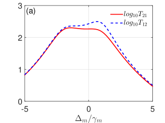
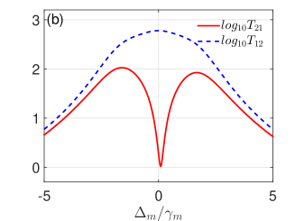
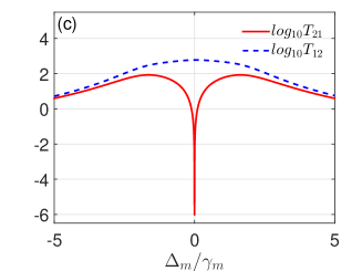
Now we study the effect of the frequency-matched mechanical drive on the propagation of the probe field in the three-mode optomechanical system in the general case of and . In Fig. 2, we plot the probability of the transmission and as functions of at different values of the phases and . We observe that in general, the transmission of the probe field is asymmetric with , and or can be much larger than . This result indicates nonreciprocity with amplification of the optical probe field. In particular, at certain optimal values of and , e.g., , , and , as shown in Figs. 2(c). The transmission from cavity to cavity is strongly amplified; whereas, the transmission on the opposite direction is suppressed. In this case, the amplification of the probe field results from phonon-photon parametric process due to the existence of the frequency-matched mechanical drive OMAmplificationJia .
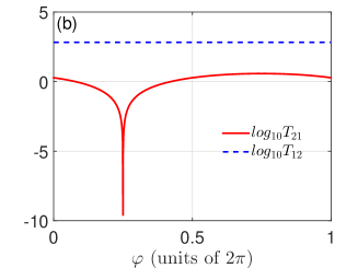
We plot the probability of the transmission and as functions of and in Fig. 3. It is also shown that the directional propagation can be achieved with in Fig. 3(a) or in Fig. 3(b). Note that, when with other parameters given in the caption of Fig. 3(b), the probability of transmission is independent of , which can be given through Eq. (25).
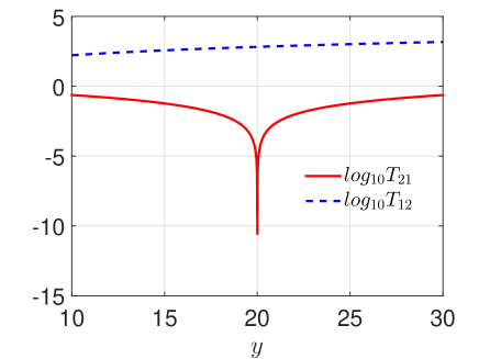
To further understand the effect of the frequency-matched mechanical drive on the transmission property of the probe field, we assume that the parameters , , , and . Then the corresponding transmission coefficients and are simplified to be
| (26) | |||||
| (27) |
In the absence of the mechanical drive (), the directional transmission of the probe field can occur with and (particularly, at ) as shown in XXW . On the contrary, in the presence of frequency-matched mechanical drive with and , we have and . The directional amplification of the optical probe field can be observed due to the presence of the mechanical drive frequency-matched to the probe field, and the direction of the amplification is opposite to that in the case of directional transmission in XXW . Strong amplification requires , i.e., the cavity damping rate is approximately equal to the mechanical damping rate .
To study the role of the mechanical drive, we plot and as functions of in Fig. 4. This plot clearly demonstrates that the propagation of the optical field is strongly amplified with when the mechanical drive becomes large (). Meanwhile, when under the parameters given in the caption of Fig. 4, the transmission in the opposite direction quickly drops with .
IV Conclusions
To conclude, we investigate the transmission of an optical probe field in a three-mode optomechanical system, where the mechanical resonator is subject to a mechanical drive with the driving frequency being equal to the frequency difference between the optical probe and pump fields. Under appropriate parameters, the directional amplification of the probe field resulting from the interference between different optical path and phonon-photon parametric process can be achieved. Amplification far exceeding unity can be achieved when the mechanical drive becomes strong. Such optomechanical setups could be used to switch and amplify weak probe signals in quantum networks.
Acknowledgements.
National Natural Science Foundation of China (with Grants. No. 11422437, No. 11505126, No. 11534002, No. 11421063, No. U1530401); Postdoctoral Science Foundation of China (with Grant No. 2016M591055); PhD research startup foundation of Tianjin Normal University (with Grant. No. 52XB1415); National Science Foundation (NSF) (with Grants. No. DMR-0956064 and No. PHY-1720501); UC Multicampus-National Lab Collaborative Research and Training (with Grant No. LFR-17-477237).References
- (1) T. J. Kippenberg and K. J. Vahala, “Cavity optomechanics: back-action at the mesoscale,” Science 321(5893), 1172–1176 (2008).
- (2) M. Aspelmeyer, P. Meystre, and K. C. Schwab, “Quantum optomechanics,” Phys. Today 65(7), 29–35 (2012).
- (3) P. Meystre, “A short walk through quantum optomechanics,” Ann. Phys. (Berlin) 525(3), 215–233 (2013).
- (4) M. Aspelmeyer, T. J. Kippenberg, and F. Marquardt, “Cavity optomechanics,” Rev. Mod. Phys. 86(4), 1391 (2014).
- (5) D. Vitali, S. Gigan, A. Ferreira, H. R. Böhm, P. Tombesi, A. Guerreiro, V.Vedral, A. Zeilinger, and M. Aspelmeyer, “Optomechanical entanglement between a movable mirror and a cavity field,” Phys. Rev. Lett. 98(3), 030405 (2007).
- (6) D. Rugar, R. Budakian, H. J. Mamin, and B. W. Chui, “Single spin detection by magnetic resonance force microscopy,” Nature (London) 430(6997), 329–332 (2004).
- (7) A. G. Krause, M. Winger, T. D. Blasius, Q. Lin, and O. Painter, “A high-resolution microchip optomechanical accelerometer,” Nat. Photon. 6(11), 768–772 (2012).
- (8) C. A. Regal, J. D. Teufel, and K. W. Lehnert, “Measuring nanomechanical motion with a microwave cavity interferometer,” Nat. Phys. 4(7), 555–560 (2008).
- (9) J. D. Teufel, T. Donner, M. A. Castellanos-Beltran, J. W. Harlow, and K. W. Lehnert, “Nanomechanical motion measured with an imprecision below that at the standard quantum limit,” Nat. Nanotechnol. 4(12), 820–823 (2009).
- (10) S. Forstner, S. Prams, J. Knittel, E. D. van Ooijen, J. D. Swaim, G. I. Harris, A. Szorkovszky, W. P. Bowen, and H. Rubinsztein-Dunlop, “Cavity optomechanical magnetometer,” Phys. Rev. Lett. 108(12), 120801 (2012).
- (11) X. Xu and J. M. Taylor, “Squeezing in a coupled two-mode optomechanical system for force sensing below the standard quantum limit,” Phys. Rev. A 90(4), 043848 (2014).
- (12) A. Arvanitaki and A. A. Geraci, “Detecting high-frequency gravitational waves with optically levitated sensors,” Phys. Rev. Lett. 110(7), 071105 (2013).
- (13) S. Mancini, D. Vitali, and P. Tombesi, “Scheme for teleportation of quantum states onto a mechanical resonator,” Phys. Rev. Lett. 90(13), 137901 (2003).
- (14) Sh. Barzanjeh, S. Guha, C. Weedbrook, D. Vitali, J. H. Shapiro, and S. Pirandola, “Microwave quantum illumination,” Phys. Rev. Lett. 114(8), 080503 (2015).
- (15) G. S. Agarwal and S. Huang, “Electromagnetically induced transparency in mechanical effects of light,” Phys. Rev. A 81(4), 041803 (2010).
- (16) S. Weis, R. Rivière, S. Deléglise, E. Gavartin, O. Arcizet, A. Schliesser, and T. J. Kippenberg, “Optomechanically induced transparency,” Science 330(6010), 1520–1523 (2010).
- (17) J. D. Teufel, D. Li, M. S. Allman, K. Cicak, A. J. Sirois, J. D. Whittaker, and R. W. Simmonds, “Circuit cavity electromechanics in the strong-coupling regime,” Nature (London), 471(7337), 204–208 (2011).
- (18) A. H. Safavi-Naeini, T. P. M. Alegre, J. Chan, M. Eichenfield, M. Winger, Q. Lin, J. T. Hill, D. E. Chang, and O. Painter, “Electromagnetically induced transparency and slow light with optomechanics,” Nature (London) 472(7341), 69–73 (2011).
- (19) M. Karuza, C. Biancofiore, M. Bawaj, C. Molinelli, M. Galassi, R. Natali, P. Tombesi, G. Di Giuseppe, and D. Vitali, “Optomechanically induced transparency in a membrane-in-the-middle setup at room temperature,” Phys. Rev. A 88(1), 013804 (2013).
- (20) X. Zhou, F. Hocke, A. Schliesser, A. Marx, H. Huebl, R. Gross, and T. J. Kippenberg, “Slowing, advancing and switching of microwave signals using circuit nanoelectromechanics,” Nat. Phys. 9(3), 179–184 (2013).
- (21) D. E. Chang, A. H. Safavi-Naeini, M. Hafezi, and O. Painter, “Slowing and stopping light using an optomechanical crystal array,” New J. Phys. 13(2), 023003 (2011).
- (22) F. Hocke, X. Zhou, A. Schliesser, T. J. Kippenberg, H. Huebl, and R. Gross, “Electromechanically induced absorption in a circuit nano-electromechanical system,” New J. Phys. 14(12), 123037 (2012).
- (23) K. Qu and G. S. Agarwal, “Phonon-mediated electromagnetically induced absorption in hybrid opto-electromechanical systems,” Phys. Rev. A 87(3), 031802 (2013).
- (24) F. Massel, T. T. Heikkilä, J.-M. Pirkkalainen, S. U. Cho, H. Saloniemi, P. J. Hakonen, and M. A. Sillanpää, “Microwave amplification with nanomechanical resonators,” Nature (London) 480(7377), 351–354 (2011).
- (25) A. Metelmann and A. A. Clerk, “Quantum-limited amplification via reservoir engineering,” Phys. Rev. Lett. 112(13), 133904 (2014).
- (26) W. Z. Jia, L. F. Wei, Y. Li, and Y. X. Liu, “Phase-dependent optical response properties in an optomechanical system by coherently driving the mechanical resonator,” Phys. Rev. A 91(4), 043843 (2015).
- (27) X.-W. Xu and Y. Li, “Controllable optical output fields from an optomechanical system with mechanical driving,” Phys. Rev. A 92(2), 023855 (2015).
- (28) L.-G. Si, H. Xiong, M. S. Zubairy, and Y. Wu, “Optomechanically induced opacity and amplification in a quadratically coupled optomechanical system,” Phys. Rev. A 95, 033803 (2017).
- (29) H. A. Haus, Waves and Fields in Optoelectronics (Prentice-Hall, Englewood Cliffs, NJ, 1984).
- (30) L. Bi, J. Hu, P. Jiang, D. H. Kim, G. F. Dionne, L. C. Kimerling, and C. A. Ross, “On-chip optical isolation in monolithically integrated non-reciprocal optical resonators,” Nat. Photon. 5(12), 758–762 (2011).
- (31) Z. Yu and S. Fan, “Complete optical isolation created by indirect interband photonic transitions,” Nat. Photon. 3(2), 91–94 (2009).
- (32) D. W. Wang, H. T. Zhou, M. J. Guo, J. X. Zhang, J. Evers, and S. Y. Zhu, “Optical diode made from a moving photonic crystal,” Phys. Rev. Lett. 110(9), 093901 (2013).
- (33) S. A. R. Horsley, J.-H. Wu, M. Artoni, and G. C. La Rocca, “Optical nonreciprocity of cold atom Bragg mirrors in motion,” Phys. Rev. Lett. 110(22), 223602 (2013).
- (34) N. A. Estep, D. L. Sounas, J. Soric, and A. Alù, “Magnetic-free non-reciprocity and isolation based on parametrically modulated coupled-resonator loops,” Nat. Phys. 10(12), 923–927 (2014).
- (35) L. Chang, X. Jiang, S. Hua, C. Yang, J. Wen, L. Jiang, G. Li, G. Wang, and M. Xiao, “Parity-time symmetry and variable optical isolation in active-passive-coupled microresonators,” Nat. Photon. 8(7), 524–529 (2014).
- (36) X. Guo, C.-L. Zou, H. Jung, and H. X. Tang, “On-chip strong coupling and efficient frequency conversion between telecom and visible optical modes,” Phys. Rev. Lett. 117(12), 123902 (2016).
- (37) I. Söllner, S. Mahmoodian, S. L. Hansen, L. Midolo, A. Javadi, G. Kiršanskė, T. Pregnolato, H. El-Ella, E. H. Lee, J. D. Song, Søren Stobbe, and P. Lodahl , “Deterministic photon–emitter coupling in chiral photonic circuits,” Nat. Nanotechnol. 10(9), 775–778 (2015).
- (38) F. Lecocq, L. Ranzani, G. A. Peterson, K. Cicak, R. W. Simmonds, J. D. Teufel, and J. Aumentado, “Nonreciprocal microwave signal processing with a field-programmable Josephson amplifier,” Phys. Rev. Applied 7(2), 024028 (2017).
- (39) S. Manipatruni, J. T. Robinson, and M. Lipson, “Optical nonreciprocity in optomechanical structures,” Phys. Rev. Lett. 102(21), 213903 (2009).
- (40) M. Hafezi and P. Rabl, “Optomechanically induced non-reciprocity in microring resonators,” Opt. Express 20(7), 7672–7684 (2012).
- (41) Z. Shen, Y.-L. Zhang, Y. Chen, C.-L. Zou, Y.-F. Xiao, X.-B. Zou, F.-W. Sun, G.-C. Guo, and C.-H. Dong, “Experimental realization of optomechanically induced non-reciprocity,” Nat. Photon. 10(10), 657–661 (2016).
- (42) J. Kim, M. C. Kuzyk, K. Han, H. Wang, and G. Bahl, “Non-reciprocal Brillouin scattering induced transparency,” Nat. Phys. 11(3), 275–280 (2015).
- (43) K. Fang, J. Luo, A. Metelmann, M. H. Matheny, F. Marquardt, A. A. Clerk, and O. Painter, “Generalized nonreciprocity in an optomechanical circuit via synthetic magnetism and reservoir engineering,” Nat. Phys. 13, 465 (2017).
- (44) X. W. Xu and Y. Li, “Optical nonreciprocity and optomechanical circulator in three-mode optomechanical systems,” Phys. Rev. A 91(5), 053854 (2015).
- (45) X. W. Xu, Y. Li, A. X. Chen, and Y. X. Liu, “Nonreciprocal conversion between microwave and optical photons in electro-optomechanical systems,” Phys. Rev. A 93(2), 023827 (2016).
- (46) L. Tian and Z. Li, “Nonreciprocal state conversion between microwave and optical Photons,” arXiv: 1610.09556 (2016).
- (47) A. Metelmann, and A. A. Clerk, “Nonreciprocal photon transmission and amplification via reservoir engineering,” Phys. Rev. X 5(2), 021025 (2015).
- (48) Y. L. Zhang, C. H. Dong, C. L. Zou, X. B. Zou, Y. D. Wang, and G. C. Guo, “Optomechanical devices based on traveling-wave microresonators,” Phys. Rev. A 95(4), 043815 (2017).
- (49) L. Ranzani, and J. Aumentado, “Graph-based analysis of nonreciprocity in coupled-mode systems,” New J. Physics, 17(2), 023024 (2015).
- (50) G. A. Peterson, F. Lecocq, K. Cicak, R. W. Simmonds, J. Aumentado, and J. D. Teufel, “Demonstration of efficient nonreciprocity in a microwave optomechanical circuit,” arXiv: 1703.05269.
- (51) D. Malz, L. D. Toth, N. R. Bernier, A. K. Feofanov, T. J. Kippenberg, and A. Nunnenkamp, “Quantum-limited directional amplifiers with optomechanics,” arXiv: 1705.00436.
- (52) F. Ruesink, M. A. Miri, A. Alù, and E. Verhagen, “Nonreciprocity and magnetic-free isolation based on optomechanical interactions,” Nat. Commun. 7, 13662 (2016).
- (53) M. A. Miri, F. Ruesink, E. Verhagen, and A. Alù, “Fundamentals of optical non-reciprocity based on optomechanical coupling,” Phys. Rev. Applied 7(6), 064014 (2017).
- (54) N. R. Bernier, L. D. Tóth, A. Koottandavida, M. Ioannou, D. Malz, A. Nunnenkamp, A. K. Feofanov, and T. J. Kippenberg, “Nonreciprocal reconfigurable microwave optomechanical circuit,” arXiv: 1612.08223 (2016).
- (55) D. Rugar and P. Grütter, “Mechanical parametric amplification and thermomechanical noise squeezing,” Phys. Rev. Lett. 67(6), 699 (1991).
- (56) H. Okamoto, A. Gourgout, C. Y. Chang, K. Onomitsu, I. Mahboob, E. Y. Chang, and H. Yamaguchi, “Coherent phonon manipulation in coupled mechanical resonators,” Nat. Phys. 9(8), 480–484 (2013).
- (57) T. Faust, J. Rieger, M. J. Seitner, J. P. Kotthaus, and E. M. Weig, “Coherent control of a classical nanomechanical two-level system,” Nat. Phys. 9(8), 485–488 (2013).
- (58) H. Fu, Z. Gong, T. Mao, C. Sun, S. Yi, Y. Li, and G. Cao, “Classical analog of Stückelberg interferometry in a two-coupled-cantilever Cbased optomechanical system,” Phys. Rev. A 94(4), 043855 (2016).
- (59) M. Cai, O. J. Painter, and K. J. Vahala, “Observation of critical coupling in a fiber taper to a silica-microsphere whispering-gallery mode system,” Phys. Rev. Lett. 85(1), 74 (2000).
- (60) S. M. Spillane, T. J. Kippenberg, O. J. Painter, and K. J. Vahala, “Ideality in a fiber-taper-coupled microresonator system for application to cavity quantum electrodynamics,” Phys. Rev. Lett. 91(4), 043902 (2003).
- (61) L. Tian, “Optoelectromechanical transducer: Reversible conversion between microwave and optical photons,” Ann. Phys. (Berlin) 527(1-2), 1–14 (2015).