Model-based Catheter Segmentation in MRI-images
Abstract
Accurate and reliable segmentation of catheters in MR-guided interventions remains a challenge, and a step of critical importance in clinical workflows. In this work, under reasonable assumptions, mechanical model based heuristics guide the segmentation process allows correct catheter identification rates greater than 98% (error2.88 mm), and reduction in outliers to one-fourth compared to the state of the art. Given distal tips, searching towards the proximal ends of the catheters is guided by mechanical models that are estimated on a per-catheter basis. Their bending characteristics are used to constrain the image feature based candidate points. The final catheter trajectories are hybrid sequences of individual points, each derived from model and image features. We evaluate the method on a database of 10 patient MRI scans including 101 manually segmented catheters. The mean errors were 1.40 mm and the median errors were 1.05 mm. The number of outliers deviating more than 2 mm from the gold standard is 7, and the number of outliers deviating more than 3 mm from the gold standard is just 2.
Keywords:
segmentation, identification, catheter, MRI, validation1 Introduction
MRI imaging is a standard component in the tools for diagnosis, biopsy, and treatment of numerous types of cancers [5] due to the superior soft tissue contrast it provides. While MRI scans provide the physician with improved imaging of the tumor and adjacent soft tissue (compared to x-ray, ultrasound, or CT), the artifacts created in these scans by typical catheters are much more difficult to interpret. For instance, artifacts created by catheters with metalic stylets in x-ray or CT scans acquired during pelvic brachytherapy are very distinct and amenable to automatic segmentation using standard image-processing techniques in commercial products such as Oncentra Brachytherapy111Elekta, Stockholm, Sweden and Eclipse222Varian Medical Systems, CA, USA. Today, no corresponding specialized automatic solutions exist for MRI [8, 1].
We believe that in the absence of reliable automatic segmentation tools for this task, MRI-guided catheter-based interventions will not gain mainstream acceptance; manual accomplishment of this task is time consuming, tedious, and error-prone, and requires significant concentration of the operator. We propose a new highly accurate catheter segmentation method based on a search cone [7] and use a benchmark database with a significant number of catheters using different MRI imaging protocols for validation.
2 Related Work
The appearance of catheters in MRI images is influenced by the imaging parameters, susceptibility effects, and the direction of the static magnetic field relative to that of the catheter [8, 1]. Another challenge is posed by varying, deflected catheters caused by different forces interacting with them during insertion into the body. Vesselness measures [2] try to enhance tubular structures such as vessels in the images, but suffer heavily from oversegmentation. In [6] a catheter segmentation method for 2D B-mode ultrasound images using Hough transforms is proposed. For 3D MRI images in [7], a sequence of Fibonacci-sized conical search regions is used. In [3] three catheter models are compared in terms of deflection accuracy measured against a physical experiment.
Here, we based our model based segmentation method on two assumptions: (1) catheters for biopsy and treatment are typically introduced from a firm base (known as template, fixture, or guide); (2) the overall catheter deflection can be approximately modelled by a main force acting on the catheter tip.
3 Methods
Angular Spring Models In [3] the most effective model for the simulation of catheter bending was reported to be the angular spring model. In this approach the catheter is regarded as an array of a finite number of stiff line segments (cantilever rods) connected by angular springs. Following these ideas and simplifying the approach by neglecting model convergence over time for efficiency reasons, we can use the following forward and backward schemes to calculate segment-wise deflection angles , the total deflection angle and segment orthogonal end point forces in 2D. The calculation works either in a forward manner starting from the fixed end (the proximal end of the catheter in our case) or in a backward fashion starting from a given catheter tip for a number of segments ():
| Forward | Backward | |||
|---|---|---|---|---|
| (1) |
where is the physical angular spring stiffness [] of the catheter and is the effective main force acting on the catheter at the tip. The angle describes the total segment angle compared to a non-bent catheter (reference catheter) in the forward and backward simulation. It is easy to see that in the backward simulation starting from the given catheter tip, we need estimates for and orthogonal segment force .
Model Estimation The first step in our new algorithm is the estimation of the angular spring model. For this aim, it is necessary to have a reference catheter direction representing a non-deflected catheter. For many catheter grid based procedures, the reference direction can be inferred using the base (or template) that defines a normal plane which is assumed orthogonal to a straight catheter333The estimation of the normal plane for specific clinical applications can be a topic of investigation on its own. In the case of pelvic brachytherapy with a template grid, four vitamin E capsules implanted in the template create hyperintense artificats in the MR and specify a regression plane for the reference catheter direction.. Given the reference catheter vector with a declination from the SI-axis (z) the segment sum angle for the backward simulation can be estimated from a large catheter segment vector found by distal-proximal ray casting favoring dark lines (see step 1 below for details):
| (2) |
Furthermore, an estimate of the catheter length disregarding bending using distance from the base template plane
| (3) |
is needed, where calculates point distance from a plane.
For the remaining estimation of the deflection
| (4) |
from the tip to the reference catheter in normal direction is estimated.
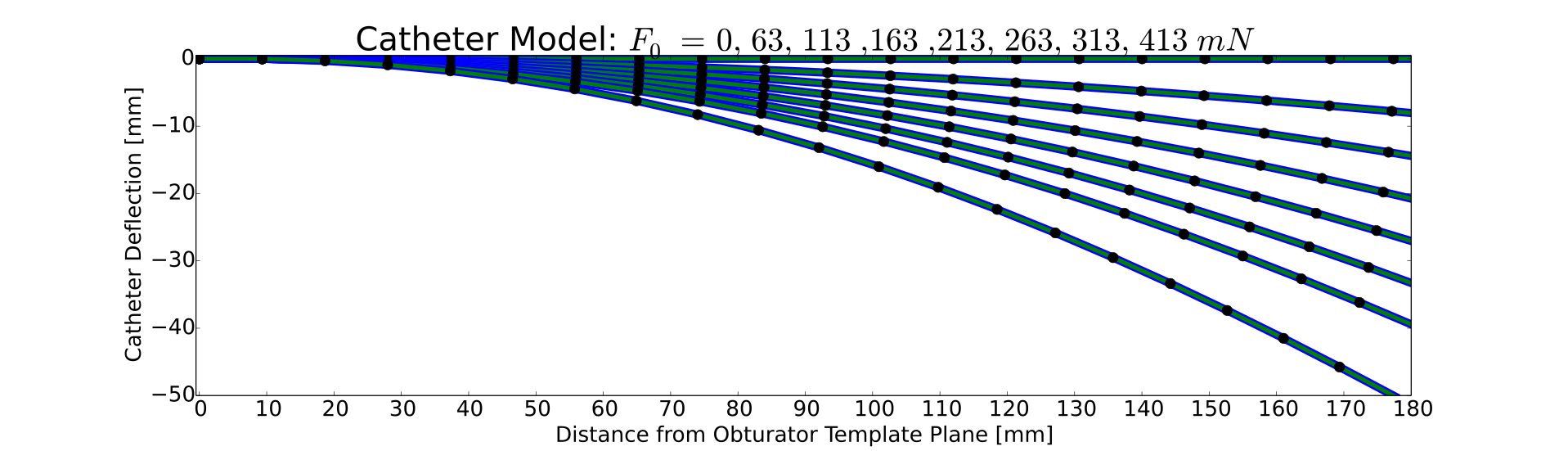
With these parameter estimates, we can compute the remaining model parameter for backward tracking of the catheter model, i.e. a look up in a finely interpolated model table parametrized by and yields . Note, every position between the undeflected and the most deflected catheter has a force value assigned that can be used as . The refined model lookup table calculates Fig. 1 nearly without gaps (100 sample points in each direction). Linear interpolation is used for positions still inbetween supporting -points.
Model Guided Catheter Search Details:
Search cone.
1. Model Initializing First Cone Search In this phase starting from the tip the search cone [7] covers half of the estimated catheter length and searches a first point on the catheter approximately in the middle. A step direction vector helps in the initialization phase. The step is robust and in most cases finds the middle of the catheter as most catheters are rather straight from the tip up to their middle (cf. Fig. 1). The found long segment is the basis for the model estimation phase described above.
Now, the main catheter detection processing starts again from the tip , uses the initialized model as a guide, and works its way using shorter segments towards the proximal end.
First Catheter Point Detection Iteration () While the top of the cone is the given tip position, the base point of the first cone search is derived as and the located point is accepted as . After this step, the first short segment is estimated and allows the definition of the first local segment coordinate system to which the angular spring model can relate.
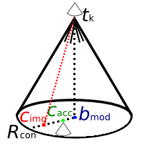
2. Definition of Local Segment Coordinate Systems () With an accepted catheter segment found by ray casting, for each segment a local right-handed coordinate system is set-up coherent to the LPI image directions. They consist of the catheter deflection plane normal defining the 2D -plane for the catheter bending simulation (cf. Fig. 1), deflection direction (cf. ) and reference direction (cf. ). For every iteration, they are newly defined using the last accepted segment vector ( is the top of the current cone, cf. Fig. 2)
| (5) |
This allows the model catheter to deflect in more than one plane and makes the algorithm truly 3D capable. From step to step, the local coordinate systems slightly rotate. For increased efficiency, we also do not need to use more than one spring for the rod joints as proposed in [3].
3. Model-based Cone Search The top point of the cone is a definitely accepted catheter point and the base point defining the center of a circular region as cone base is proposed as follows (cf. Fig. 2): Metrically synchronously to the cone search and subject to the local coordinate system, deflection backward simulation steps take place. Finally, a new model cone base point is proposed adding a model-based step vector to the current cone top resulting in
| (6) |
Here, represents the chosen segment length. If the point found by ray casting inside the search cone at the base fulfills the distance constraint
| (7) |
it is accepted valid as next cone top and added to the list of catheter defining points (see Fig. 2).
Model Constraint Violation Otherwise, if the point found from image features deviates too far from the model proposed base point an acceptable compromise point is generated and inserted into the list of found catheter points:
| (8) |
By this means, the resulting catheter trajectory is a compromise or hybrid between image feature based and model based point proposals.
Image Features Preferred and Final Catheter Definition Catheter trajectories appear as signal voids in MR scans, while the surrounding tissue is brighter. Thus, we use a small circular gradient inspired 2D mask that responds to this pattern and also consider the expected geometry of the catheter cross-sections (diameter). When searching in conic regions by ray casting, we look for distal to proximal line integrals minimizing the image intensity value taking the preferred gradient pattern into account by subtracting it from the sum. Finally, the hybrid model and image feature based points are approximated by a Bezier curve [7] with control points.
4 Experiments
For evaluation we used MR images from ten patients in which 101 catheters were carefully segmented by a medical expert. The MRI scans were acquired using a mix of protocols that include two-dimensional low-artifact T2-weighted Fast Spin Echo (FSE, TR/TE=3000/120 ms, 0.2x0.3x2.0 mm3), three-dimensional FSE (Siemens SPACE, TR/TE=3000/160 ms, 0.4x0.4x1.0 mm3), 3D balanced steady state free precession (3D bSSFP, TR/TE = 5.8/2.9 msec, 0.6x0.6x1.6 mm3). The scanner was a 3 Tesla MRI “Magnetom Verio” (Siemens Healthcare, Erlangen, Germany). The catheters in the images appear as signal voids (dark trajectories) on the T2/FSE images, and are surrounded by prominent so called blooming artifacts in the 3D bSSFP sequence.
The plastic catheters (diameter 1.6 mm or 16 Gauge) have a metallic needle inlay made of tungsten-alloy and an average insertion depth of 74 mm. We use 7 search cones with equal height , =8. Our synchronous catheter model simulation always uses segments for full length (187 mm). We empirically choose Nm as our 16 Gauge catheters are stiffer than those (18 Gauge) presented in [3]. The radius of the cone base circle is set generously to 20 mm to evaluate the model vs. the image features influence.
Three experiments are conducted in this work by varying the tolerance as 0/ mm: (1) “full model” using guidance model points only, (2) “image features only” with fully image feature based points and (3) “trade-off” as a compromise or hybrid mode between model and image features based points as core contribution of this paper.
5 Results
The Hausdorff distance (HD) between the gold standard and automatic segmentations in the patient MR images was evaluated. The HD quantifies the maximal distance between two catheter tubes [4] and thus is a very strict measure which is necessary for evaluation of clinical applicability.
| CO | Med. | MeanStD |
|---|---|---|
| 2 | 1.05 | 1.401.15 |
| 12 | 1.00 | 1.992.79 |
| 37 | 2.39 | 2.751.54 |
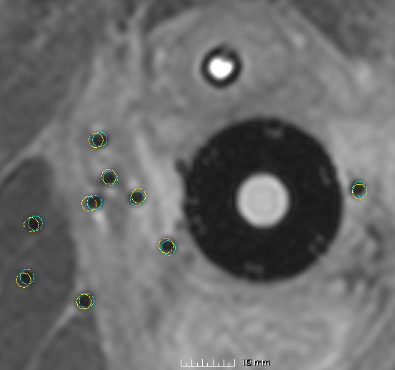
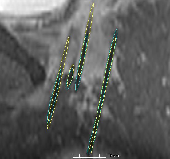
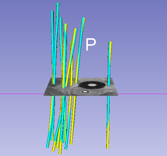
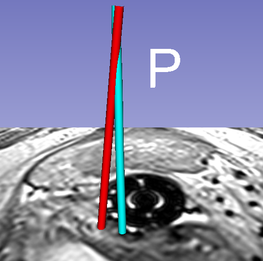
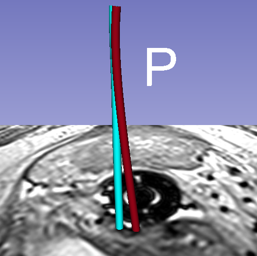
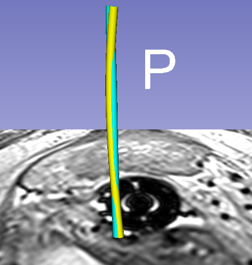
Qualitative results for two different examples can be seen in Fig. 3 and demo movies444https://goo.gl/fLsa2R. The top rows illustrates cross-sectional and 3D rendered views of automated segmentations of a catheter array. The overlap of the colored catheters shows how well they agree. The bottom row of this figure illustrates the case of one particular catheter from the experiments, and specifically how both the model and image guidance are necessary to achieve correct segmentation.
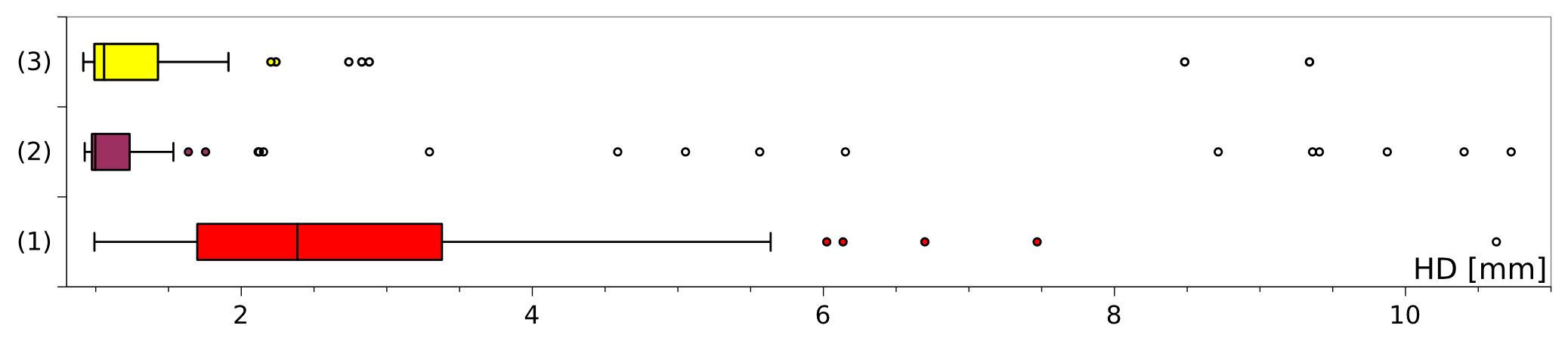
Quantitatively, as can be seen in Fig. 4, comparing experiment (2) and (3) the number of critical outliers (HD3 mm) can be significantly reduced to one sixth. Outliers with 2 mm HD can be reduced from 15 to 7 (53%). For (3), the threshold for the number of outliers to increase from 2 to 3 is 2.88 mm. Regarding (3), the median value that represents the most frequent result in a clinical setting is not significantly higher than for using image features alone (2). Apart from that, using the estimated model alone is not advisable, as the mean/median values as well as the indicators of robustness (standard deviation, quartile ranges) are too high. This is reflected in the statistics: The differences between the results of the experiments are statistically different (Kruskal-Wallis ANOVA on ranks test: ). Tukey post-hoc tests show differences between experiment (1) vs. (2) and (3) to be significant (), while (2) and (3) do not differ. The segmentation time for a single catheter is 2 seconds on an standard Intel i7 3 GHz computer (Python implementation in Slicer555http://www.slicer.org/).
6 Conclusion
The incorporation of our proposed model strongly helps to shift the state of the art in catheter segmentation from MRI [7] towards practical clinically usability by reducing outliers to one-fourth (there 8 needles with HD4 mm).
The proposed model guided catheter segmentation approach (exp. (3)) can reduce the number of outliers with HD3 mm to one sixth, compared to using image features alone (exp. (2)). The number of outliers with HD2 mm can be reduced by half between these two experiments. The benefit of the model is to filter out implausible outliers from the image-based feature points which would cause improbable curvatures in the segmented catheter trajectory. This is an important contribution towards enabling practical clinical acceptance of MRI-guided interventions, a trend that is gaining momentum in recent years.
7 Discussion and Future Work
We have shown that a hybrid strategy is necessary for catheter segmentation from MRI because alone, neither image feature nor model based catheter point estimations, delivers consistently correct results. The initialization of the model is an area that needs further investigation, especially regarding more bent cath-eters.
References
- [1] SP DiMaio, DF Kacher, RE Ellis, G Fichtinger, N Hata, GP Zientara, LP Panych, R Kikinis, and FA Jolesz. Needle artifact localization in 3t mr images. Studies in Health Technology and Informatics, 119:120, 2005.
- [2] K Drechsler and CO Laura. Comparison of vesselness functions for multiscale analysis of the liver vasculature. In Information Technology and Applications in Biomedicine (ITAB), 2010 10th IEEE International Conference on, pages 1–5, Nov 2010.
- [3] O Goksel, E Dehghan, and S Salcudean. Modeling and simulation of flexible needles. Medical Engineering & Physics, 31(9):1069–1078, 2009.
- [4] DP Huttenlocher, GA Klanderman, and WJ Rucklidge. Comparing images using the hausdorff distance. Pattern Analysis and Machine Intelligence, IEEE Transactions on, 15(9):850–863, Sep 1993.
- [5] FA Jolesz. Intraoperative Imaging and Image-Guided Therapy. Springer Science & Business Media, 2014.
- [6] SH Okazawa, R Ebrahimi, J Chuang, RN Rohling, and SE Salcudean. Methods for segmenting curved needles in ultrasound images. Medical Image Analysis, 10(3):330 – 342, 2006. Special Issue on The Second International Workshop on Biomedical Image Registration (WBIR’03).
- [7] G Pernelle, A Mehrtash, L Barber, A Damato, W Wang, RT Seethamraju, E Schmidt, A. Cormack, R, W Wells, A Viswanathan, and T Kapur. Validation of catheter segmentation for mr-guided gynecologic cancer brachytherapy. In Kensaku Mori, Ichiro Sakuma, Yoshinobu Sato, Christian Barillot, and Nassir Navab, editors, Medical Image Computing and Computer-Assisted Intervention - MICCAI 2013, volume 8151 of Lecture Notes in Computer Science, pages 380–387. Springer Berlin Heidelberg, 2013.
- [8] SE Song, NB Cho, II Iordachita, P Guion, Fichtinger G, A Kaushal, K Camphausen, and LL Whitcomb. Biopsy catheter artifact localization in mri-guided robotic transrectal prostate intervention. IEEE Trans Biomed Eng, 59(7):1902–11, 2012.