Feasibility of the optical fiber clock
Abstract
We explore the feasibility of a fiber clock, a compact high-precision optical lattice atomic clock based on atoms trapped inside hollow core optical fiber. Such setup offers an intriguing potential for both substantially increased number of interrogated atoms and miniaturization. We evaluate the sensitivity of the - clock transition in Hg and other divalent atoms to the fiber inner core surface at non-zero temperatures. The Casimir-Polder interaction induced - transition frequency shift is calculated for the atom inside the hollow capillary as a function of atomic position, capillary material, and geometric parameters. For atoms on the axis of a silica capillary with inner radius and optimally chosen thickness , the atom-surface interaction induced - clock transition frequency shift can be kept on the level . We also estimate the atom loss and heating due to the collisions with the buffer gas, lattice intensity noise induced heating, spontaneous photon scattering, and residual birefringence induced frequency shifts.
pacs:
37.10.De, 37.10.Gh, 42.50.WkI Introduction
The rapid progress in micro- and nano-fabrication technologies and advances in material science together with the growing demand for precision metrology and quantum information processing gave rise to a new branch of research engineering aiming to develop miniaturized quantum devices. Examples include atomic clocks Treutlein et al. (2004); Ramírez-Martínez et al. (2011); Deutsch et al. (2010); Gerritsma et al. (2007), atomic sensors, interferometers Griffith et al. (2010); Lust and Youngner (2008); Abbink et al. (2007); Eklund et al. (2008); Wang et al. (2005), and quantum logic gates Schulz (2009). In particular, development of miniaturized atomic clocks is anticipated to enable important applications requiring portability and low power consumption, such as secure telecommunications Fröhlich and Yuan (2015); Cartwright (2013), mobile timing, navigation Langley (1991); Kitching (2007); Krawinkel and Schön (2016), and deep space atomic clocks Ely et al. (2014).
The main platforms for compact quantum devices are micro-electromechanical systems Knappe (2008); Kishimoto et al. (2006), miniaturized wire traps Fortagh et al. (1998), and, more recently, hollow core optical fibers Cregan et al. (1999); Okaba et al. (2014). Here we analyze the feasibility of a “fiber clock”—a device that holds interrogated clock atoms inside a hollow core optical fiber. The atoms are optically trapped, avoiding collisions with the wall surface Okaba et al. (2014). The “fiber clock” is a natural extension of optical lattice clocks Katori (2002), which recently reached record levels of estimated fractional inaccuracy at the level Bloom et al. (2014). The clock transition is the narrow - transition present in divalent atoms (e.g. Sr, Yb, Ca, Mg, and Hg). Unlike in the free space configuration, where the maximum interaction length does not exceed the Rayleigh length (here is the characteristic Gaussian beam waist radius and is the wavelength of the laser field), the fiber clock setup does not suffer from this limitation Okaba et al. (2014). Large ensembles of cold atoms trapped in a 1D optical lattice can be thus realized within the compact transverse region , avoiding high atomic density per lattice site. The increase in the number of interrogated atoms enables further advances in clock stability. Improved stability, i.e. the ability to average down statistical noise in shorter time intervals, is beneficial in many applications. In particular, searches for short transient variation of fundamental constants induced by “clumpy” dark matter Derevianko and Pospelov (2014); Wcisło et al. (2016) would benefit from the improved clock stability.
In pursuing a super-precise miniature clock one also needs to keep in mind miniaturization of other clock elements. In this context it is important to note that the “fiber clock” can be integrated into the all-fiber framework. Moreover one could envision the enhanced superradiance Gross and Haroche (1982) of 1D trapped atomic ensemble into the fiber guided laser mode. Optical trapping of large ensembles of cold divalent atoms uniformly distributed over the length (where is the number of trapped atoms and is the lattice wavelength) inside the hollow core fiber and suppressing the associated sources of atomic dipole relaxation (other than the radiative decay) will be the next step towards an ultra-narrow linewidth radiation source at the - clock transition frequency. Super-radiant lasing on the clock transition Meiser et al. (2009); Yu and Chen (2007) is a potential alternative to space-consuming bulky reference cavities used in optical clocks.
Here we theoretically evaluate the feasibility of building the optical lattice clock based on the narrow - transition in Hg and other alkaline-earth-like atoms (Cd, Mg, Yb, Sr) optically trapped inside a hollow core fiber. One of the first experimental efforts towards compact optical clocks involved the 3D trapping of an ensemble of Sr atoms in a micron-sized structure Kishimoto et al. (2006). More recently precision spectroscopy of the - transition of Sr atoms optically trapped inside the Kagome fiber has been performed Okaba et al. (2014). To the best of our knowledge no - transition based optical lattice clock has been realized with cold atoms inside a hollow core fiber. A mercury clock Hachisu et al. (2008); Petersen et al. (2008); McFerran et al. (2012); Takamoto et al. (2015); Tyumenev et al. (2016) is of particular interest in applications to probing physics beyond the standard model due to the large value of the Hg nuclear charge. The relatively low static polarizability of Hg and Cd Hachisu et al. (2008) makes them least sensitive to black body radiation (BBR), as compared to the other atoms Sr, Yb, Ca. This pecularity makes Hg and Cd good candidates for optical clock applications where the ambient temperature is difficult to control, making the BBR effects main constraint on the clock accuracy Porsev and Derevianko (2006).
As a platform for the Hg and Cd clocks, one could consider recently developed UV guiding hollow core fibers Fevrier et al. (2009); Gebert et al. (2014). In Gebert et al. (2014) a single mode photonic crystal fiber with inner core and loss at the wavelength 280 nm was demonstrated. In Fevrier et al. (2009) a multi-mode hollow core fiber with inner core diameter and loss at wavelength 355 nm and loss of at the wavelength 250 nm was designed. The ability to design similar waveguides for the UV range has been announced Fevrier et al. (2009).
The development of a fiber-based atomic clock requires detailed understanding of the effects of the surrounding surface on the clock transition frequency. The previous evaluation of the surface-induced clock frequency shifts for divalent atoms was carried out for planar geometry Derevianko et al. (2009). Here we take into account the cylindrical fiber geometry and its material properties. The atom-surface interaction generally depends on the geometry and material of the fiber. In Ellingsen et al. (2010) the Casimir-Polder (CP) interaction of Rydberg atoms with a cylindrical cavity was analyzed. It was shown that at certain cavity radii an enhancement of modes resonant with atomic transitions may occur, leading to an increase of the resonant part of CP interaction potential and to the modification of the atomic radiative decay rate Ellingsen et al. (2010); Jhe et al. (1987).
Considering the high precision required for the optical clock, we study these resonant effects on the ground and metastable clock states of alkaline-earth-like atoms. We present the general form of the long range atom-surface interaction potential at non-zero temperatures for the hollow core cylindrical geometry and analyze the resulting - clock frequency shift as a function of the surface interface parameters. We find that for an ensemble of atoms optically trapped near the axis of a hollow silica capillary waveguide with inner radius , the CP interaction-induced fractional frequency shift can be suppressed down to the level of . The frequency shift due to the nonresonant part of the CP interaction in this case is dominant compared to the resonant contribution. For the atoms trapped near the capillary axis the CP interaction decreases with the growth of the inner core radius. At high relative permittivity of the inner core surface material the contribution of resonant atom-surface interaction as well as the radiative decay rate enhancement (Purcell effect) may become dominant at certain choices of the geometric parameters of the waveguide. Both the clock transition frequency shift caused by the resonant part of CP interaction potential and the Purcell effect can be suppressed by slight adjustment of the thickness at given inner core radius . The adjustment has to be done in order to avoid the resonant waveguide modes at the frequencies of the decay channels. For more complex waveguide geometries the resonances of the atom-surface interaction as a function of the waveguide parameters can be more difficult to predict.
The paper is organized as follows: In Sec. II we evaluate the CP-induced clock frequency shifts and in Sec. III we consider other effects, such as atomic loss and heating inside the fiber. The summary is given in Sec. IV. In Secs. II and III, theoretical expressions are given in Gaussian units, while in Sec. IV, we also use atomic units, as indicated.
II - Clock transition inside the hollow core fiber
The probability of BBR induced transitions from the clock levels to the other atomic states is small over the typical clock operation time and can be neglected, because the clock atoms are not in thermal equilibrium with the BBR bath (Gorza and Ducloy, 2006). The CP interaction induced shift of the clock frequency has to be found as the difference of free energy shifts of the clock levels Gorza and Ducloy (2006); Ellingsen et al. (2010):
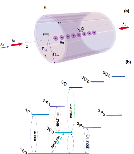
where is the -th Matsubara frequency, is the temperature, is the dipole matrix element of transition with transition frequency , is the classical Green tensor Wylie and Sipe (1984, 1985); Li et al. (2000) for a given waveguide geometry, is the atomic polarizability, the prime on the Matsubara sum indicates that the term is to be taken with half weight, and is the Heaviside step function. We do not present the details of the full theoretical framework used in these calculations as it was previously done by other authors, see Refs. Gorza and Ducloy (2006); Ellingsen et al. (2010) and references therein 111The factor in Eq. (2.3) and the factor in Eq. (2.7) of Ref. Ellingsen et al. (2010) are included through the factor , expressed in Gaussian units, appearing in our expression for the Green tensor, see Eq. (2) below, and accounts for the factor in our Eq. (II). We approximate the geometry of the fiber inner interface by a dielectric capillary of a given thickness , see Fig. 1(a), where and are the inner and outer radii of the capillary and is the radial coordinate of the atom inside the cylinder. We consider the surface in thermal equilibrium with BBR at given temperature . The mean occupation number of photons with energy is given by the Bose-Einstein distribution, . Cold atoms prepared in a given state (either or ) are trapped by the red-detuned standing wave forming the 1D optical lattice inside the fiber, see Fig. 1. The “magic” wavelength of the laser field forming the lattice is chosen in order to cancel the differential ac Stark shift for the clock transition, ( nm Hachisu et al. (2008)). The atomic ensemble temperature can be reduced down to few nK(Hachisu et al., 2008), decreasing the trapping potential depth to , where is the recoil energy. We also assume that the atoms are trapped in the ground vibrational motional state and are located near the lattice nodes, corresponding to the maxima of lattice field intensity, along the axis of a cylinder (), where they are most distant from the dielectric walls.
II.1 Resonant atom-surface interaction
We start our analysis of the - clock transition frequency shift from the first term in Eq. (II), corresponding to virtual dipole absorption and emission of thermal photons. In presence of surface polaritons (Gorza and Ducloy, 2006) or waveguide modes at the atomic transitions frequencies these terms may become resonant Ellingsen et al. (2010). The dashed lines in Fig. 1(b) indicate the virtual transitions contributing to the resonant part of the CP interaction potential. The term arising from virtual emission remains finite even at zero temperature, although it is strongly suppressed due to the small values of the corresponding dipole matrix elements for non-zero nuclear spin isotopes (which vanishes for nuclear spin-zero isotopes). The other contributions come from virtual absorption of thermal photons via the -, -,-, and - pathways. Their amplitudes are suppressed exponentially with decreasing surface temperature.
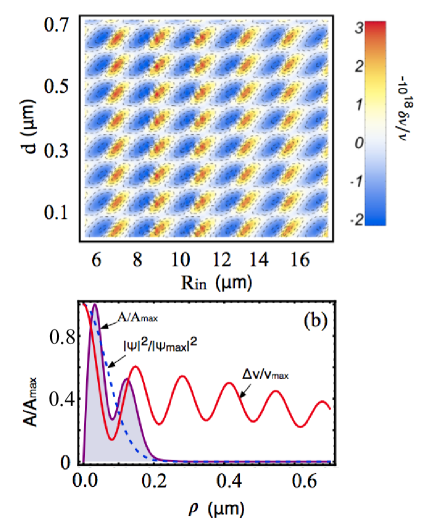
Fig. 2 shows the computed fractional frequency shift of the - clock transition on the capillary axis () caused by the resonant part of the CP interaction potential at the surface temperature K. One can see the resonant structure in its dependence on the capillary thickness parameter and inner radius . The effect ceases (on the capillary axis) as the capillary inner radii grows. For the vacuum-silica-air interface Grass et al. (2016) the cavity effect is small as compared to the case of highly reflective capillary material, Fig. 4. Also, there are no resonances in the relative permitivity corresponding to transitions from or states in divalent atoms. The upper limit on the resonant CP interaction-induced clock transition frequency shift in Hg atoms on the capillary axis (), at surface temperature K and inner core radius is . It can be further reduced by choosing the optimal values of waveguide inner radius and thickness. For atoms the rate of transition -, most contributing to the resonant CP interaction at the room temperature of the surface, is much lower than for . Therefore we do not consider here the resonant CP interaction induced frequency shifts in Sr atom.
The dependence of the resonant CP interaction on the waveguide geometry can be derived from the Green function. The Green function is given by (Li et al., 2000):
| (2) |
where are functions of the frequency and the surface parameters: , , . The resonances of the coefficients at determine the true resonances of the Green function. On the axis () the resonant waveguide mode at the given frequency can be suppressed when minimizing the corresponding sum .
II.2 Nonresonant Casimir-Polder interaction potential
The second term in Eq. (II) corresponds to non-resonant quantum fluctuations of the atomic dipole. Away from resonances and at low surface temperatures this term is the primary contributor to the - transition frequency shift in divalent atoms.
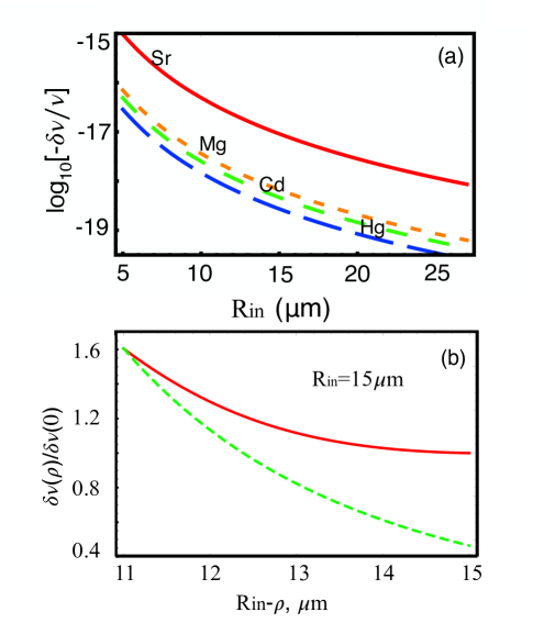
Fig. 4 (a) shows the calculated clock transition frequency shift for the Hg, Cd, Mg and Sr atoms on the silica capillary axis () at surface temperature K. In evaluating the shifts we used the dynamic electric polarizabilities from Refs. Derevianko et al. (2009, 2010); Dzuba (2016). The Hg atom is least sensitive to the nonresonant atom surface interaction due to its relatively low differential static polarizability compared to the other divalent atoms (see Ref. Derevianko et al. (2009) for extensive discussion of this point).
Fig. 4 (b) shows the calculated clock CP-induced transition frequency shift for Hg as a function of distance between the atom and waveguide surface at the fixed value of inner waveguide radius . is the atomic position in cylindrical coordinates with -axis placed at the waveguide axial axis. For a finite-size distribution of atomic motional wavefunction over the radial trapping potential, this dependance will lead to broadening of clock transition line.
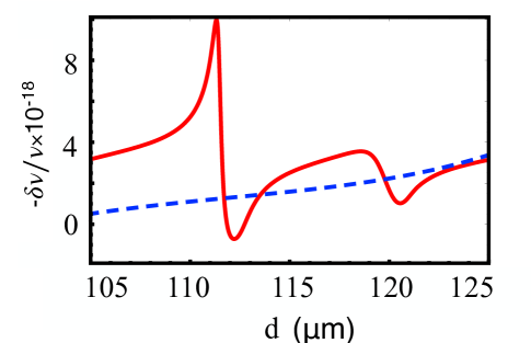
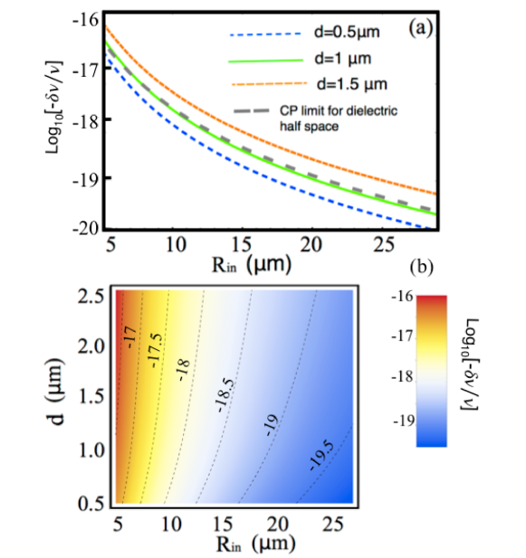
Fig. 5 (a) illustrates the - transition frequency shift as a function of capillary inner radius at different values of the thickness parameter . The gray dashed line shows the CP frequency shift for an atom interacting with the plane dielectric interface at the distance , Casimir and Polder (1948), where is the differential static polarizability of the atomic levels and . As the thickness of the capillary grows, the atoms on the axis are subject to stronger perturbation of their energy levels compared to the case of an atom near the flat dielectric interface. So, for example, at thickness and inner radius the atomic transition frequency shift is about 2.17 times less than the corresponding value for the flat interface: . At the same inner radius value and the thickness the atomic transition frequency shift is about 1.92 times larger than for the flat interface: . As a comparison, in Afanasiev and Minogin (2010) the electrostatic approach was used to determine the van der Waals interaction of the atom with the inner surface of dielectric cylinder () . The interaction potential, as a function of atom distance from the surface, was presented there as , with the factor depending on the distance of the atom from the center of a cylinder. It was found that on the axis of a cylinder the interaction potential felt by the atom is 4 times stronger () than for the atom near the dielectric plane surface at the distance equal to the cylinder radii.
Fig. 5 (b) shows the nonresonant CP interaction induced - clock transition frequency shift in atoms as a function of the capillary inner radius and thickness. One can see the steady frequency shift growth (absolute value) when increasing the capillary thickness and reducing the inner radius of the waveguide.
III Lifetime of trapped atoms and other systematic effects
In this section we further discuss the systematic effects limiting the lifetime of atoms in optical lattice inside the fiber and therefore the stability of fiber clock. We compare different frequency shifts for the atom, which is the main focus of this paper, with the atom, used in the most accurate to this date optical lattice clock Bloom et al. (2014).
One of the detrimental effects comes from the collisions of the atoms with the residual buffer gas molecules. Compared to the macroscopic vacuum chamber, achieving high vacuum in the hollow core fiber is more challenging due to the smallness of inner core. Collisions of cold atoms with the background gas molecules inside the fiber lead to their heating and eventual escape from the optical dipole trap. Considering that the average kinetic energy of the incident buffer gas molecule is much larger than that of the trapped atoms and that the scattering process (inside the shallow optical lattice) happens at relatively large internuclear distances (so that ), one can consider the energy exchange between the two particles using the impulse approximation Johnson (1987). The resulting loss rate is given by , where is the buffer gas number density, and are, respectively, the masses of the buffer gas molecule and trapped atom, is the trapping potential depth, and is the temperature of the buffer gas. The residual buffer gas pressure in the experiments with cold atoms inside the hollow core fiber Okaba et al. (2014); Bajcsy et al. (2011) is . The collisions of cold Hg atoms with molecular nitrogen at buffer gas pressure , temperature K and trapping potential depth K results in a Hg loss rate . This corresponds to the half of the atoms escaping the optical lattice trap after 1 s. In our calculations we used the van der Waals interaction constants given in Margenau (1932). The atom loss limits the interrogation time of the atomic ensemble , and the maximum number of atoms which can be loaded into the optical lattice inside the waveguide. Stronger lattice field intensities can be used during the guiding of the atoms along the fiber. After the atoms are distributed over the fiber length they can be decelerated and further cooled. The intensity of the lattice field can be then reduced. The lower residual gas pressure is required for further improvement of the clock effective operational time and accuracy. After interrogating the atomic ensemble over the time the lost atoms need to be evacuated from the fiber and the loading process to be repeated. The residual buffer gas density inside the fiber can be further reduced using light induced desorption Atutov et al. (2014) together with ultra high vacuum pumping techniques.
The collisional heating of the trapped atoms can be estimated as , where is the most probable speed of the buffer gas molecule, , Johnson (1987) is the differential collision cross section, , is the minimum scattering angle corresponding to the escape of initially trapped atom from the optical lattice, and is the reduced mass. Using the impulse approximation Johnson (1987) one can obtain: . The corresponding heating rate is . At the previously specified buffer gas parameters the calculated collisional heating rate is . To calculate the heating and loss rates for Sr atom we estimated the van der Waals coefficient as , where and are the polarizabilities and ionization potentials of the colliding Sr atom and buffer gas molecule. The ionization energy of molecular nitrogen is . The polarizability Spelsberg and Meyer (1999) a.u. The corresponding Sr loss rate is , . The additional laser field could be used to cool the atoms during the “dark periods” between the subsequent interrogations.
The rate of spontaneous photon scattering from the lattice field ( nm) by Hg atoms trapped in the ground state is given by Miller et al. (1993), where is the Rabi frequency of the - transition, . Considering the large detuning between the frequencies of the lattice field and the resonant frequency of the - transition, such that , the heating due to the spontaneous scattering can be neglected.
Another source of heating comes from the lattice intensity noise Savard et al. (1997). Corresponding heating rate is given by , where is the fractional intensity noise power spectrum, evaluated at the twice the trapping frequency , is the vibrational state of the trapped atom inside the lattice, and is the population of the given vibrational state . Using the polarizability values given in Katori et al. (2015) the lattice intensity noise produced heating rate of atoms in the ground vibrational state can be estimated as: , where is the lattice field intensity. For the lattice potential depth , corresponding heating rate is . As an example, we take the fractional intensity noise power spectrum of an argon ion laser Savard et al. (1997) often used to pump the Ti:sapphire and dye lasers Scott et al. (2001). The resulting heating rate is . For Sr atoms the estimates are: . For the same fractional intensity noise spectrum and the potential depth , one has .
The residual birefringence of the fiber causes the non-uniformity of the polarization along the lattice. This results in additional clock transition frequency uncertainty. The 87Sr clock transition frequency shift due to contribution of the vector and tensor polarizabilities was presented in Westergaard et al. (2011) as , where is the lattice potential depth, is the recoil energy, , are the unitary vectors along the lattice wave vector and the quantization axis, , is the complex polarization vector, and is the degree of the ellipticity of the lattice field. Taking , , where is the difference of the refractive indexes for two orthogonal polarizations and is the length of the atomic cloud inside the fiber, one can estimate the vector polarizability induced frequency shift uncertainty as . For , Okaba et al. (2014), . For cm, , . The vector light-shifts of the components have the opposite signs. Zeeman shift and vector-light shift cancellation techniques have been developed in Takamoto et al. (2006) based on the averaging of frequency measurements for two transitions (). For the same parameters , , , and , , . The dipole polarizabilities of the atom at the magic wavelength are lower than corresponding values for the Sr atom Katori et al. (2015). Therefore the vector and tensor frequency shift are not exceeding those for the atom. Although for bosonic isotopes there are no tensor or vector shifts, the polarization instability along the axis may lead to the multipolar effects induced frequency shifts Taichenachev et al. (2008); Katori et al. (2009), which are however much weaker than the electric-dipole interaction Katori et al. (2015). One could consider using the circularly polarized optical lattice for the atomic clocks with bosonic isotopes.
IV summary
We have studied the feasibility of the optical lattice clock based on the ultra narrow - transition in Hg and other divalent atoms optically trapped inside the micron-scale hollow core waveguide. The effect of the atom-surface interaction on the clock transition frequency inaccuracy at non-zero surface temperature has been evaluated. For an ensemble of cold atoms, with the temperature , optically trapped on the axis of a silica capillary (with surface temperature ), the main contribution to the surface induced - transition frequency shift comes from the nonresonant part of Casimir-Polder interaction potential. This contribution is substantially suppressed for Hg and Cd atoms compared to the other divalent atoms due to their relatively low differential static polarizability. For example, at the inner capillary radius and the capillary thickness , the CP interaction induced - transition frequency shift in atoms is . For the silica capillary waveguide , the calculated upper limits on the - transition frequency shift caused by the resonant atom-waveguide coupling effects are below . In general this shift and the natural linewidth broadening (Purcell effect) can be cotrolled by proper choice of geometric parameters of the waveguide. One could consider the possibility to compensate the nonresonant part of Casimir-Polder interaction on the core axis in combination with its resonant part at certain geometries of the waveguide. Additional effects may appear in case of the resonances in dielectric constants of waveguide material.
We also estimated the atom loss and heating due to the collisions with the buffer gas particles, lattice intensity noise induced heating, spontaneous photon scattering and the residual birefringence induced frequency shifts. To fully realize the potential of the fiber based clock, one needs to solve the problem of the residual buffer gas pressure limiting the interrogation time of the atomic ensemble and the number of atoms which can be loaded into the fiber before they escape the trapping potential.
We would like to thank K. Gibble and H. Katori for motivating discussions. This work was supported in part by the U.S. National Science Foundation grant PHY-1607396.
References
- Treutlein et al. (2004) P. Treutlein, P. Hommelhoff, T. Steinmetz, T. W. Hänsch, and J. Reichel, Phys. Rev. Lett., 92, 203005 (2004).
- Ramírez-Martínez et al. (2011) F. Ramírez-Martínez, C. Lacroûte, P. Rosenbusch, F. Reinhard, C. Deutsch, T. Schneider, and J. Reichel, Advances in Space Research, 47, 247 (2011), ISSN 0273-1177.
- Deutsch et al. (2010) C. Deutsch, F. Ramírez-Martínez, C. Lacroûte, F. Reinhard, T. Schneider, J. N. Fuchs, F. Piéchon, F. Laloë, J. Reichel, and P. Rosenbusch, Phys. Rev. Lett., 105, 020401 (2010).
- Gerritsma et al. (2007) R. Gerritsma, S. Whitlock, T. Fernholz, H. Schlatter, J. A. Luigjes, J.-U. Thiele, J. B. Goedkoop, and R. J. C. Spreeuw, Phys. Rev. A, 76, 033408 (2007).
- Griffith et al. (2010) W. Griffith, S. Knappe, and J. Kitching, Opt. Exp., 18, 27167 (2010).
- Lust and Youngner (2008) L. M. Lust and D. W. Youngner, U.S. Patent 7,359,059 (2008).
- Abbink et al. (2007) H. C. Abbink, E. Kanegsberg, and R. A. Patterson, U.S. Patent 7,239,135 (2007).
- Eklund et al. (2008) E. J. Eklund, A. M. Shkel, S. Knappe, E. Donley, and J. Kitching, Sensors and Actuators A: Physical, 143, 175 (2008), ISSN 0924-4247.
- Wang et al. (2005) Y.-J. Wang, D. Z. Anderson, V. M. Bright, E. A. Cornell, Q. Diot, T. Kishimoto, M. Prentiss, R. A. Saravanan, S. R. Segal, and S. Wu, Phys. Rev. Lett., 94, 090405 (2005).
- Schulz (2009) S. A. Schulz, Scalable Microchip Ion Traps for Quantum Computation, Ph.D. thesis, Univ. Ulm (2009).
- Fröhlich and Yuan (2015) B. Fröhlich and Z. Yuan, Nature Photonics, 9, 781 (2015).
- Cartwright (2013) J. Cartwright, “Quantum cryptography is safe again,” (Aug. 29, 2013), http://www.sciencemag.org/news/2013/08/quantum-cryptography-safe-again.
- Langley (1991) R. Langley, GPS World, 2, 38 (Oct. 1991), available at http://www2.unb.ca/gge/Resources/gpsworld.nov-dec91.corr.pdf.
- Kitching (2007) J. Kitching, GPS World, 18, 52 (Nov. 2007).
- Krawinkel and Schön (2016) T. Krawinkel and S. Schön, GPS World, 27, 50 (Oct. 2016).
- Ely et al. (2014) T. A. Ely, D. Murphy, J. Seubert, J. Bell, and D. Kuang, in 24th AAS/AIAA Space Flight Mechanics Meeting, Spaceflight Mechanics 2014, Advances in the Astronautical Sciences, Vol. 152, edited by R. S. Wilson, R. Zanetti, D. L. Mackison, and O. Abdelkhali, American Astronautical Society (Univelt, San Diego, 2014) p. 51, available at https://www.researchgate.net/publication/260036335_Expected_Performance_of_the_Deep_Space_Atomic_Clock_Mission.
- Knappe (2008) S. Knappe, in Comprehensive Microsystems, Vol. 3, edited by Y. B. Gianchandani, O. Tabata, and H. Zappe (Elsevier, Amsterdam, 2008) pp. 571–612.
- Kishimoto et al. (2006) T. Kishimoto, H. Hachisu, J. Fujiki, K. Nagato, M. Yasuda, and H. Katori, Phys. Rev. Lett., 96, 123001 (2006).
- Fortagh et al. (1998) J. Fortagh, A. Grossmann, C. Zimmermann, and T. W. Hänsch, Phys. Rev. Lett., 81, 5310 (1998).
- Cregan et al. (1999) R. F. Cregan, B. J. Mangan, J. C. Knight, T. A. Birks, P. S. J. Russell, P. J. Roberts, and D. C. Allan, Science, 285, 1537 (1999).
- Okaba et al. (2014) S. Okaba, T. Takano, F. Benabid, T. Bradley, L. Vincetti, Z. Maizelis, V. Yampol’skii, F. Nori, and H. Katori, Nature Comm., 5, 4096 (2014).
- Katori (2002) H. Katori, in Proc. 6th Symposium Frequency Standards and Metrology, edited by P. Gill (World Scientific, Singapore, 2002) p. 323.
- Bloom et al. (2014) B. J. Bloom, T. L. Nicholson, J. R. Williams, S. L. Campbell, M. Bishof, X. Zhang, W. Zhang, S. L. Bromley, and J. Ye, Nature, 506, 71 (2014).
- Derevianko and Pospelov (2014) A. Derevianko and M. Pospelov, Nature Physics, 10 (2014).
- Wcisło et al. (2016) P. Wcisło, P. Morzyński, M. Bober, A. Cygan, D. Lisak, R. Ciuryło, and M. Zawada, Nature Astronomy, 1, 0009 (2016).
- Gross and Haroche (1982) M. Gross and S. Haroche, Phys. Rep., 93, 301 (1982).
- Meiser et al. (2009) D. Meiser, J. Ye, D. R. Carlson, and M. J. Holland, Phys. Rev. Lett., 102, 163601 (2009).
- Yu and Chen (2007) D. Yu and J. Chen, Phys. Rev. Lett., 98, 050801 (2007).
- Hachisu et al. (2008) H. Hachisu, K. Miyagishi, S. G. Porsev, A. Derevianko, V. D. Ovsiannikov, V. G. Pal’chikov, M. Takamoto, and H. Katori, Phys. Rev. Lett., 100, 053001 (2008).
- Petersen et al. (2008) M. Petersen, R. Chicireanu, S. T. Dawkins, D. V. Magalhães, C. Mandache, Y. Le Coq, A. Clairon, and S. Bize, Phys. Rev. Lett., 101, 183004 (2008).
- McFerran et al. (2012) J. J. McFerran, S. Mejri, L. Yi, S. D. Manno, W. Zhang, J. Guena, Y. Le Coq, and S. Bize, Phys. Rev. Lett., 108, 183004 (2012).
- Takamoto et al. (2015) M. Takamoto, I. Ushijima, M. Das, N. Nemitz, T. Ohkubo, K. Yamanaka, N. Ohmae, T. Takano, T. Akatsuka, A. Yamaguchi, and H. Katori, C. R. Physique, 16, 489 (2015).
- Tyumenev et al. (2016) R. Tyumenev, M. Favier, S. Bilicki, E. Bookjans, R. Le Targat, J. Lodewyck, D. Nicolodi, Y. Le Coq, M. Abgrall, J. Guéna, L. De Sarlo, and S. Bize, New J. Phys., 18, 113002 (2016).
- Porsev and Derevianko (2006) S. G. Porsev and A. Derevianko, Phys. Rev. A, 74, 020502 (2006).
- Fevrier et al. (2009) S. Fevrier, F. Gerome, A. Labruyere, B. Beaudou, J. Humbet, and J.-L. Auguste, Opt. Lett., 34, 2888 (2009).
- Gebert et al. (2014) F. Gebert, M. H. Frosz, T. Weiss, Y. Wan, A. Ermolov, N. Y. Joly, P. O. Schmidt, and P. St. J. Russell, Opt. Exp., 22, 15388 (2014).
- Derevianko et al. (2009) A. Derevianko, B. Obreshkov, and V. A. Dzuba, Phys. Rev. Lett., 103, 133201 (2009).
- Ellingsen et al. (2010) S. Ellingsen, S. Y. Buhmann, and S. Scheel, Phys. Rev. A, 82, 032516 (2010).
- Jhe et al. (1987) W. Jhe, A. Anderson, E. A. Hinds, D. Meschede, L. Moi, and S. Haroche, Phys. Rev. Lett., 58, 666 (1987).
- Gorza and Ducloy (2006) M. Gorza and M. Ducloy, Eur. Phys. J.D, 40, 343 (2006).
- Wylie and Sipe (1984) J. M. Wylie and J. E. Sipe, Phys.Rev.A, 30, 1185 (1984).
- Wylie and Sipe (1985) J. M. Wylie and J. E. Sipe, Phys.Rev.A, 32, 2030 (1985).
- Li et al. (2000) L. W. Li, M.-S. Leong, T.-S. Yeo, and P.-S. Kooi, J. of Electromagnetic waves and applications, 14, 961 (2000).
- Note (1) The factor in Eq. (2.3) and the factor in Eq. (2.7) of Ref. Ellingsen et al. (2010) are included through the factor , expressed in Gaussian units, appearing in our expression for the Green tensor, see Eq. (2) below, and accounts for the factor in our Eq. (II).
- Grass et al. (2016) D. Grass, J. Fesel, S. G. Hofer, N. Kiesel, and M. Aspelmeyer, Appl. Phys. Lett., 108, 221103 (2016).
- Derevianko et al. (2010) A. Derevianko, S. Porsev, and J. Babb, At. Data Nucl. Data Tables, 96, 323 (2010).
- Dzuba (2016) V. A. Dzuba, (2016), private communication.
- Casimir and Polder (1948) H. B. G. Casimir and D. Polder, Phys. Rev., 73, 360 (1948).
- Afanasiev and Minogin (2010) A. Afanasiev and V. Minogin, Phys.Rev. A, 82, 052903 (2010).
- Johnson (1987) R. E. Johnson, Atomic and Molecular Collisions, Vol. 2 (Academic Press Inc., New York, 1987).
- Bajcsy et al. (2011) M. Bajcsy, S. Hofferberth, T. Peyronel, V. Balic, Q. Liang, A. S. Zibrov, V. Vuletic, and M. D. Lukin, Phys. Rev. A, 83, 063830 (2011).
- Margenau (1932) H. Margenau, Phys. Rev., 40, 387 (1932).
- Atutov et al. (2014) S. Atutov, N. Danilina, S. L. Mikerin, and A. Plekhanov, Optics Comm., 315, 362 (2014).
- Spelsberg and Meyer (1999) D. Spelsberg and W. Meyer, J. Chem. Phys., 111, 9618 (1999).
- Miller et al. (1993) J. D. Miller, R. A. Cline, and D. J. Heinzen, Phys. Rev. A, 47, R4567 (1993).
- Savard et al. (1997) T. A. Savard, K. M. O’Hara, and J. E. Thomas, Phys. Rev. A, 56, R1095 (1997).
- Katori et al. (2015) H. Katori, V. D. Ovsiannikov, S. I. Marmo, and V. G. Palchikov, Phys. Rev. A, 91, 052503 (2015).
- Scott et al. (2001) R. P. Scott, C. Langrock, and B. H. Kolner, IEEE Journal on Selected Topics in Quantum Electronics, 7, 641 (2001).
- Westergaard et al. (2011) P. G. Westergaard, J. Lodewyck, L. Lorini, A. Lecallier, E. A. Burt, M. Zawada, J. Millo, and P. Lemonde, Phys. Rev. Lett., 106, 210801 (2011).
- Takamoto et al. (2006) M. Takamoto, F.-L. Hong, R. Higashi, Y. Fujii, M. Imae, and H. Katori, J. Phys. Soc. Jpn., 75, 104302 (2006), http://dx.doi.org/10.1143/JPSJ.75.104302 .
- Taichenachev et al. (2008) A. V. Taichenachev, V. I. Yudin, V. D. Ovsiannikov, V. G. Pal’chikov, and C. W. Oates, Phys. Rev. Lett., 101, 193601 (2008).
- Katori et al. (2009) H. Katori, K. Hashiguchi, E. Y. Il’inova, and V. D. Ovsiannikov, Phys. Rev. Lett, 103, 153004 (2009).