The geometry of a radio pulsar beam
Abstract
Taxonomy of radio pulsar profiles is mostly based on a system of Ptolemaic artificiality, consisting of separated rings and a core, arbitrarily located at disparate altitudes in the magnetosphere. Diversity of observed profile shapes clearly exceeds the interpretive capability of such conal model. Moreover, bifurcated features observed in pulsar profiles imply a system of fan beams radially extending away from the dipole axis. The bifurcations can be understood as the imprint of the elementary radiation pattern of the long-sought radio emission mechanism, thus identifying the latter. Their size, however, is several times larger than implied by the curvature of magnetic dipole lines. Here I show that the illusion of disconnected rings and the size of bifurcated features can be explained through a natural geometry which combines the properties of both the cone and the fan beam. It is a flaring spiral which makes several revolutions around the dipole axis on its way to leave the magnetosphere. Such geometry is consistent with a stream of outflowing and laterally drifting plasma. The bifurcated components are so wide, because the curvature on such a spiral is larger than that of the dipolar magnetic field, hence they are consistent with the extraordinary mode curvature radiation.
keywords:
pulsars: general – pulsars: individual: PSR B154109 – pulsars: individual: PSR B182105 – pulsars: individual: PSR B194635 – pulsars: individual: PSR J10125307 – radiation mechanisms: non-thermal.1 Introduction
Since the discovery of pulsars in 1967 (Hewish et al. 1968) thousands of pulse profiles have been observed at different radio frequencies (Hankins & Rankin 2010, hereafter HR10; Mitra et al. 2015, hereafter MAR15; Dai et al. 2015). Some of the profiles are approximately symmetric, which has led to the nested cone model of the radio emission beam (Ruderman & Sutherland 1975; Backer 1976; Rankin 1983) – the main model in use so far. The corresponding emission region consists of two rings and a low-altitude filled-in core region, all centered at the dipole axis and localised at well separated altitudes in pulsar magnetosphere (Rankin 1990, 1993; Gangadhara and Gupta 2001; although compare Wright 2003). The model suffers from multiple problems: the selection of up to three altitudes lacks physical justification and offers limited understanding of the large diversity of profile shapes. The profiles are often highly asymmetric and have components with flux ratio which curiously evolves with frequency. The latter effect has led to the idea of general patchiness of the beam (Lyne & Manchester 1988; Karastergiou & Johnston 2007). The flux ratio reversal in components observed at different is a ubiquitous phenomenon, observed even for profiles that look highly symmetric at some (e.g. PSR B052521, B030119, B113316, HR10, MAR15). In other profiles the change of flux ratio with has extreme magnitude, with components disappearing at some pulse longitudes, and appearing at others (e.g. PSR B154109, B173713, B182105, HR10). Moreover, precursor and postcursor components appear on either side of many profiles as additional features. Some of them, but also the usual “conal” components (e.g. B193316, Mitra et al. 2016; B194635, Mitra & Rankin 2017) belong to the class of bifurcated features (split emission components and double notches). These are often observed far from the main pulse, and may have highly symmetric, double form that has been attributed directly to the elementary radiation pattern of the curvature radiation (PSR J10125307, Dyks et al. 2010, hereafter DRD10; J04374715, Navarro et al. 1997; Osłowski et al. 2014).
2 The new emission geometry
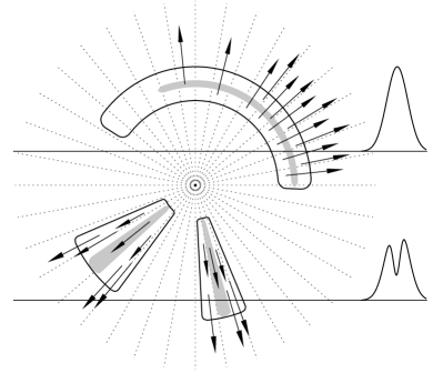
As explained in Fig. 1, the nested cone model is helpless with the bifurcated components (BCs), since the flaring shape of dipolar magnetic field lines implies the outflow of the radio emitting plasma away from the dipole axis. To produce the central dip in a BC, the charges would have to stop emitting for a short while, and right at the moment when they are crossing the middle of the emission region. To explain the BCs, the fan beam geometry has therefore been rediscovered (DRD10), after years of neglect since 1987, when it was first suggested (Michel 1987). In the fan beam model, the beam extends along the trajectory of plasma motion (Fig. 1) so the presumed radial motion of plasma does not smear out the bifurcation.
However, there exists a geometry which is natural from the point of view of physics, and combines the geometric properties of a cone and a fan beam. It is a flaring spiral (or flaring helix) which makes several revolutions around the dipole axis while the plasma is streaming along this helix towards the light cylinder. When the observer’s sightline is traversing through coils of such a spiral, pairs of altitudes are detected, which decrease towards the profile center. This creates the misleading illusion of nested cones, which has been the rule in taxonomical identification of profiles for decades.
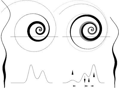
Assuming that radio emission observed at different frequencies is on average generated at different altitudes (or radial distances ), different segments of the spiral, located further from, or closer to its origin are radio bright (detectable). With the change of , the brightest part of emission region is then rotated in the magnetic azimuth, as measured around the dipole axis. The brightest part of the ensuing beam is shown in Fig. 2 as the increased thickness of the spiral which is viewed face on. As can be seen in the figure, the nontrivial evolution of the components’ flux ratio with is an inherent feature of the flaring spiral beam. Similarly, the disappearance of components, and their appearance at a new pulse longitude occurs easily. Thus, the prime result of the -dependent emission altitude is the -dependent components’ flux ratio.
The profiles are also well known of widening at low frequencies (Mitra & Rankin 2002), i.e. the peak-to-peak separation between components increases. This implies that at higher the sky-projected spiral must be coiled more tightly, i.e. more energetic electrons must follow a helix that is anchored or revolving closer to the dipole axis. The radio waves, emitted mostly tangentially to the helical trajectory, are emitted at the opening angle , where and are the azimuthal and tangent-to- velocity components. I attribute the spiral geometry to the drift within the radio emission region, where and , are the electric field components parallel and orthogonal to the local . When only the magnitude of is fluctuating or nonuniform, and are positively correlated. The strong induces both the large Lorentz factor (hence high ) and the large which enables the electrons to make the inner coils at lower altitudes, where the flux tube (and the resulting spiral) is narrower. As verified numerically, for a larger (keeping total ), the coils are produced at smaller and the spiral is contracted.111This is not inconsistent with the formula , since the latter is valid for a fixed . The spread of then provides a natural single cause for the association of high , low and small . However, when the direction of is fluctuating (instead of the magnitude), then and (hence and ) are anticorrelated and the high emission may form a wider spiral at larger . With the unscreened within the radio emission region, the continuing acceleration increases the electrons’ energy with , as long as the coherent radiative losses are smaller than the energy gain. This also implies the increase of emitted with . Note that the larger average altitude of the high- emission can be consistent with smaller aberration-retardation (AR) effects when is larger and the detectable spiral coils are produced at smaller (cf. the grey and black spirals in Fig. 2).
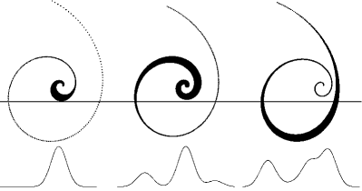
Taking the above-described effects together, it becomes possible to interpret instances of profile evolution which have been unaccessible for the nested cone model. Fig. 3 presents the interpretation of profile evolution for B154109 (cf. Fig. 8 in HR10). The core component at MHz becomes surrounded by two asymmetric peripheric components (PCs) at MHz. Above 1.4 GHz the leading PC approaches the core and they merge with a bridge of emission in between. Fig. 4 presents a different viewing geometry for B182105 (cf. Fig. 9 in HR10). This time it is the trailing PC that merges with the core at high , because of the narrowing of the spiral and the AR-related distortions.

3 Bifurcated components and the mechanism of radio emission
The bifurcated emission components (BCs), when not blurred or overlaid on other components, have highly symmetric shape, which is very close to the elementary radiation pattern of curvature radiation (CR) propagating in the extraordinary polarisation mode (DRD10; Gil et al. 2004). Moreover, the peaks of the BCs approach each other with increasing , at the rate consistent with the CR mechanism (Dyks & Rudak 2012). However, the observed scale of wide BCs ( between and ) was an order of magnitude larger than the opening angle of the CR beam in dipolar magnetosphere: , where cm is the curvature radius of the emitting electrons’ trajectory, is a viewing angle factor of the order of a few, and is the observation frequency in GHz. Since is fixed by the choice of the telescope’s receiver, for the observed could be explained by the curvature radii of cm, i.e. about two orders of magnitude smaller than radii of dipolar field lines along which the emitting plasma was assumed to move. This problem is solved by the flaring helix, since the radius of curvature in the helix can be much smaller than that of the -field lines, which only provide the outer envelope for the helix (see the side views of flaring helices in Fig. 2). This same effect simultaneously explains why the widest BCs are observed at longitudes far away from the main pulse: the radio waves are emitted at the angle which can be larger than the opening angle of the polar tube envelope. For a standard (cylindrical) helix with very elongated coils (, where is the transverse circulation radius and – the upward advance of the helix after one coil) the radius of curvature is . The large implies both smaller curvature radii and more slanted emission direction, which is in line with the peripheric occurence of BCs (as precursors or PCs). With the smaller offered by the helix, the extraordinary mode CR provides an ideal origin for the astonishing symmetry and the -dependent merging of BCs. The formula for could in principle be used to estimate the curvature radius in detectable parts of the helix. However, the resulting formula: depends in a high power on the unknown which can be anywhere between and (and likely larger than since it is roughly an inversed product of two sine functions).
4 Discussion
The exact shape of the flaring helix, which represents the average radio emission region, depends on the unknown distribution of with altitude. The entire helix may be fixed in azimuth at some surface irregularity of -field or move azimuthally in such a way that some orientation is preferred whenever it is crossed by the line of sight. Single pulse phenomena such as different drift modes may suggest time variability of the entire helix. The radio-bright part of the helix does not seem to extend for many azimuthal turns, because profiles with numerous components (of M and Q type) are rarely observed. The M and Q profiles tend to contain several approximately equidistant components which suggests that tangents to the flaring helix may sometimes form a roughly Archimedean spiral on the sky. Performed calculations reveal that large portion of parameter space results in Archimedean-like spirals, e.g. they appear when , , and is in the large range between and . The calculations also suggest that the helix is anchored near the dipole axis, not at the polar cap rim, as one may expect if the spacious polar regions of millisecond pulsars are to be filled in with emission. At some altitude the sky-projected spiral readily unwinds into a real fan beam, either because of the flaring of the dipolar field lines, or because of the value of . The outcome is then similar to the mapped beam of PSR J19060746 (Desvignes et al. 2013).
The flaring spiral beam solves the problem of disconnected emission rings, explains the “approximately conal” symmetry of profiles, allows for the peculiar -evolution of profiles, and for the existence of wide bifurcated components. The spiral beam opens new possibilities to interpret the shapes of average pulsar profiles and of the single pulse phenomena (such as drifting, nulling or profile moding).
acknowledgements
I thank B. Rudak and A. Frankowski for discussions and comments on the manuscript. This work was funded by the National Science Centre grant DEC-2011/02/A/ST9/00256.
References
- Backer (1976) Backer D. C., 1976, ApJ, 209, 895
- Dai et al. (2015) Dai S., Hobbs G., Manchester R. N., Kerr M., Shannon R. M., van Straten W., Mata A., Bailes M., Bhat N. D. R., et al., 2015, MNRAS, 449, 3223
- Desvignes et al. (2013) Desvignes G., Kramer M., Cognard I., Kasian L., van Leeuwen J., Stairs I., Theureau G., 2013, in van Leeuwen J., ed., IAU Symposium Vol. 291 of IAU Symposium, PSR J1906+0746: From relativistic spin-precession to beam modeling. pp 199–202
- Dyks & Rudak (2012) Dyks J., Rudak B., 2012, MNRAS, 420, 3403
- Dyks et al. (2010) Dyks J., Rudak B., Demorest P., 2010, MNRAS, 401, 1781 (DRD10)
- Gangadhara & Gupta (2001) Gangadhara R. T., Gupta Y., 2001, ApJ, 555, 31
- Gil et al. (2004) Gil J., Lyubarsky Y., Melikidze G. I., 2004, ApJ, 600, 872
- Hankins & Rankin (2010) Hankins T. H., Rankin J. M., 2010, AJ, 139, 168 (HR10)
- Hewish et al. (1968) Hewish A., Bell S. J., Pilkington J. D. H., Scott P. F., Collins R. A., 1968, Nat, 217, 709
- Karastergiou & Johnston (2007) Karastergiou A., Johnston S., 2007, MNRAS, 380, 1678
- Lyne & Manchester (1988) Lyne A. G., Manchester R. N., 1988, MNRAS, 234, 477
- Michel (1987) Michel F. C., 1987, ApJ, 322, 822
- Mitra et al. (2015) Mitra D., Arjunwadkar M., Rankin J. M., 2015, ApJ, 806, 236 (MAR15)
- Mitra & Rankin (2017) Mitra D., Rankin J., 2017, ArXiv e-prints
- Mitra et al. (2016) Mitra D., Rankin J., Arjunwadkar M., 2016, MNRAS, 460, 3063
- Mitra & Rankin (2002) Mitra D., Rankin J. M., 2002, ApJ, 577, 322
- Navarro et al. (1997) Navarro J., Manchester R. N., Sandhu J. S., Kulkarni S. R., Bailes M., 1997, ApJ, 486, 1019
- Osłowski et al. (2014) Osłowski S., van Straten W., Bailes M., Jameson A., Hobbs G., 2014, MNRAS, 441, 3148
- Rankin (1983) Rankin J. M., 1983, ApJ, 274, 333
- Rankin (1990) Rankin J. M., 1990, ApJ, 352, 247
- Rankin (1993) Rankin J. M., 1993, ApJ, 405, 285
- Ruderman & Sutherland (1975) Ruderman M. A., Sutherland P. G., 1975, ApJ, 196, 51
- Wright (2003) Wright G. A. E., 2003, MNRAS, 344, 1041