Elastic wake instabilities in a creeping flow between two obstacles
Abstract
It is shown that a channel flow of a dilute polymer solution between two widely spaced cylinders hindering the flow is an important paradigm of an unbounded flow in the case in which the channel wall is located sufficiently far from the cylinders. The quantitative characterization of instabilities in a creeping viscoelastic channel flow between two widely spaced cylinders reveals two elastically driven transitions, which are associated with the breaking of time-reversal and mirror symmetries: Hopf and forward bifurcations described by two order parameters and , respectively. We suggest that a decrease of the normalized distance between the obstacles leads to a collapse of the two bifurcations into a codimension-2 point, a situation general for many non-equilibrium systems. However, the striking and unexpected result is the discovery of a mechanism of the vorticity growth via an increase of a vortex length at the preserved streamline curvature in a viscoelastic flow, which is in sharp contrast to the well-known suppression of the vorticity in a Newtonian flow by polymer additives.
The addition of a small amount of high-molecular-weight flexible polymer molecules into a fluid strongly affects a flow in a wide range of spatial and temporal scales. Polymers being stretched by a velocity gradient particularly in a flow with curvilinear streamlines generate elastic (hoop) stresses, which react back on the flow and modify it via elastic instabilities and at further stretching lead to elastic turbulence (ET) discovered at groisman ; myreview . Elastic turbulence is a chaotic flow characterized by a strong enhancement of a flow resistance, a power-law decay of velocity power spectra with an exponent , and orders of magnitude enhancement of mixing compared with diffusion groisman1 ; groisman2 ; myreview . Theory lebedev and numerical simulations berti ; berti1 ; yatou ; khomami ; grilli of ET consider unbounded, homogeneous, and isotropic flow of a dilute solution of polymers with linear elasticity that is strongly distinguished from bounded, anisotropic, and inhomogeneous flow studied experimentally groisman1 ; groisman2 ; teo1 ; teo2 ; jun ; liu ; jun2 . There are two approaches to resolve the evident discrepancy: either to look for flow geometry, where unbounded, homogeneous, and isotropic flow of ET can be realized experimentally, or to develop ET theory for a bounded container with a nonzero mean velocity .
In our search for the experimental realization of an unbounded, homogeneous, and isotropic flow of a viscous polymer solution at , we consider a flow past an obstacle or array of obstacles. In spite of the fact that the flow past the obstacle is considered as a paradigmatic problem of fluid mechanics for both Newtonian and viscoelastic fluids widely investigated in the past both experimentally and numerically and is highly relevant to many industrial applications, the studies of highly elastic fluids at in such a flow geometry are rather limited.
In a viscoelastic creeping flow past a cylinder, three nondimensional parameters control the dynamical behavior of the flow, namely, the Weissenberg number and two geometrical parameters: the blockage ratio of the cylinder diameter to the channel width , , and the confinement ratio of the channel height to width, . Here is the ratio of the nonlinear elastic stress to its dissipation via relaxation and defines a degree of polymer stretching, is the average flow velocity, and is the longest polymer relaxation time bird . The parameter controls the relative strength of shear near the wall and extension near a stagnation region, whereas controls the two-dimensional (2D) versus 3D effects. For both small and one expects mainly 2D confined flow near an unbounded cylinder with large extensional strains.
At , two approaches have been explored in experiments as well as simulations: to study a friction coefficient either of a free-falling body (cylinder or sphere) at a terminal velocity or of a channel flow past a cylinder or an array of cylinders. In the former case, a substantial number of experimental studies with various polymer solutions have been conducted and controversial results even on have been obtained james . Reliable experimental data on are reported in Ref. muller ; however, the quantitative discrepancy between its value and numerical simulations remains unresolved khomami1 .
At moderate , a detailed investigation of a viscoelastic creeping flow past a cylinder reveals a stationary elastic wake instability, which leads to the formation of a 3D regularly spaced cellular structure McKinley . A further increase in results in a subsequent transition to a time-dependent flow McKinley . Subsequent experiments in a microchannel flow past a strongly confined cylinder with various and and in a wide range of and were conducted in Ref. kenney . In this work, a downstream elastic instability is observed only at and , which is not the creeping flow discussed here. Moreover, an upstream instability at higher and was also reported kenney .
More extensive studies of a purely elastic instability were conducted both experimentally and numerically in a creeping flow in a wall-bounded channel with a periodic array of cylinders. For closely spaced cylinders, a pair of vortices between cylinders was observed for both Newtonian and viscoelastic fluids at below an instability at khomami2 ; khomami3 . Above , a sharp increase in related to the onset of noisy oscillations of a cross-stream velocity due to breaking of time-reversal symmetry was found. The coupling between the hoop stress arising from curved streamlines and the velocity perturbations plays a key role in triggering the instability khomami3 . It resembles an oscillatory instability in an extensional viscoelastic flow realized in T-junction geometry with a long recirculating cavity atul . Two-dimensional numerical simulations of the viscoelastic flow for closely spaced cylinders reveal an instability associated with the cross-stream velocity fluctuations at resulting from a time-dependent instability of the vortex pairs, generated at , in agreement with the experiments ellero . Moreover, both the growth of and root-mean-square (rms) fluctuations of the cross-stream velocity with at reveals a square-root dependence on characterized as the forward bifurcation cross . Three-dimensional simulations in grilli reproduce the growth with at , the same as in a 2D flow, pointing out the 2D nature of perturbations causing the instability.
In this Letter we present experimental results of a viscoelastic creeping channel flow instability between two widely-spaced cylinders, which provide a quantitative answer to the following questions. How is a velocity field modified by elasticity in an unbounded () flow between two cylinders and what is the corresponding order parameter of the elastic instability? How do polymers alter the flow resistance as a result of the instability? What are the flow velocity field and its spectral properties and what is the flow structure between the cylinders?
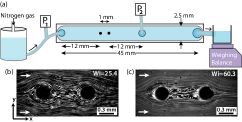
A dilute polymer solution of high-molecular-weight polyacrylamide (molecular weight MDa, Polysciences) at a concentration ppm (, where ppm for the polymer used liu2 is the overlap concentration) is prepared in a viscous solvent of sucrose and NaCl by weight. The solvent viscosity at is measured to be in a commercial rheometer (AR-1000; TA instruments). The addition of the polymer to the solvent increases the solution viscosity up to . The stress-relaxation method liu2 is employed to obtain s. The fluid is driven by nitrogen gas at a pressure up to psi and is injected via the inlet into a linear channel of dimension , shown schematically in Fig. 1(a). The fluid flow is hindered by the two widely-spaced cylindrical obstacles of made of stainless steel separated by a distance of and embedded at the center of the channel. Thus the geometrical parameters of the channel are and and the normalized distance between the cylinders .
Two piezoresistive pressure sensors (ABP series, Honeywell) measure the fluid pressure at two locations: before the channel inlet and after the obstacles, marked with and , respectively, in Fig. 1(a). The fluid exiting the channel outlet is weighed instantaneously as a function of time by a PC-interfaced balance (BA210S, Sartorius) with a sampling rate of and a resolution of . The time-averaged fluid discharge rate is estimated as . For flow visualization, the solution is seeded with fluorescent particles of diameter (Fluoro-Max green fluorescent, Thermo Scientific). The region between the obstacles is imaged in the mid-plane directly via a microscope (Olympus IX70), illuminated uniformly with a light-emitting diode (Luxeon Rebel) at wavelength, and a CCD camera (GX1920; Prosilica) attached to the microscope records about 5000 images of resolution pixels at a rate of . We use particle image velocimetry (PIV) to obtain the spatially resolved velocity in the region between the cylinders piv . An interrogation window of () with overlap is chosen to procure .
Figures 1(b) and 1(c) display two streak flow images at two . At lower , the flow between the obstacles is close to a potential one and similar to the potential flow of a Newtonian fluid at , whereas at the streaks of the inner flow velocity are much shorter than those of an outside flow and vortices are clearly identified (see also movies 1 and 3 in Ref. sm ). These images qualitatively illustrate the difference of the flow field between the obstacles below and above the instability onset.
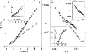
A quantitative characterization of the elastic wake instability through the dependence of the pressure drop in the channel on the average flow speed is presented in Fig. 2(a). The transition is identified by the deviation of from a linear dependence of on characteristic of a potential flow past obstacles in a Newtonian solvent and the polymer solution at low , as shown in Fig. 2(a) together with the linear fit. Moreover, the rms normalized pressure fluctuations grow with for polymer solution above the transition, as shown in the inset in Fig. 2(a), whereas for the Newtonian solvent remains constant. Here, and the pressure drop along the small pipe connected to the inlet of the channel is estimated moody from , where is the Reynolds number for the pipe flow, the fluid density , and mm and mm are the radius and length of the pipe, respectively. To highlight more clearly the transition region, the data are shown in Fig. 2(b) on a high-resolution plot via the dependence of the friction factor on the Reynolds number , where the hydraulic radius is mm and mm is the distance between the inlet and the location of pressure measurement in the channel (marked in Fig. 1(a)). In the main plot the data for the Newtonian solvent in the whole range of are described by the fit with a large scatter before the elastic instability. In the top inset in Fig. 2(b), the same data are plotted as versus and the transition at is identified as well so the scatter in the vicinity and before is rather large.
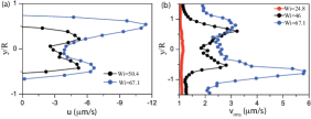
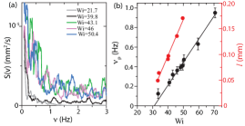
Figure 1SM in Ref. sm illustrates the time-averaged streamwise velocity profile obtained in the horizontal midplane by PIV as a function of for several locations in the region between the obstacles at four below and above the transition. Here x and y are longitudinal and transverse coordinates of the channel, respectively, with ()=() located at the center of the upstream cylinder. At , the flow is in the forward direction everywhere between the obstacles, while at a reverse flow is developed that is demonstrated in the insets by negative values of u between the obstacles (see Fig. 1SM in Ref. sm ). A further magnified negative velocity profile is presented in Fig. 3(a) at for two , where strong velocity gradients are developed that lead to a significant polymer stretching. It is reminiscent of sharp radial velocity gradients observed in the core of a solitary vortex pair resulting from a pure elastic instability in a viscoelastic Couette flow groisman3 .
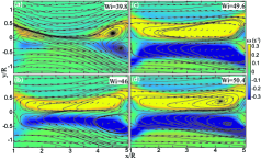
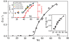
To analyze further the velocity field , we compute time-averaged vorticity as . Figure 4 shows the vorticity map between the obstacles for . A small vortex pair appears first at (see movie 2 in Ref. sm ) in the vicinity of the downstream cylinder and expands in size with , as shown in Fig. 4. The quantitative dependence of the spatially averaged, either positive or negative, vorticity on is presented in Fig. 5 together with the fit based on the Landau equation for the order parameter of the continuous transition cross , which yields as the fit parameter. A similar fit is used to characterize the transition in the dependence of on , as shown in the bottom inset in Fig. 2(b), where a close value of but with significantly larger scatter is obtained. Here is the pressure drop for a potential flow (see Fig. 2(a)). The top inset in Fig. 5 shows the dependences of an absolute value of the reverse streamwise flow velocity at and the rms cross-stream velocity fluctuations at four locations close to the downstream cylinder on that are time averaged for about s. A similar fit by the Landau equation used for provides , in accord with the value obtained for , since the vorticity and the reverse flow velocity between the obstacles are directly related to each other. On the other hand, a fit to the data versus by provides significantly lower than the values obtained above. It should be emphasized that the values above the transition are an order of magnitude smaller than , which should correspond to their contributions to the friction factor . Indeed, as one can see from the bottom inset in Fig. 2(b), the whole range of change of is about 0.5. Then a value, about 10 times smaller, corresponding to the ratio is inside the scatter and cannot be identified in . Though from the dependence of versus in the bottom inset in Fig. 5 the early transition is clearly characterized by the fit with , close to the above value.
To further understand the nature of the instability associated with , we compute the frequency power spectra of the cross-stream velocity v for five , as shown on a linear scale in Fig. 6(a). The peaks in are distinctly evident at with a characteristic frequency varying linearly with and approaching zero at (see Fig. 6(b)), whereas at is rather smooth. Thus, the first transition at , taken as the average of values obtained from and , is indicative of the Hopf bifurcation cross ; atul . From profiles of at for three one finds that at the velocity fluctuations are much higher than an instrumental noise level and two peaks in the profiles indicate the border between the outer and inner velocity flow regions (see Fig. 3(b)). According to the peak locations the inner region widens with . Similar growth of characterizes an elastic instability observed in 2D numerical simulations of a viscoelastic channel flow past a periodic array of closely spaced () cylinders, where the velocity power spectra and the scaling at are presented in Figs. 9 and 10 of Ref. ellero and in experiments khomami2 ; khomami3 . The second steady forward bifurcation is not observed in this case probably due to the difference in versus 3.3 used in our experiment. Thus, in the current experiment two subsequent transitions, close in values, are found: first at as the Hopf bifurcation and second at as the forward bifurcation. In the latter case, is taken as the average of values obtained from and . The value of found from the dependence of on is higher with much larger scatter and a lower resolution in the detection, as pointed out above.
What is the physics behind the both elastic instabilities described above? A small vortex pair appearing due to a breaking of mirror symmetry generates the hoop stress due to a curvature, which interacts with the cross-stream velocity perturbations. The latter arises due to the breaking of time-translational invariance. As a result, the Hopf bifurcation appears first at and is similar to that found by us in T-junction geometry with a long recirculating cavity atul . A further increase in the external driving leads via the second instability to an enhancement of the vortex vorticity and so the elastic stress . Indeed, if the vortex preserves its curvature, the hoop stress grows bird as , where is the vortex radius. Then, above the second transition one gets , which finally would cause the vortex collapse due to the growing hoop stress. So this means that the vortex pair would be suppressed. Indeed, for example, an inhibition of a von Kármán vortex street in a cylinder wake in a Newtonian fluid by an injection of a polymer additive is observed cadot ; goldburg . The way out from this evident discrepancy is a growing vortex size with . If for simplicity we introduce a vortex length , then the same estimate leads to . As found from the experiment, at (see Fig. 6(b)) and so remains intact and thus the vortex remains stable. The question arises why the second transition was not observed in the previous experiments of a flow past a periodic array of cylinders. The main reason is the difference in the value of that is larger in the current experiment. So if decreases, both transitions finally may collapse, leading to a codimension-2 point steinberg ; groisman4 ; cross , where two order parameters reach zero simultaneously. A further decrease in leads to a complete suppression of the forward bifurcation, which is indeed found at in both experiments and numerical simulations grilli ; khomami2 ; khomami3 ; kenney ; ellero (see Fig. 7).
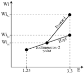
To summarize, a channel flow of a dilute polymer solution between two widely spaced cylinders hindering the flow is an important paradigm of an unbounded flow in the case of a channel wall being located sufficiently far from the cylinders. The quantitative analysis of the elastic instabilities in this flow uncovers a rather general sequence of two bifurcations resulting from the breaking of time-reversal symmetry as the first and mirror symmetry as the second, which are associated with two order parameters: and , respectively. The former experiments and simulations for similar conditions but for closely spaced cylinders have found only the first transition. So can be considered as the second control parameter, which reducing from 3.3 to 1.25 leads to elimination of the second instability. The latter suggests that the codimension-2 point, where both order parameters approach zero, exists between these two values. It is a general case in a large variety of nonequilibrium systems cross . However, the striking and unexpected result is the discovery of the mechanism of the vorticity growth due to an increase of the vortex length at the preserved streamline curvature in a viscoelastic fluid flow, which is in sharp contrast to the well-known suppression of the vorticity in a Newtonian fluid flow by polymer additives cadot ; goldburg .
We thank Guy Han and Yuri Burnishev for technical support. This work was partially supported by grants from Israel Science Foundation and Volkswagen Foundation via the Lower Saxony Ministry of Science and Culture Cooperation (Germany).
References
- (1) A. Groisman and V. Steinberg, Nature 405, 53 (2000).
- (2) V. Steinberg, C. R. Physique 10, 728 (2009).
- (3) A. Groisman, V. Steinberg, Nature 410, 905 (2001).
- (4) A. Groisman and V. Steinberg, New J. Phys. 6, 29 (2004).
- (5) A. Fouxon, V. Lebedev, Phys. Fluids 15, 2060 (2003).
- (6) S. Berti, A. Bistagnino, G. Boffetta, A. Celani, and S. Musacchio, Phys. Rev. E 77, 055306(R) (2008).
- (7) S. Berti, G. Boffetta, Phys. Rev. E 82, 036314 (2010).
- (8) H. Yatou, Phys. Rev. E 82, 036310 (2010).
- (9) N. Liu and B. Khomami, J. Fluid Mech. 737, R4 (2013).
- (10) M. Grilli, A. Vázquez-Quesada, M. Ellero, Phys. Rev. Lett. 110, 174501 (2013).
- (11) T. Burghelea, E. Segre, V. Steinberg, Phys. Rev. Lett. 96, 214502 (2006).
- (12) T. Burghelea, E. Segre, V. Steinberg, Phys. Fluids 19, 053104 (2007).
- (13) Y. Jun, V. Steinberg, Phys. Rev. E 84, 056325 (2011).
- (14) Y. Jun and V. Steinberg, Phys. Rev. Lett. 102, 124503 (2009).
- (15) Y. Liu and V. Steinberg, Europhys. Lett. 90, 44002 (2010).
- (16) R. B. Bird, R. C. Armstrong, and O. Hassager, Dynamics of polymer liquids: Fluid mechanics ( edition, Vols. 1 & 2), John Wiley & Sons.
- (17) D. F. James, Annu. Rev. Fluid Mech. 41, 129 (2009).
- (18) M. J. Solomon and S. J. Muller, J. Non-Newtonian Fluid Mech. 62, 81 (1996).
- (19) B. Yang and B. Khomami, J. Non-Newtonian Fluid Mech. 82, 429 (1999).
- (20) G. H. McKinley, R. C. Armstrong, and R. A. Brown, Phil. Trans. R. Soc. Lond. A 344, 265 (1993).
- (21) S. Kenney, K. Poper, G. Chapagain, G. F. Christopher, Rheol Acta 52, 485 (2013).
- (22) B. Khomami and L. D. Moreno, Rheol. Acta 36, 367 (1997).
- (23) K. Arora, R. Sureshkumar, B. Khomami, J. Non-Newtonian Fluid Mech. 108, 209 (2002).
- (24) A. Varshney, E. Afik, Y. Kaplan and V. Steinberg, Soft Matter 12, 2186 (2016).
- (25) A. Vázquez-Quesada, M. Ellero, J. Non-Newtonian Fluid Mech. 167-168, 1 (2012).
- (26) M. C. Cross and P. C. Hohenberg, Rev. Mod. Phys. 65, 851(1993).
- (27) Y. Liu, Y. Jun, V. Steinberg, J. Rheol. 53, 1069 (2009).
- (28) W. Thielicke and E. Stamhius, J. Open Research Software 2, e30, (2014).
- (29) See Supplemental Material for movies and figures.
- (30) L. Moody, Transactions of the ASME 66, 671 (1944).
- (31) A. Groisman and V. Steinberg, Phys. Rev. Lett. 78, 1460 (1997).
- (32) O. Cadot and M. Lebey, Phys. Fluids 11, 494 (1999).
- (33) J. R. Cressman, Q. Baley, and W. I. Goldburg, Phys. Fluids 13, 867 (2001).
- (34) H. Brand, P. C. Hohenberg, and V. Steinberg, Phys. Rev. A 30, 2548 (1984).
- (35) A. Groisman and V. Steinberg, Phys. Rev. Lett. 77, 1480–1483 (1996).