Low spin wave damping in the insulating chiral magnet Cu2OSeO3
Abstract
Chiral magnets with topologically nontrivial spin order such as Skyrmions have generated enormous interest in both fundamental and applied sciences. We report broadband microwave spectroscopy performed on the insulating chiral ferrimagnet Cu2OSeO3. For the damping of magnetization dynamics we find a remarkably small Gilbert damping parameter of about at 5 K. This value is only a factor of 4 larger than the one reported for the best insulating ferrimagnet yttrium iron garnet. We detect a series of sharp resonances and attribute them to confined spin waves in the mm-sized samples. Considering the small damping, insulating chiral magnets turn out to be promising candidates when exploring non-collinear spin structures for high frequency applications.
pacs:
76.50.+g, 74.25.Ha, 4.40.Az, 41.20.JbThe development of future devices for microwave applications, spintronics and magnonics Zutic and Dery (2011); Krawczyk and Grundler (2014); Chumak et al. (2015) requires materials with a low spin wave (magnon) damping. Insulating compounds are advantageous over metals for high-frequency applications as they avoid damping via spin wave scattering at free charge carriers and eddy currents Gurevich and Melkov (1996); Sparks (1964). Indeed, the ferrimagnetic insulator yttrium iron garnet (YIG) holds the benchmark with a Gilbert damping parameter at room temperature Serga et al. (2010); Klingler et al. (2017). During the last years chiral magnets have attracted a lot of attention in fundamental research and stimulated new concepts for information technology Fert et al. (2013); Nagaosa and Tokura (2013). This material class hosts non-collinear spin structures such as spin helices and Skyrmions below the critical temperature and critical field Mühlbauer et al. (2009); Yu et al. (2010); Seki et al. (2012a). Additionally, Dzyaloshinskii-Moriya interaction (DMI) is present that induces both the Skyrmion lattice phase and nonreciprocal microwave characteristics Seki et al. (2016). Low damping magnets offering DMI would generate new prospects by particularly combining complex spin order with long-distance magnon transport in high-frequency applications and magnonics Mochizuki and Seki (2015); Garst et al. (2017). At low temperatures, they would further enrich the physics in magnon-photon cavities that call for materials with small to achieve high-cooperative magnon-to-photon coupling in the quantum limit Huebl et al. (2013); Tabuchi et al. (2014); Zhang et al. (2014); Goryachev et al. (2014).
In this work, we investigate the Gilbert damping in Cu2OSeO3, a prototypical insulator hosting Skyrmions Kohn (1977); Belesi et al. (2010); Adams et al. (2012); Seki et al. (2012b). This material is a local-moment ferrimagnet with K and magnetoelectric coupling Seki et al. (2012c) that gives rise to dichroism for microwaves Okamura et al. (2013, 2015); Mochizuki (2015). The magnetization dynamics in Cu2OSeO3 has already been explored Onose et al. (2012); Schwarze et al. (2015); Seki et al. (2016). A detailed investigation on the damping which is a key quality for magnonics and spintronics has not yet been presented however. To evaluate we explore the field polarized state (FP) where the two spin sublattices attain the ferrimagnetic arrangementBelesi et al. (2010). Using spectra obtained by two different coplanar waveguides (CPWs), we extract a minimum =(9.9 4.1)10-5 at 5 K, i.e. only about four times higher than in YIG. We resolve numerous sharp resonances in our spectra and attribute them to modes that are confined modes across the macroscopic sample and allowed for by the low damping. Our findings substantiate the relevance of insulating chiral magnets for future applications in magnonics and spintronics.
From single crystals of Cu2OSeO3 we prepared two bar-shaped samples exhibiting different crystallographic orientations. The samples had lateral dimensions of . They were positioned on CPWs that provided us with a dynamic magnetic field induced by a sinusoidal current applied to the signal surrounded by two ground lines. We used two different CPWs with either a broad SWM or narrow signal line width of = 1 mm or 20 m, respectively sup . The central long axis of the rectangular Cu2OSeO3 rods was positioned on the central axis of the CPWs. The static magnetic field was applied perpendicular to the substrate with and for sample S1 and S2, respectively. The direction of defined the -direction. The dynamic field component provided the relevant torque for excitation. Components did not induce precessional motion in the FP state of Cu2OSeO3. We recorded spectra by a vector network analyzer using the magnitude of the scattering parameter . We subtracted a background spectrum recorded at 1 T to enhance the signal-to-noise ratio (SNR) yielding the displayed . In Ref. Klingler et al. (2017), Klingler et al. have investigated the damping of the insulating ferrimagnet YIG and found that Gilbert parameters evaluated from both the uniform precessional mode and standing spin waves confined in the macroscopic sample provided the same values.
For Cu2OSeO3 we evaluated in two waysWei et al. (2015). When extracting the linewidth for different resonance frequencies , the Gilbert damping parameter was assumed to vary according to Heinrich et al. (1985); Kalarickal et al. (2006)
| (1) |
where is the gyromagnetic factor and the contribution due to inhomogeneous broadening. Equation (1) is valid when viscous Gilbert damping dominates over scattering within the magnetic subsystem Lenz et al. (2006). When performing frequency-swept measurements at different fields , the obtained linewidth was considered to scale linearly with the resonance frequency as Patton (1968)
| (2) |
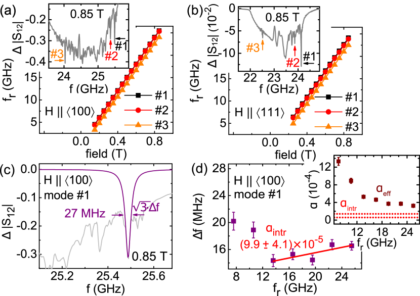
with the inhomogeneous broadening . The conversion from Eq. (1) to Eq. (2) is valid when scales linearly with and is applied along a magnetic easy or hard axis of the material Kuanr et al. (2005); Farle and Zabel (2013). In Fig. 1 (a) to (d) we show spectra recorded in the FP state of the material using the two different CPWs. For the same applied field we observe peaks residing at higher frequency for compared to . From the resonance frequencies, we extract the cubic magnetocrystalline anisotropy constant J/m3 for Cu2OSeO3 sup . The magnetic anisotropy energy is found to be extremal for and reflecting easy and hard axes, respectively sup . The saturation magnetization of Cu2OSeO3 amounted to T at 5 KAdams et al. (2012).
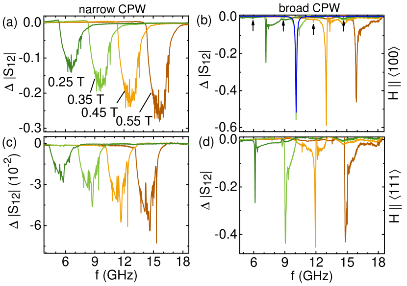
Figure 1 summarizes spectra taken with two different CPWs on two different Cu2OSeO3 crystals exhibiting different crystallographic orientation in the field . For the narrow CPW [Fig. 1 (a) and (c)], we observed a broad peak superimposed by a series of resonances that all shifted to higher frequencies with increasing . The field dependence excluded them from being noise or artifacts of the setup. Their number and relative intensities varied from sample to sample and also upon remounting the same sample in the cryostat (not shown). They disappeared with increasing temperature but the broad peak remained. For the broad CPW [Fig. 1 (b) and (d)], we measured pronounced peaks whose linewidths were significantly smaller compared to the broad peak detected with the narrow CPW. We resolved resonances below the large peaks [arrows in Fig. 1 (b)] that shifted with and exhibited an almost field-independent frequency offset from the main peaks that we will discuss later. It is instructive to first follow the orthodox approach and analyze damping parameters from modes reflecting the excitation characteristics of the CPW Schwarze et al. (2015). Second, we follow Ref. Klingler et al. (2017) and analyze confined modes.
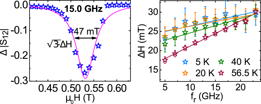
Lorentz curves (blue) were fitted to the spectra recorded with the broad CPW to determine resonance frequencies and linewidths. Note that the corresponding linewidths were larger by a factor of compared to the linewidth that is conventionally extracted from the imaginary part of the scattering parameters Stancil and Prabhakar (2009). The extracted linewidths were found to follow linear fits based on Eq. (2) at different temperatures (details are shown in Ref. sup ). In Fig. 2 (a) we show a resonance curve that was obtained as a function of taken with the narrow CPW at 15 GHz. The curve does not show sharp features as was varied in finite steps (symbols). The linewidth (symbols) is plotted in Fig. 2 (b) for different resonance frequencies and temperatures. The data are well described by linear fits (lines) based on Eq. (1). Note that the resonance peaks measured with the broad CPW were extremely sharp. The sharpness did not allow us to analyze the resonances as a function of . We refrained from fitting the broad peaks of Fig. 1 (a) and (c) (narrow CPW) as they showed a clear asymmetry attributed to the overlap of subresonances at finite wavevector , as will be discussed below.
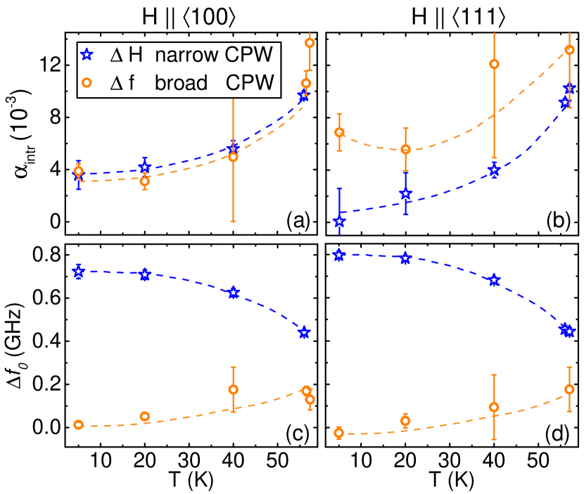
In Fig. 3 (a) and (b) we compare the parameter obtained from both different CPWs (circles vs. stars) and the two evaluation routes 111We call it at this point as the parameter is extracted from linear slopes. Later we will show that standing spin waves provide the lowest . For [Fig. 3 (a)], between 5 and 20 K the lowest value for amounts to (3.7 0.4)10-3. This value is three times lower compared to preliminary data presented in Ref. Schwarze et al. (2015). Beyond 20 K the damping is found to increase. For [Fig. 3 (b)] we extract (0.6 0.6)10-3 as the smallest value. Note that these values for still contain an extrinsic contribution and thus represent upper bounds for Cu2OSeO3, as we will show later. For the inhomogeneous broadening in Fig. 3 (c) and (d) the datasets are consistent (we have used the relation to convert into ). We see that increases with and is small for the broad CPW, independent of the crystallographic direction of . For the narrow CPW the inhomogeneous broadening is largest at small and then decreases by about 40 % up to about 50 K. Note that a CPW broader than the sample is assumed to excite homogeneously at Iguchi et al. (2015) transferring a wave vector to the sample. Accordingly we ascribe the intense resonances of Fig. 1 (b) and (d) to . Using = 6 GHz and = at 5 K [Fig. 3 (a)], we estimate a minimum relaxation time of ns.
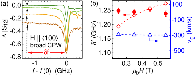
In the following, we examine in detail the additional sharp resonances that we observed in spectra of Fig. 1. In Fig. 1 (b) taken with the broad CPW for , we identify sharp resonances that exhibit a characteristic frequency offset with the main resonance at all fields (black arrows). We illustrate this in Fig. 4(a) in that we shift spectra of Fig. 1 (b) so that the positions of their main resonances overlap. The additional small resonances (arrows) in Fig. 1 (b) are well below the uniform mode. This is characteristic for backward volume magnetostatic spin waves (BVMSWs). Standing waves of such kind can develop if they are reflected at least once at the bottom and top surfaces of the sample. The resulting standing waves exhibit a wave vector , with order number and sample thickness mm. The BVMSW dispersion relation of Ref. Seki et al. (2016) provides a group velocity km/s at [triangles in Fig. 4 (b)]. Hence, the decay length amounts to 2 mm considering ns. This is larger than twice the relevant lateral sizes, thereby allowing standing spin wave modes to form in the sample. Based on the dispersion relation of Ref. Seki et al. (2016), we calculated the frequency splitting [open diamonds in Fig. 4 (b)] assuming and mm for the sample width defined in Ref. Seki et al. (2016). Experimental values (filled symbols) agree with the calculated ones (open symbols) within about 60 MHz. In case of the narrow CPW, we observe even more sharp resonances [Fig. 1 (a) and (c)]. A set of resonances was reported previously in the field-polarized phase of Cu2OSeO3 Kobets et al. (2010); Maisuradze et al. (2012); Onose et al. (2012); Okamura et al. (2015). Maisuradze et al. assigned secondary peaks in thin plates of Cu2OSeO3 to different standing spin-wave modes Maisuradze et al. (2012) in agreement with our analysis outlined above.
The inhomogeneous dynamic field of the narrow CPW provides a much broader distribution of compared to the broad CPW. This is consistent with the fact that the inhomogeneous broadening is found to be larger for the narrow CPW compared to the broad one [Fig. 3 (c) and (c)]. Under these circumstances, the excitation of more standing waves is expected. We attribute the series of sharp resonances in Fig. 1 (a) and (c) to such spin waves. In Fig. 5 (a) and (b) we highlight prominent and particularly narrow resonances with #1, #2 and #3 recorded with the narrow CPW. We trace their frequencies as a function of for and , respectively. They depend linearly on suggesting a Landé factor at 5 K.
We now concentrate on mode #1 for at 5 K that is best resolved. We fit a Lorentzian lineshape as shown in Fig. 5(c) for 0.85 T, and summarize the corresponding linewidths in Fig. 5(d). The inset of Fig. 5(d) shows the effective damping evaluated directly from the linewidth as suggested in Ref. Schwarze et al. (2015). We find that approaches a value of about 3.5 with increasing frequency. This value includes both the intrinsic damping and inhomogeneous broadening but is already a factor of 10 smaller compared to extracted from Fig. 3 (a). Note that Cu2OSeO3 exhibiting 3.5 outperforms the best metallic thin-film magnet Schoen et al. (2016). To correct for inhomogeneous broadening and determine the intrinsic Gilbert-type damping, we apply a linear fit to the linewidths in Fig. 5(d) at GHz and obtain (9.9 4.1)10-5. For 10.6 GHz the resonance amplitudes of mode #1 were small reducing the confidence of the fitting procedure. Furthermore, at low frequencies, we expect anisotropy to modify the extracted damping, similar to the results in Ref. Silva et al. (1999). For these reasons, the two points at low were left out for the linear fit providing (9.9 4.1)10-5.
We find and the damping parameters of Fig. 3 to increase with . It does not scale linearly for sup . A deviation from linear scaling was reported for YIG single crystals as well and accounted for by the confluence of a low- magnon with a phonon or thermally excited magnon Sparks (1964). In the case of (cf. Fig. 3 (b)) we obtain a clear discrepancy between results from the two evaluation routes and CPWs used. We relate this observation to a misalignment of with the hard axis . The misalignment motivates a field-dragging contribution Farle and Zabel (2013) that can explain the discrepancy. For this reason, we concentrated our standing wave analysis on the case . We now comment on our spectra taken with the broad CPW that do not show the very small linewidth attributed to the confined spin waves. The sharp mode #1 yields MHz near 16 GHz [Fig. 5 (d)]. At 5 K the dominant peak measured at 0.55 T with the broad CPW provides however MHz. obtained by the broad CPW is thus increased by a factor of eight and explains the relatively large Gilbert damping parameter in Fig. 3 (a) and (b). We confirmed this larger value on a third sample with and obtained (3.1 0.3)10-3 sup using the broad CPW. The discrepancy with the damping parameter extracted from the sharp modes of Fig. 5 might be due to the remaining inhomogeneity of over the thickness of the sample leading to an uncertainty in the wave vector in -direction. For a standing spin wave such an inhomogeneity does not play a role as the boundary conditions discretize . Accordingly, Klingler et al. extract the smallest damping parameter of reported so far for the ferrimagnet YIG when analyzing confined magnetostatic modes Klingler et al. (2017).
To summarize, we investigated the spin dynamics in the field-polarized phase of the insulating chiral magnet Cu2OSeO3. We detected numerous sharp resonances that we attribute to standing spin waves. Their effective damping parameter is small and amounts to . A quantitative estimate of the intrinsic Gilbert damping parameter extracted from the confined modes provides even =(9.9 4.1)10-5 at 5 K. The small damping makes an insulating ferrimagnet exhibiting Dzyaloshinskii-Moriya interaction a promising candidate for exploitation of complex spin structures and related nonreciprocity in magnonics and spintronics.
We thank S. Mayr for assistance with sample preparation. Financial support through DFG TRR80, DFG 1143, DFG FOR960, and ERC Advanced Grant 291079 (TOPFIT) is gratefully acknowledged.
References
- Zutic and Dery (2011) I. Zutic and H. Dery, Nat. Mater. 10, 647 (2011).
- Krawczyk and Grundler (2014) M. Krawczyk and D. Grundler, J. Phys.: Condens. Matter 26, 123202 (2014).
- Chumak et al. (2015) A. V. Chumak, V. I. Vasyuchka, A. A. Serga, and B. Hillebrands, Nat. Phys. 11, 453 (2015).
- Gurevich and Melkov (1996) A. G. Gurevich and G. A. Melkov, Magnetization Oscillations and Waves (CRC Press, 1996).
- Sparks (1964) M. Sparks, Ferromagnetic-Relaxation Theory (McGraw-Hill, 1964).
- Serga et al. (2010) A. A. Serga, A. V. Chumak, and B. Hillebrands, Journal of Physics D: Applied Physics 43, 264002 (2010).
- Klingler et al. (2017) S. Klingler, H. Maier-Flaig, C. Dubs, O. Surzhenko, R. Gross, H. Huebl, S. T. B. Goennenwein, and M. Weiler, Applied Physics Letters 110, 092409 (2017), http://dx.doi.org/10.1063/1.4977423 .
- Fert et al. (2013) A. Fert, V. Cros, and J. Sampaio, Nat. Nanotechn. 8, 152 (2013).
- Nagaosa and Tokura (2013) N. Nagaosa and Y. Tokura, Nat. Nanotechn. 8, 899 (2013).
- Mühlbauer et al. (2009) S. Mühlbauer, B. Binz, F. Jonietz, C. Pfleiderer, A. Rosch, A. Neubauer, R. Georgii, and P. Böni, Science 323, 915 (2009).
- Yu et al. (2010) X. Z. Yu, Y. Onose, N. Kanazawa, J. H. Park, J. H. Han, Y. Matsui, N. Nagaosa, and Y. Tokura, Nature (London) 465, 901 (2010).
- Seki et al. (2012a) S. Seki, X. Z. Yu, S. Ishiwata, and Y. Tokura, Science 336, 198 (2012a).
- Seki et al. (2016) S. Seki, Y. Okamura, K. Kondou, K. Shibata, M. Kubota, R. Takagi, F. Kagawa, M. Kawasaki, G. Tatara, Y. Otani, and Y. Tokura, Phys. Rev. B 93, 235131 (2016).
- Mochizuki and Seki (2015) M. Mochizuki and S. Seki, J. Physics: Condens. Matter 27, 503001 (2015).
- Garst et al. (2017) M. Garst, J. Waizner, and D. Grundler, https://arxiv.org/abs/1702.03668 (2017).
- Huebl et al. (2013) H. Huebl, C. W. Zollitsch, J. Lotze, F. Hocke, M. Greifenstein, A. Marx, R. Gross, and S. T. B. Goennenwein, Phys. Rev. Lett. 111, 127003 (2013).
- Tabuchi et al. (2014) Y. Tabuchi, S. Ishino, T. Ishikawa, R. Yamazaki, K. Usami, and Y. Nakamura, Phys. Rev. Lett. 113, 083603 (2014).
- Zhang et al. (2014) X. Zhang, C.-L. Zou, L. Jiang, and H. X. Tang, Phys. Rev. Lett. 113, 156401 (2014).
- Goryachev et al. (2014) M. Goryachev, W. G. Farr, D. L. Creedon, Y. Fan, M. Kostylev, and M. E. Tobar, Phys. Rev. Applied 2, 054002 (2014).
- Kohn (1977) K. Kohn, J. Phys. Soc. Jpn 42, 2065 (1977).
- Belesi et al. (2010) M. Belesi, I. Rousochatzakis, H. C. Wu, H. Berger, I. V. Shvets, F. Mila, and J. P. Ansermet, Phys. Rev. B 82, 094422 (2010).
- Adams et al. (2012) T. Adams, A. Chacon, M. Wagner, A. Bauer, G. Brandl, B. Pedersen, H. Berger, P. Lemmens, and C. Pfleiderer, Phys. Rev. Lett. 108, 237204 (2012).
- Seki et al. (2012b) S. Seki, J.-H. Kim, D. S. Inosov, R. Georgii, B. Keimer, S. Ishiwata, and Y. Tokura, Phys. Rev. B 85, 220406 (R) (2012b).
- Seki et al. (2012c) S. Seki, S. Ishiwata, and Y. Tokura, Phys. Rev. B 86, 060403 (2012c).
- Okamura et al. (2013) Y. Okamura, F. Kagawa, M. Mochizuki, M. Kubota, S. Seki, S. Ishiwata, M. Kawasaki, Y. Onose, and Y. Tokura, Nat. Commun. 4, 2391 (2013).
- Okamura et al. (2015) Y. Okamura, F. Kagawa, S. Seki, M. Kubota, M. Kawasaki, and Y. Tokura, Phys. Rev. Lett. 114, 197202 (2015).
- Mochizuki (2015) M. Mochizuki, Phys. Rev. Lett. 114, 197203 (2015).
- Onose et al. (2012) Y. Onose, Y. Okamura, S. Seki, S. Ishiwata, and Y. Tokura, Phys. Rev. Lett. 109, 037603 (2012).
- Schwarze et al. (2015) T. Schwarze, J. Waizner, M. Garst, A. Bauer, I. Stasinopoulos, H. Berger, C. Pfleiderer, and D. Grundler, Nature Mater. 14, 478 (2015).
- (30) Model B4350-30C from Southwest Microwave, Inc., www.southwestmicrowave.com.
- (31) See Supplemental Material at [URL] for experimental details and additional data.
- Wei et al. (2015) Y. Wei, S. L. Chin, and P. Svedlindh, J. Phys. D: Appl. Phys. 48, 335005 (2015).
- Heinrich et al. (1985) B. Heinrich, J. F. Cochran, and R. Hasegawa, J. Appl. Phys. 57 (1985).
- Kalarickal et al. (2006) S. S. Kalarickal, P. Krivosik, M. Wu, C. E. Patton, M. L. Schneider, P. Kabos, T. J. Silva, and J. P. Nibarger, J. Appl. Phys. 99, 093909 (2006).
- Lenz et al. (2006) K. Lenz, H. Wende, W. Kuch, K. Baberschke, K. Nagy, and A. Jánossy, Phys. Rev. B 73, 144424 (2006).
- Patton (1968) C. E. Patton, J. Appl. Phys. 39 (1968).
- Kuanr et al. (2005) B. Kuanr, R. E. Camley, and Z. Celinski, Appl. Phys. Lett. 87, 012502 (2005).
- Farle and Zabel (2013) M. Farle and H. Zabel, Magnetic Nanostructures Spin Dynamics and Spin Transport, Vol. 246 (Springer Tracts in Modern Physics, 2013).
- Stancil and Prabhakar (2009) D. D. Stancil and A. Prabhakar, Spin Waves Theory and Applications (Springer, 2009).
- Note (1) We call it at this point as the parameter is extracted from linear slopes. Later we will show that standing spin waves provide the lowest .
- Iguchi et al. (2015) Y. Iguchi, S. Uemura, K. Ueno, and Y. Onose, Phys. Rev. B 92, 184419 (2015).
- Kobets et al. (2010) M. I. Kobets, K. G. Dergachev, E. N. Khatsko, A. I. Rykova, P. Lemmens, D. Wulferding, and H. Berger, Low Temp. Phys. 36 (2010).
- Maisuradze et al. (2012) A. Maisuradze, A. Shengelaya, H. Berger, D. M. Djokić, and H. Keller, Phys. Rev. Lett. 108, 247211 (2012).
- Schoen et al. (2016) M. A. W. Schoen, D. Thonig, M. L. Schneider, T. J. Silva, H. T. Nembach, O. Eriksson, O. Karis, and J. M. Shaw, Nat. Phys. 12, 839 (2016).
- Silva et al. (1999) T. J. Silva, C. S. Lee, T. M. Crawford, and C. T. Rogers, J. Appl. Phys. 85 (1999).