Large magnetic anisotropy in single crystals
Abstract
In intercalated transition metal dichalcogenide (0.2 x 0.4) single crystals, large magnetic anisotropy is observed. Transport property measurements indicate that heavy Fe-doping leads to a large anisotropy of resistivity (c/ab). A sharp M-H hysteresis curve is observed with magnetic field along c-axis, while a linear magnetization appears with magnetic field applied in the ab-plane. The angular dependent magnetic susceptibility from in-plane to out-of-plane indicates that magnetic moments are strongly pinned along the c-axis in an unconventional manner and the coercive field reaches as large as 6 T at T = 5 K. First-principles calculation clearly suggests that the strong spin-orbital coupling give rise to such a large anisotropy of magnetism. The strong pinning effect of magnetic moments along c-axis makes this material a very promising candidate for the development of spin-aligner in spintronics devices.
pacs:
75.30.Cr,75.30.Gw,75.50.-yTransition metal dichalcogenides have been subject to intensive study due to their rich physical properties as a result of strong electron correlation and electron-phonon coupling. These intriguing compounds share the same characteristics that they are all low dimensional with layered structures, and receptive to intercalation due to van der Waals force between S-M-S layersWhittingham ; Whittingham2 ; Trichet . In this family, people have discovered charge density wave (CDW) order in 1T-ref1 , long range magnetic order in (ferromagnetism)ref2 and (antiferromagnetism)ref3 , and superconductivity in and ref4 ; Morosan ; Wu . Among them, iron-intercalated compounds have been greatly attractive owing to their exotic magnetic properties originating from the interaction between crystal field, electron orbit and local moment of .
Previous works by Cava et al.cava and Ong et al.ong have shown that in (x = 1/4) ions are distributed periodically in a doubled cell of parent compound rather than randomly scattered between layers. Computational results has validated the ferromagnetic transition for x = 0.33Dijkstra . In FexTaS2 system, the magnetic properties of FexTaS2 change from spin glass (x0.2) to ferromagnetism (0.2x0.4)Eibschutz and antiferromagnetism(x0.4)Narita with the increasing of x. For 0.20x0.40, the Curie temperature Tc is non-monotonous with x, Tc=90 K for x=0.2; Tc=163 K for x=0.26; Tc=55 K for x=0.34Eibschutz . The Curie temperature decreases as x further increases. Cheong et al. suggested the nano domains and unqueched orbital moment contribute to the large magnetic anisotropy and magnetoresistance, respectively Choi ; Ko . However, Morosan et al. attributed the large magnetoresistance to disorder Chen . A systematical study on the magnetic and transport properties of , especially the magnetization and transport behaviors under different magnetic fields, are critical to reveal the intrinsic properties of this material. In this paper, we presence the large magnetic anisotropy in the resistivity, magnetic susceptibility and magnetization in FexTaS2 single crystals and elucidate the microscopic origin of such a huge magnetic anisotropy.
The FexTaS2 (0.2x0.40) single crystals were grown by the chemical iodine vapor transport method. Fe (99.5%), Ta (99.5%) and S (99.5%) element powders were mixed and thoroughly ground, then pressed into pellets. The pellets were sealed under vacuum (1.010-2Pa) in a quartz tube ( 13mm150mm) with a small quantity of iodine (10mg/cm-3). The tube was slowly heated to 1000oC in 400 minutes, and the cold end of the tube was kept at 950oC. After ten days, the furnace was cooled to room temperature over a few hours. Finally many high quality plate-like FexTaS2 single crystals were obtained. The single crystals were black and the typical dimension is about 330.3mm3.
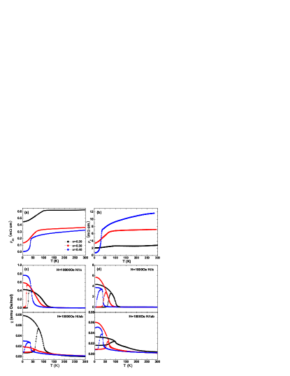
Figs. 1(a) and (b) demonstrates how the resistivity anisotropy evolves with Fe doping. As the dopant Fe increases from 0.2 to 0.4, the electronic resistivity in the ab-plane significantly decreases, while the out-of plane resistivity increases drastically, thus leading to an enhanced anisotropy of . The ferromagnetic phase transition indicated by the kinks in resistivity is gradually suppressed with Fe doping, from 105 K for x=0.2, to 76 K for x=0.3, and 43 K for x=0.4, respectively. Figs. 1(c) and (d) show the temperature dependence of magnetic susceptibility with the applied magnetic field of 10000 Oe and 1000 Oe, respectively. The in-plane susceptibility is significantly smaller than the c-axis susceptibility, unambiguously indicating that the easy axis is perpendicular to the ab-plane, and a large field tends to reduce such magnetic anisotropy. It should be pointed out that the zero field cooled magnetization curve with the magnetic field applied along c-axis reaches almost zero below , while magnetization with the magnetic field applied in the ab-plane can not yields zero susceptibility below . This contrast implies that there exists an anisotropic magnetic energy between the ab-plane and c-axis. These results are consistent with those reported in Ref. Eibschutz
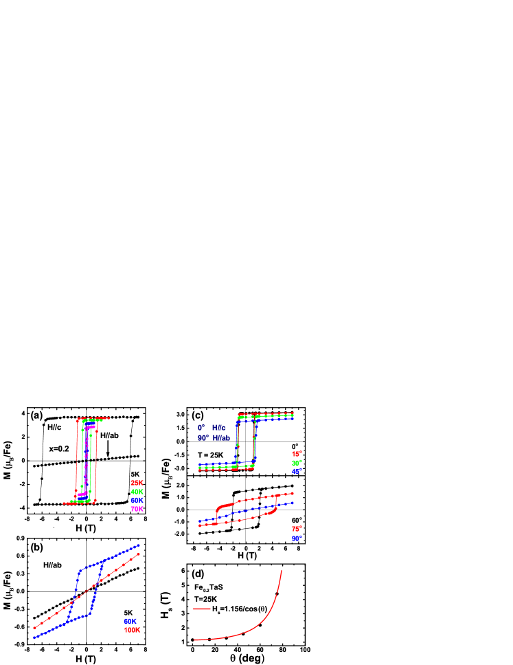
Fig. 2(a) shows the magnetization loops at different temperatures under the magnetic field applied along c-axis of Fe0.2TaS2. Clear M-H loops shows up below the Curie temperature with the external magnetic field applied along the c-axis. The coercive field systematically decreases with increasing the temperature. The most striking features are the large coercive field up to 6 T at 5 K and the sharp magnetic transition to reach saturation magnetization (). Fig. 2(b) shows the evolution of the magnetization () with the external magnetic field applied in ab-plane at different temperatures. There is no M-H loop at 5 K, and the magnetization increases linearly with the magnetic field up to 7 T with a small slope. This behavior suggests that the pinning force along c-axis is so strong at 5 K that only statistical net moment could be observed in the ab-plane magnetization (). When temperature rises to 60 K, the magnetic anisotropy decreases and more local moments from Fe ions are aligned in the ab-plane to form domain, so that a skew M-H loop appears during the magnetizing process as shown in Fig. 2(b). Such a behavior implies that the in-plane magnetic crystal energy is weaker than that along c-axis. As temperature rises to above , the thermal fluctuation becomes dominant, and the magnetization correspondingly follows a linear dependence of the magnetic field and shows a paramagnetic behavior. As shown in Fig. 2(a), the slope of the linear magnetic field dependent is so small that the anisotropy field approximately exceeds 60 T if we extrapolate the linear to the saturation value of . Therefore, the first order anisotropic coefficient /2 is estimated to be about 6.5 meV. As temperature increases, the coercive field and remaining magnetization shrink quickly, suggesting a rapid decrease of .
Fig. 2(c) shows the evolution of magnetization loop with the direction of external magnetic field at T = 25 K. A continuous ’flattened’ loop is observed, and the saturated magnetization continuously decreases and the coercive field monotonously increases with the variation of the applied magnetic field from along the c-axis to the in-plane. The switching field of the magnetization obtained from Fig. 2(c) are plotted in Fig. 2(d), and the evolution of with the direction of the applied magnetic field can be well fitted by the formula =1.156/cos(). This behavior indicates that is almost an ideal single domain ferromagnetic system with the easy axis perpendicular to the ab-plane.
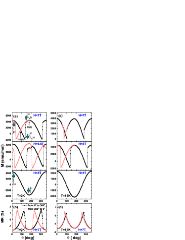
In order to quantify the pinning strength in this system, angle-dependent magnetization and magnetoresistance with the direction of external magnetic field varying from c-axis to ab-plane were carried out, and the results are shown in Fig. 3. As shown in Fig. 3(a), the applied external field up to 5 Tesla still cannot flip the spins at T = 2 K, so that the magnetization behaves exactly in a sinusoid way. As the external magnetic field rises to 6.5 and 7 Tesla, there are clear jumps on magnetization at and relative to c-axis, respectively. In Fig. 3(c), similar behavior persists at T = 15 K. The magnetic field up to 1 T can not flip the spins, while the spin flip takes place with increasing the field up to 3 Tesla. Our data indicates that the critical field of the spin flip decreases with increasing temperature. A pictorial explanation is sketched in Fig. 3(a). The spins of Fe ions are pinned along c-axis at low temperature. When the external magnetic field is rotated, the spin alignment holds until the magnetic energy cos() surpasses the pinning energy , then an 180-degree flip happens for all spins, leading to the sharp jump of magnetization from negative (positive) to positive (negative). Based on the critical angle of the spin flip at certain magnetic field, we can estimate the pinning energy in terms of following relation:
| (1) |
which could be verified for both of the cases at 2 K and 15 K, respectively. The pining energy is 1.24 meV at 2 K, and 0.53 meV at 15 K. gradually decreases with increasing temperature due to thermal fluctuation. Similar magnetoresistance measurement confirms the spin flip under rotating external field from the c-axis to the ab-plane, as shown in Figs. 3(b) and 3(d). The flipping critical angle is exactly the same as those obtained from the angle-dependent magnetization. These results not only confirm the existence of pinning along the c-axis, but also suggest that magnetic scattering is profound in this system. Moreover, as temperature rises, the sharp jump in magnetization become week and finally disappears, closely correlated with the behavior of magnetoresistance. Such a correlation indicates that the magnetic scattering is an indispensable component in the electronic transport and there exsits a strong spin-electron coupling.
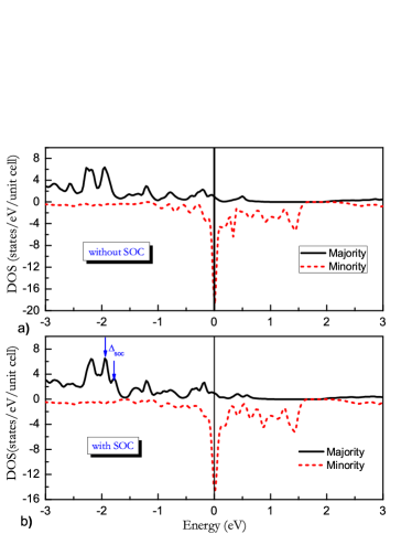
The key to the understanding of these exotic phenomena in system is to clarify the roles of Fe spins and its coupling with environment. In conventional 3d transition metals, the orbital angular momentum is partially or almost fully quenched due to the complete or partial lift of the orbital degeneracy in 3d electronic states, as a result of the presence of low symmetric crystal field. In the present case, our theoretical calculations and analysis show that the intercalated Fe ions are coordinated in a triangular crystalline field of six S ions, the orbital degeneracy of Fe 3d orbitals is partially removed. A crystal field separates the upper two-fold eg levels from lower three-fold degenerate t2g levels with of 1 eV. This leads to an effective orbital angular momentum L = 1, in agreement with Cheong et al.’s result Ko . Considering the Fe spin of S=2 in the Fe 3d4 configuration, we have the total angular momentum of J = 3 for Fe ions. Therefore, the theoretical value of magnetic moment in is about 5 , in good agreement with our and Cava et al.’s cava experimental results. In order to find out the origin of strong pinning of spin alignment along c-axis, we have carried out further first-principles electronic structure calculation, and found considerable effect from the spin-orbital coupling, as shown in Fig. 4. By comparing the density of states (DOS) without and with the spin-orbital coupling, one may find that the spin-orbital coupling brings about a 0.05 eV splitting in the orbital around 2 eV below the Fermi level ( see Figs. 4(a) and 4(b)). The strongly spin-polarized Fermi surface also directly gives rise to the strong field-dependent transport properties. At last, we could infer the magnetic anisotropy parameter to be
| (2) |
which decently agrees with the experimental data of 6.5 meV. We also notice that a recent work suggested the crucial role of electronic correlation Zhu . The first-principles electronic structure calculation confirms that the spin-orbital coupling can induced large magnetic anisotropy and strong spin pinning along c-axis in , the calculated magnetic anisotropy energy is well consistent with the experiment result.
Efficient electrical injection of spin-polarized carriers from a contact into a semiconductor is one of the essential requirements to utilize carrier spin as an operational paradigm for future electronic devices like a spin-LEDFiederling ; Hanbicki ; Liu . Two kinds of spin aligner are used to polarize the spin of the carriers. One is diluted magnetic semiconductor and the other is ferromagnetic metal. The large coercive field and the sharp transition in the c-axis magnetization of can provide as the spin aligner in electrical spin injection in spintronics.
In summary, we have observed large magnetic anisotropy in system. Coercive field as large as 6 T and sharp transition exist in c-axis magnetization. Angle-dependent magnetization at different temperatures from ab-plane to c-axis reveals that the strong pinning along c-axis fits the simple spin-flip model, in favor of the single domain picturecava . Theoretical analysis suggests that the magnetic anisotropy comes from the spin-orbital coupling of Fe ions in the triangular crystal field. Both of first-principles electronic structure calculation and experiment indicate a magnetic anisotropy energy of 7 meV. Our data suggests that can serve as a spin aligner in electrical spin injection in spintronicsFiederling . The spontaneous strong spin polarization in this material can also be adopted as a reliable spin current source.
References
- (1) M. S. Whittingham, Prog. Solid State Chem. 12, 41 (1978).
- (2) M. S. Whittingham, J. Electrochem. Soc. 123, 315 (1976).
- (3) L. Trichet, J. Rouxel, and M. M. Pouchard, J. Solid State Chem. 14, 283 (1975).
- (4) D. R. Karecki, and B. P. Clayman, Phys. Rev. B 19, 6367 (1979).
- (5) S. S. P. Parkin and R. H. Friend, Phil. Mag. 41 65 (1980).
- (6) M. A. Buhannic, P. Colombet, M. Danot, and G. Calvarin, J. Solid State Chem. 69, 280 (1987).
- (7) A. Schlicht, M. Schwenker, W. Biberacher, and A. Lerf, J. Phys. Chem. B 105, 4867 (2001).
- (8) E. Morosan, H. W. Zandbergen, B. S. Dennis, J. W. G. Bos, Y. Onose, T. Klimczuk, A. P. Ramirez, N. P. Ong, and R. J. Cava, Nat. Phys. 2, 544 (2006).
- (9) G. Wu, H. X. Yang, L. Zhao, X. G. Lou, T.Wu, G. Y. Wang, and X. H. Chen, Phys. Rev. B 76, 024513 (2007).
- (10) E. Morosan, H. W. Zandbergen, Lu Li, Minhyea Lee, J. G. Checkelsky, M. Heinrich, T. Siegrist, N. P. Ong, and R. J. Cava, Phys. Rev. B 75, 104401 (2007).
- (11) J. G. Checkelsky, M. H. Lee, E. Morosan, R. J. Cava, and N. P. Ong, Phys. Rev. B 77, 014433 (2008).
- (12) J. Dijkstra, P. J. Zijlema, C. F. van Bruggen, C. Haas, and R. A. de Groot, J. Phys.: Condens. Matt. 1, 6363 (1989).
- (13) M. Eibschtz, S. Mahajan, F. J. DiSalvo, G. W. Hull, and J. V. Waszczak, J. Appl. Phys. 52, 2098 (1981).
- (14) K.-T. Ko, K. Kim, S. B. Kim, H.-D. Kim, J.-Y. Kim, B. I. Min, J.-H. Park, F.-H. Chang, H.-J. Lin, A. Tanaka, and S-W. Cheong, Phys. Rev. Lett. 107, 247201 (2011).
- (15) Y. J. Choi, S. B. Kim, T. Asada, S. Park, W. D Wu, Y. Horibe, and S-W. Cheong, Europhys. Lett. 86, 37012 (2009).
- (16) C.-W. Chen, S. Chikara, V. S. Zapf, and E. Morosan, Phys. Rev. B 94, 054406 (2016).
- (17) H. Narita, H. Ikuta, H. Hinode, T. Uchida, T. Ohtani, and M. Wakihara, J. Solid State Chem. 108, 148 (1994).
- (18) V. Loganathan, J.-X. Zhu, and A. H. Nevidomskyy, arXiv:1605.07141 (2016).
- (19) R. Fiederling, M. Keim, G. Reuscher, W. Ossau, G. Schmidt, A. Waag, and L. W. Molenkamp, Nature 402, 787 (1999).
- (20) A. T. Hanbicki, B. T. Jonker, G. Itskos, G. Kioseoglou, and A. Petrou, Appl. Phys. Lett. 80, 1240 (2002).
- (21) B. L. Liu, M. Senesa, S. Couderca, J. F. Boboa, X. Mariea, T. Amanda, C. Fontaineb, and A. Arnoult, Physica E, 17, 358 (2003).
Acknowledgements This work is supported by the National Key RD Program of the MOST of China (Grant No. 2016YFA0300201), the Nature Science Foundation of China (Grant No: 11474287), Hefei Science Center CAS (2016HSC-IU001) and the “Strategic Priority Research Program” of the Chinese Academy of Sciences (grant no. XDB04040100).