Casimir free energy of dielectric films: Classical limit, low-temperature behavior and control
Abstract
The Casimir free energy of dielectric films, both free-standing in vacuum and deposited on metallic or dielectric plates, is investigated. It is shown that the values of the free energy depend considerably on whether the calculation approach used neglects or takes into account the dc conductivity of film material. We demonstrate that there are the material-dependent and universal classical limits in the former and latter cases, respectively. The analytic behavior of the Casimir free energy and entropy for a free-standing dielectric film at low temperature is found. According to our results, the Casimir entropy goes to zero when the temperature vanishes if the calculation approach with neglected dc conductivity of a film is employed. If the dc conductivity is taken into account, the Casimir entropy takes the positive value at zero temperature, depending on the parameters of a film, i.e., the Nernst heat theorem is violated. By considering the Casimir free energy of SiO2 and Al2O3 films deposited on a Au plate in the framework of two calculation approaches, we argue that physically correct values are obtained by disregarding the role of dc conductivity. A comparison with the well known results for the configuration of two parallel plates is made. Finally, we compute the Casimir free energy of SiO2, Al2O3 and Ge films deposited on high-resistivity Si plates of different thicknesses and demonstrate that it can be positive, negative and equal to zero. The effect of illumination of a Si plate with laser light is considered. Possible applications of the obtained results to thin films used in microelectronics are discussed.
pacs:
77.55.-g, 77.22.ChKeywords: Casimir free energy, dielectric films, Nernst heat theorem, dc conductivity.
1 Introduction
The fluctuation-induced phenomena and, specifically, the van der Waals and Casimir forces, play a progressively increasing role in many topics of physics, chemistry and biology (see the monographs [1, 2] and reviews [3, 4, 5, 6]. They are responsible for interaction of electrically neutral, but polarizable, particles with material surfaces [7, 8, 9, 10], find applications in nanoscience [11, 12, 13, 14], play important role in many effects of condensed matter physics [15, 16, 17, 18, 19, 20], and are even used in elementary particle physics for constraining some theoretical predictions beyond the standard model [21, 22, 23].
When considering the Casimir interaction, the configuration of two material bodies interacting through a vacuum gap is in most common use. Thus, the fundamental theory of the van der Waals and Casimir forces (the Lifshitz theory) was originally formulated for two parallel semispaces separated by some distance [1, 2, 24]. Later on, this theory was generalized for the cases of arbitrarily many plane parallel material layers and closely spaced surfaces of any geometrical shape [2, 6].
Another system described by the Lifshitz theory is a free-standing or deposited on a thick plate material film. Electromagnetic fluctuations result in some Casimir free energy of a film, which should be taken into account in the balance of energies responsible for its stability. This problem was formulated more than 80 years ago by Derjaguin and has been investigated using several approximate approaches in physical chemistry of surfaces [25].
Recently it was shown that the Casimir free energy of both nonmagnetic and magnetic metallic films calculated rigorously in the framework of the Lifshitz theory differ considerably depending on whether the Drude or the plasma model is used for extrapolation of the optical data for the complex index of refraction to zero frequency [26, 27, 28]. It is well known that there is an outstanding problem in the Lifshitz theory [2, 3, 6]. The point is that the low-frequency response of metals to classical electromagnetic fields is commonly described by the dissipative Drude model. However, the predictions of the Lifshitz theory are excluded by the experimental data of all precise experiments on measuring the Casimir force between two metallic test bodies if this model is used to describe the response of metals to a fluctuating field [29, 30, 31, 32, 33, 34, 35, 36]. The same experiments are in a very good agreement with the Lifshitz theory if the lossless plasma model is used for extrapolation of the optical data of metals to zero frequency [29, 30, 31, 32, 33, 34, 35, 36, 37].
It must be emphasized that in all precise experiments on measuring the absolute values of the Casimir force [29, 30, 31, 32, 33, 34, 35] (or force gradients) at separations below m theoretical predictions of the Lifshitz theory using the Drude and the plasma models differ by only a few percent. The difference in theoretical predictions by up to a factor of two is reached only at separations of a few micrometers, where the absolute value of the measured force becomes too small. Large differences in the predictions of both approaches are reached in the recently proposed [38, 39, 40] differential force measurements, but in the experiments of this kind the measured force signal is also rather low [36]. Unlike the configuration of two metallic plates separated with a gap, the absolute values of the Casimir free energy and pressure of metallic films, as thin as of 50 or 100 nm thickness, can differ by the factors of hundreds and even thousands when the calculation approaches using the Drude and the plasma models are used [26, 27, 28]. Thus, the Drude-plasma dilemma becomes extremely important not only from the theoretical point of view, but for important technological applications as well.
In this paper, we investigate the Casimir free energy of dielectric films, either free-standing or deposited on metallic or dielectric plate. It is shown that, in some analogy to already investigated case of metallic films [26, 27, 28], the Lifshitz theory leads to considerably different results depending on whether one takes into account the conductivity of film material at nonzero temperature or omits it in calculations. Similar result has been obtained previously in calculations of the measured Casimir forces between two bodies separated by a vacuum gap with one of them made of dielectric material [41, 42, 43, 44, 45], but the differences in theoretical predictions were much less than we find here for a dielectric film. It was shown that the Lifshitz theory is excluded by the measurement data if the conductivity at a constant current (i.e., the dc conductivity) is taken into account in computations. If the dc conductivity is omitted in computations, the Lifshitz theory was found to be in a good agreement with the experimental data [41, 42, 43, 44, 45]. One more experiment of this type was proposed in [46].
Furthermore, for two plates or for an atom above a plate it has been shown [47, 48, 49, 50, 51] that the Lifshitz theory with included dc conductivity violates the third law of thermodynamics (the Nernst heat theorem), whereas the same theory is in perfect agreement with thermodynamics when the dc conductivity is omitted. According to the Nernst heat theorem, in thermal equilibrium the entropy of a physical system must go to the universal constant, which does not depend on the parameters of a system, when the temperature vanishes [52, 53]. It is conventional to put this constant equal to zero. The rigorous proof of the Nernst heat theorem is given in the framework of quantum statistical physics [52, 53]. In so doing, entropy at zero temperature proves to be proportional to the logarithm of the number of states with the lowest energy. For the nondegenerate dynamical state of lowest energy the entropy at zero temperature is equal to zero. Note that for metals with perfect crystal lattices the Lifshitz theory violates the Nernst theorem when the Drude model is used and satisfies it if the plasma model is employed [54, 55, 56, 57, 58]. For metals with impurities the Nernst heat theorem is satisfied because at very low temperature the Casimir entropy abruptly jumps to zero starting from the negative value [59]. This, however, does not solve the problem because the crystal with perfect crystal lattice is a truly equilibrium system with a nondegenerate ground state, and the Nernst heat theorem must be satisfied in this case.
Here, we devote main attention to the consideration of the Casimir free energy rather than the Casimir pressure of a film. The point is that the film stability is determined by the sign of the total film free energy to which the Casimir free energy is one of important contributions. The film stability is reached when the total free energy is negative. Thus, we investigate in detail when the Casimir contribution to the total free energy changes its sign (under this condition the Casimir pressure changes its sign as well).
According to our results, the Casimir free energy of dielectric film reaches the classical limit irrespective of whether it is described with included or omitted dc conductivity. In the latter case, the Casimir free energy goes to the universal limit with increasing film thickness, whereas in the former the limiting value of the Casimir free energy depends on the film material. Unlike the case of two dielectric plates separated with a vacuum gap, the classical limit is already reached for relatively thin films of less than m thickness at room temperature.
We find asymptotic expressions for the Casimir free energy of dielectric films at low temperature. It is shown that for a film made of perfect dielectric (i.e., having zero electric conductivity at all temperatures) the Casimir entropy satisfies the Nernst heat theorem. If the dc conductivity, which is inherent to any dielectric material at nonzero temperature, is included in calculations, the Casimir entropy of a film takes the positive value at zero temperature. This value depends on the film parameters, i.e., the Nernst heat theorem is violated. We also perform numerical computations for the Casimir free energy of dielectric films, both free standing and deposited on metallic plate, and show that it takes negative and positive values, respectively.
Finally, the possibilities to control the Casimir free energy of dielectric films deposited on a dielectric plate are investigated. For this purpose, the free energies of silica, sapphire and germanium films deposited on silicon plates of different thickness are computed. The role of illumination of a silicon plate with laser light is considered. It is shown that the Casimir free energy of a film can take both negative and positive values, but an illumination of a plate makes it positive with exception of only very thin Ge films.
The obtained results can be used in numerous applications of novel dielectric films in optics and advanced microelectronics including better understanding of physical principles of thin film deposition [60].
2 General formalism for a dielectric film deposited on material plate
In this section, we formulate several results of the Lifshitz theory in the form convenient for application to thin films. We also find the classical limit for the free energy of a free-standing film and demonstrate its dependence on an inclusion of the dc conductivity of dielectric material.
2.1 Lifshitz-type formula for a film
All the configurations of our interest can be considered as particular cases of a system consisting of the dielectric film of thickness with dielectric permittivity deposited on a material plate of thickness with dielectric permittivity . We assume that this system is at temperature in vacuum in thermal equilibrium with an environment. Then, the Casimir free energy of a film per unit area is given by the following Lifshits-type formula [2, 24]:
| (1) |
Here, is the Boltzmann constant, is the magnitude of the projection of the wave vector on the plane of a film, with are the Matsubara frequencies, the prime on the summation sign in multiplies the term with by 1/2, and the sum in makes a summation on the transverse magnetic (TM) and transverse electric (TE) polarizations of the electromagnetic field.
The reflection coefficients on the boundary surface between a film and a vacuum are defined as
| (2) |
where and
| (3) |
The reflection coefficients on the boundary surface between a film and a plate of finite thickness are given by
| (4) |
where the reflection coefficients on the plane between a film and a semispace, made of the same material as a plate, take the form
| (5) |
and
| (6) |
The remaining coefficients in (4) are given by (2) with a replacement of the index (film) with the index (plate).
Thick plates can be considered as semispaces. The Casimir free energy of a dielectric film deposited on a thick plate is obtained from (1) and (4) by limiting transition . In this case we have
| (7) |
For a free-standing film in vacuum one has and
| (8) |
Below we make the asymptotic expansions and numerical computations using (1)–(8). For this purpose it is convenient to introduce the dimensionless variables
| (9) | |||
where an important parameter is given by
| (10) |
In terms of this variables the Casimir free energy of a film takes the form
| (11) |
Here, the reflection coefficients are
| (12) |
The reflection coefficients expressed in terms of the variables (9) are given by (4) where and are replaced with and ,
| (13) |
the reflection coefficients are obtained from (12) by a replacement of the index for and
| (14) |
We consider, first, the Casimir free energy (11) in the limiting case of large separations (high temperatures). For the configuration of two parallel plates separated with a gap, the main contribution to the Casimir free energy does not depend on in this case, i.e., becomes classical.
2.2 Classical limit
It is well known [2] that at sufficiently high temperatures
| (15) |
the zero-frequency term of the Lifshitz formula (11) gives the dominant contribution to the Casimir free energy, whereas contributions of all nonzero Matsubara frequencies become exponentially small. The condition (15) can be rewritten as , i.e., as a restriction on the separation between two parallel plates or on a film thickness depending on the meaning of the parameter .
For a free-standing dielectric film in vacuum with finite static dielectric permittivity the zero-frequency contribution to the Casimir free energy (11) is given by
| (16) |
where, according to (8) and (12),
| (17) |
Expanding the logarithm in (16) in power series and integrating, one arrives at
| (18) |
where is the polylogarithm function.
Under the condition (15) it is easy also to estimate the contribution of the first Matsubara frequency to the Casimir free energy of dielectric film. For this purpose, we take into account that the TE contribution remains negligibly small and obtain from (11)
| (19) |
To obtain an order of magnitude estimation, it is safe to replace with and with . Then, (19) results in
| (20) |
Under the condition (15) one can preserve only the first term in the series expansion of the logarithm and find
| (21) |
In the last approximate equality we have taken into account that due to the condition (15) and definition of (9) it holds . Note that the quantity (21) is not classical because depends on .
Repeating similar estimations for the well known case of two thick parallel plates separated with a vacuum gap, one arrives at the familiar result
| (22) |
for the contribution of the first Matsubara frequency and to the same result, as in (18), for the zero-frequency contribution.
We are now in a position to compare two minimum values of such that the classical limit is already reached for a pair of plates separated with a vacuum gap and for a free-standing dielectric film made of the same material. Let for two plates one can neglect by the contribution of the first Matsubara frequency (22) for all exceeding (at K this is the case at m, i.e., ). Then, by comparing (21) and (22), we conclude that for a dielectric film the contribution of the first Matsubara frequency becomes negligibly small, as compared to the zero-frequency contribution (18), at some satisfying the condition
| (23) |
i.e., at . Therefore, for a dielectric film at K the classical limit is reached for rather thin films of m thickness. Numerical computations below demonstrate a very good agreement with this result.
In the above it was assumed that the static dielectric permittivity of film material is finite. It is common knowledge, however, that at any nonzero temperature all dielectric materials possess some nonzero conductivity. With account of this conductivity, the dielectric permittivity of film material takes the form [2, 61]
| (24) |
where is the static conductivity which goes to zero exponentially fast with vanishing temperature.
Substituting (24) in (11), for the zero-frequency contribution to the Casimir free energy of a free-standing dielectric film one obtains
| (25) |
where is the Riemann zeta function. This is the same result which is known for two plates separated by a gap, irrespective of whether they are made of a metal described by the Drude model or dielectric with taken into account dc conductivity. In doing so, the estimations of the role of first Matsubara frequency in (21) and (22) remain unchanged.
One can conclude that the Casimir free energy of a dielectric film reaches the classical limit, no matter whether the dc conductivity is included in calculations or not. If the dc conductivity is omitted, the classical limit (18) is different for different dielectrics. If the dc conductivity is included in calculations, the classical limit (25) does not depend on a specific material. In all cases, however, the classical limit is reached for thinner films than for two plates separated by a gap of the same width as the film thickness. We note also that in the case of metallic films described by the plasma model the Casimir free energy does not reach the classical limit at any film thickness and temperature [26, 27, 28].
3 Nernst heat theorem for a free-standing dielectric film
Taking into account that the inclusion and neglect of the dc conductivity lead to significantly different predictions for the Casimir free energy of dielectric films, here we investigate the thermodynamic properties of both theoretical approaches. The point of our interest is the analytic behavior of the Casimir free energy and entropy of a dielectric film at low temperature.
3.1 Perfect dielectric
It is convenient to present the Casimir free energy of a film (11) as a sum of the zero-temperature contribution and the thermal correction to it [2, 3]
| (26) |
Here, the Casimir energy of a film at is
| (27) |
where
| (28) | |||
and is given by
| (29) |
The dielectric permittivity of perfect (i.e., having zero conductivity) dielectric along the imaginary frequency axis can be represented in an oscillator form [1]
| (30) |
where is the number of oscillators, are the oscillator strengths, are the oscillator frequencies, and are the relaxation parameters. This leads to the following permittivity at zero frequency:
| (31) |
We are looking for the behavior of the temperature correction (29) at low , i.e., at . To find it, we take into account that the dominant contribution to the integral in (29) is given by and, thus, . Now we determine the analytic behavior of the difference
| (32) |
under this condition.
As the first step, we expand the dielectric permittivity appearing in (28) up to the second power in small . Using (30), one obtains
| (33) |
where
| (34) |
Then, we perform similar expansions for the second powers of reflection coefficients (12), where is replaced with a continuous variable in accordance to (28). For the TM mode the result is
| (35) |
Note that the perturbation expansion of starts from the fourth order term and, thus, the TE mode does not contribute to the leading orders considered here.
For the exponential factor, entering (28), one finds
| (36) |
Substituting this in (28) and expanding the logarithm up to the second power in , we arrive at
| (37) | |||
Now we substitute (37) in (28) and perform integration with respect to . It is easily seen [47] that the first, fourth and fifth terms on the right-hand side of (37) do not contribute up to the second order in inclusive in the difference (32). Because of this, we focus our attention on the contributions of the second and third terms. Considering the second term, one finds the following contribution to the function defined in (28):
| (38) |
This results in respective contribution to the difference (32)
| (39) |
In a similar way, the third term on the right-hand side of (37) leads to
| (40) |
where is the integral exponent.
The respective contribution to the difference (32) is
| (41) |
By summing up (39) and (41), we finally obtain
| (42) |
This expression coincides with the result presented with no derivation in [62] for the case of two parallel dielectric plates separated with a vacuum gap.
Substituting (42) in (29) and integrating, one finds the low-temperature behavior of the Casimir free energy of a dielectric film
| (43) |
The respective Casimir entropy of a dielectric film is given by
| (44) |
As is seen from (44), the Casimir entropy of a film goes to zero with vanishing temperature, i.e., the Nernst heat theorem is satisfied. This makes the calculation approach with omitted dc conductivity thermodynamically consistent.
3.2 Account of dc conductivity
Now we consider the dielectric film described by the dielectric permittivity (24) taking into account the dc conductivity. The Casimir free energy in this case can be presented in the form
| (45) |
Here, is the Casimir free energy (26) calculated with omitted dc conductivity and the second term is the difference of the zero-frequency terms of the Lifshitz formula with included and omitted dc conductivity. The last term is given by
| (46) |
It represents the difference of all nonzero-frequency Matsubara terms computed with included and omitted dc conductivity.
The dielectric permittivity (24) at the imaginary Matsubara frequencies can be rewritten in the form
| (47) |
where . As mentioned in Sec. II, , where is some constant depending on the type of dielectric material. Thus, goes to zero exponentially fast with decreasing temperature. As an example, at room temperature for SiO2 it holds [63]. Because of this, the inclusion of an additional term in (47) may be considered as superfluous. Below it is shown, however, that in the Lifshitz theory the presence of this term, in spite of its smallness, leads to important qualitative and quantitative consequences.
Following the same lines, as in [47] (Appendix C), it can be shown that
| (48) |
at low , i.e., goes to zero together with its derivative with respect to when . Thus, performing the integrations in (45) and dropping the negligibly small terms, one obtains
| (49) |
Calculating the negative derivative with respect to on both sides of (49) and considering the limiting case of zero temperature, we arrive at
| (50) |
This is a nonzero quantity depending on the parameters of a film (the thickness and static dielectric permittivity. This means that the Nernst heat theorem is violated. One can conclude that the calculation procedure with taken into account dc conductivity of film material is thermodynamically inconsistent. Note that the Casimir entropy of metallic films satisfies the Nernst heat theorem if the relaxation of free electrons is omitted and violates it if the relaxation properties are taken into account [64].
4 Dielectric films with negative and positive Casimir free energy
In this section we present the results of numerical computations for the Casimir free energy of fused silica (SiO2) and sapphire (Al2O3) dielectric films either free-standing or covering a Au plate. All computations are performed both with omitted and included dc conductivity of a film material demonstrating large differences even for relatively thin films.
4.1 Free-standing film
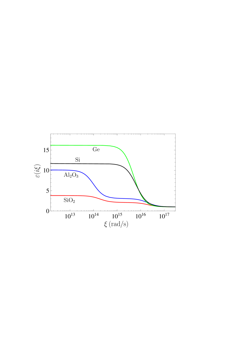
The Casimir free energy of SiO2 and Al2O3 films in vacuum is computed by (11), (12) and (8) over the wide range of thicknesses. For this purposes the dielectric permittivities of SiO2 and Al2O3 along the imaginary frequency axis presented in [65] have been used. They are shown by the two bottom lines in figure 1. Specifically, for SiO2 and Al2O3 we have and 10.1, respectively.
%
%
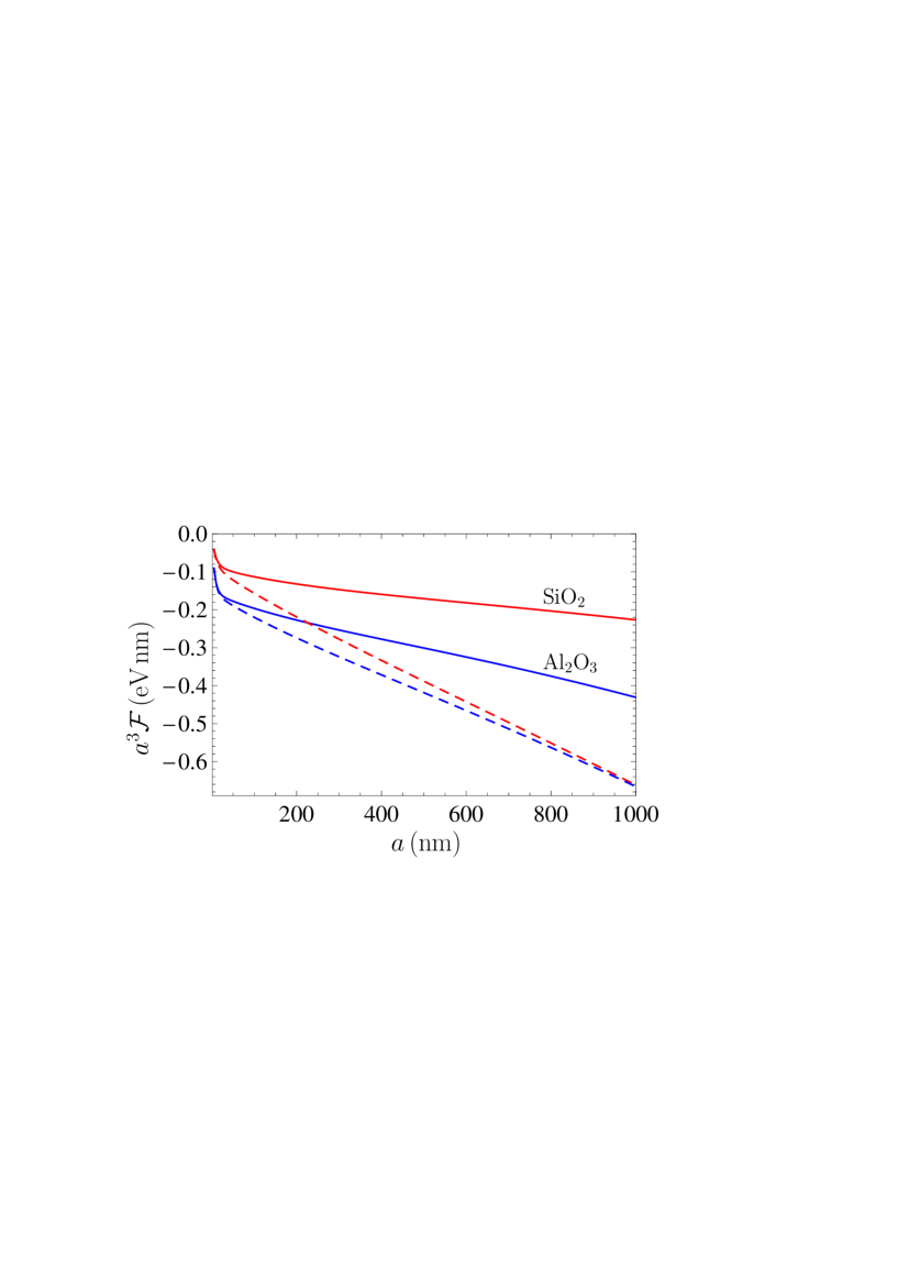
The computational results for the Casimir free energy per unit area of SiO2 and Al2O3 films multiplied by the third power of film thickness at K are shown in figure 2 by the top and bottom solid lines, respectively, in the region of from 5 to 1000 nm. As is seen in figure 2, the larger magnitudes of the negative Casimir free energy are obtained for a Al2O3 film which is characterized by the larger value of (see figure 1). According to our computational results, for a SiO2 film the magnitude of the zero-frequency term becomes approximately equal to the contribution of all nonzero Matsubara frequencies to the Casimir free energy for nm film thickness. The classical limit (18) is reached for m, where . This is in a very good agreement with the analytic result of Sec. II. For a free-standing Al2O3 film for nm and for m.
The computations of the Casimir free energy of a film have been repeated using the same equations, but with the dielectric permittivity (47) taking into account the dc conductivity of the film material. Note that the results of computations do not depend on specific values of the coefficient in (47), but only on the fact that it is not equal to zero. The computational results for are shown in figure 2 by the top and bottom dashed lines for SiO2 and Al2O3 films, respectively. As is seen in figure 2, the Casimir free energies computed using both approaches demonstrate considerable differences even for relatively thin films. Thus, for SiO2 films of , 100, 200, 500, and 1000 nm thicknesses the values of are greater than by the factors 1.22, 1.39, 1.66, 2.27, and 2.92, respectively. For Al2O3 films the quantity is equal to 1.07, 1.12, 1.20, 1.39, and 1.54 at the same respective thicknesses.
As can be seen from figure 2, the Casimir free energies computed for different materials with account of the dc conductivity go to one and the same classical limit (25) with increasing film thickness. For SiO2 and Al2O3 films the classical limit is reached for and m, respectively, i.e., for somewhat thinner films than in the case of neglected dc conductivity. The approximate equality holds for and 240 nm for SiO2 and Al2O3 films, respectively. In the classical limit, the magnitude of the Casimir free energy computred with included dc conductivity is substantially larger than that computed with neglected dc conductivity. Thus, and 1.61 for SiO2 and Al2O3 films, respectively.
4.2 Dielectric films deposited on metallic plate
Here, we compute the Casimir free energy of SiO2 and Al2O3 films deposited on a Au plate which can be considered as a semispace. The computations are performed by using (11)–(13) and (7). The dielectric permittivity of Au along the imaginary frequency axis is obtained from the tabulated optical data [61] extrapolated to lower frequencies by means of the Drude or plasma models using the standard procedures [2, 3, 29, 30, 31, 32, 33, 34, 35, 36]. In the configuration of a dielectric film deposited on a Au plate both extrapolations lead to almost coinciding results for the Casimir free energy of a film (up to 0.3%) because the TE reflection coefficient at the boundary surface between a dielectric film and vacuum vanishes at zero frequency.
%
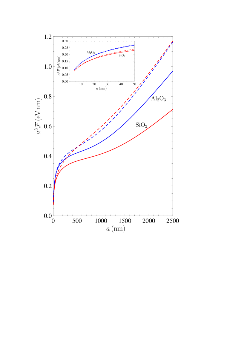
The Casimir free energy of SiO2 and Al2O3 films deposited on a Au plate was computed with neglected dc conductivity and multiplied by the third power of film thickness. The computational results are shown in figure 3 by the bottom and top solid lines, respectively, in the region from 5 to 2500 nm. Unlike the case of free-standing films, the Casimir free energy of films deposited on a Au plate is positive. The approximate equality holds for the film thicknesses nm (SiO2) and 550 nm (Al2O3). The classical limit is reached for m (SiO2 film) and m (Al2O3 film). In doing so it holds .
In the same figure the Casimir free energy of SiO2 and Al2O3 films computed with included dc conductivity is shown for the thinnest films by the lower and upper dashed lines, respectively. For film thicknesses nm the dashed lines change places and the one for SiO2 takes an upper position. For both SiO2 and Al2O3 films the approximate equation holds for nm. For and 2000 nm the ratio takes the values 1.25 and 1.62, respectively for SiO2 films, and 1.09 and 1.20, respectively, for Al2O3 films. In configurations with taken into account dc conductivity of film material, the classical limit is reached for m (SiO2) and m (Al2O3). In the inset in figure 3, the case of film thicknesses from 5 to 50 nm is shown in an enlarged scale for better visualization.
In the end of this section we note that the computational results for the Casimir free energy of dielectric films obtained with taken into account dc conductivity (the dashed lines in figures 2 and 3) are not realistic because this calculation approach is thermodynamically inconsistent (see section 3). Specifically, the intersection of the dashed lines in figure 3 is nonphysical. It is our opinion that the physically correct values of the Casimir free energy of dielectric films, both free-standing and deposited on metallic plate, are given by the solid lines in figures 2 and 3.
5 Control of the Casimir free energy of films deposited on a dielectric plate
In this section, we calculate the Casimir free energy of SiO2, Al2O3 and Ge films deposited on the plates made of high-resistivity Si. We investigate how the relationship between and depends on the thickness of a Si plate. It is shown that the values of the free energy and even its sign depend critically on the thickness of a dielectric substrate. We demonstrate also that one can control the Casimir free energy of a film by illuminating the plate with laser pulses.
5.1 Silica films
We have performed numerical computations of the Casimir free energy of SiO2 film of thickness deposited on the plate of finite thickness made of high-resistivity Si with . For this purpose (11) has been used where the reflection coefficients are given by (12) and (4). The latter equation was expressed in terms of the dimensionless variables with account of (14). We show that if the plate is made of dielectric material its thickness may have a profound effect on the Casimir free energy of a film.
The dielectric permittivity of SiO2 was already used above in computations of section 4. The dielectric permittivity of high-resistivity Si along the imaginary frequency axis is obtained by means of the Kramers-Kronig relation from the tabulated optical data Si [66]. It is shown in figure 1 as a function of frequency. In this section, we do not include the contribution of dc conductivity in the permittivities of dielectric materials because this inclusion leads to contradictions with thermodynamics (see section 3).
In figure 4 we present the computational results for the free energy per unit area of SiO2 film deposited on Si plate of finite thickness as a function of film thickness . These results are multiplied by the third power of the film thickness. The six lines counted from the figure bottom are plotted for the plates of , 2, 5, 10, 20, and m thickness. In so doing, it is assumed that , i.e., that the plate is thicker than a film. The top line in figure 4 demonstrates the computational results for the case of Si plate illuminated with laser pulses (see below).
%
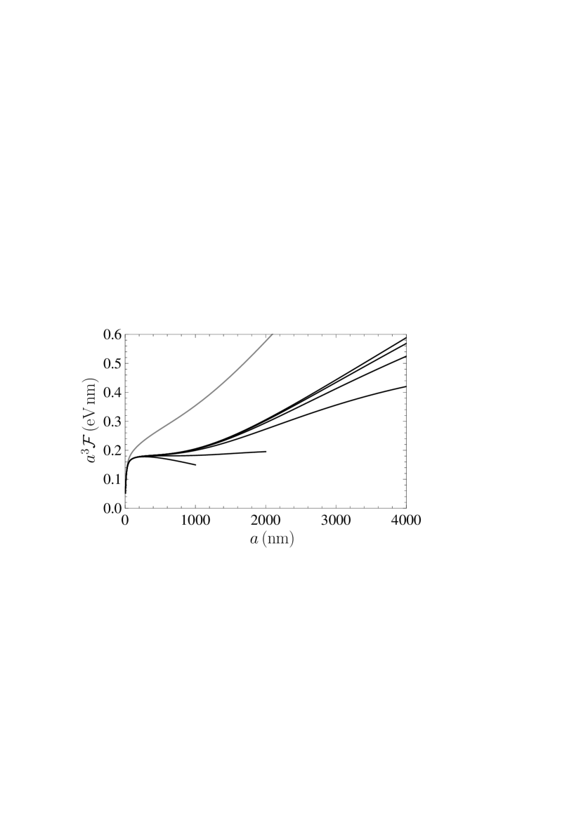
As is seen in figure 4, the Casimir free energy of SiO2 film is positive, but decreases with decreasing thickness of Si plate. This can be explained by the following. Computations show that the contribution of all nonzero Matsubara frequencies, , into the total Casimir free energy is almost independent on the thickness of a Si plate . Thus, for m changes for only 0.2% when increases from m to . One concludes that the dependence of on is mostly determined by the zero-frequency contribution . The latter depends on through the reflection coefficient defined in (4) and (14) as
| (51) |
Taking into account that the dominant contribution to the zero-frequency term of the free energy (11) is given by , one concludes that both the numerator and denominator in (51) are positive. For the fixed film thickness the relative role of the negative coefficient increases with decreasing and, as a result, the free energy decreases. In doing so, it remains positive, because, according to (17), another reflection coefficient in (11) is negative, .
It is instructive to compute the quantity defined as
| (53) |
which is in fact the function of the ratio . For SiO2 film deposited on a Si plate the computational results are shown by the top line in figure 5. As is seen in figure 5, the quantity is positive for all values of in accordance with the computational results presented in figure 4. Below we show that this quantity determines the qualitative behavior of the Casimir free energy of dielectric films deposited on a dielectric plate.
%

Now we show that it is possible to significantly increase the Casimir free energy of dielectric film deposited on a plate and make it independent on the plate thickness. For this purpose one can use the illumination by laser pulses from a 514 nm Ar laser incident on the bottom surface of the plate. Note that the effect of illumination was considered in the system Au-ethanol-Si [67]. Here, we consider the same parameters as in the experiment on optically modulated Casimir forces [2, 3, 41]. The high-resistivity Si was -doped with charge carrier density [66]. In the presence of pulse an equilibrium concentration of charge carriers (electrons and holes) of is rapidly established in the plate with some definite absorbed power [2, 3, 41]. Then, the dielectric permittivity of the plate is given by
| (54) |
Here, are the dimensionless plasma frequencies for electrons and holes, respectively, and the dimensional ones are equal to rad/s and rad/s [2, 3, 41]. In a similar way, the dimensionless and dimensional relaxation parameters are , rad/s and rad/s [68]. Note that in (54) notates the permittivity of Si in the metallic state, and not an inclusion of the dc conductivity in the dielectric state.
The Casimir free energy of SiO2 film in the presence of laser light on a Si plate was computed by (11), (12), (4), and (54), as a function of film thickness for different thicknesses of Si plate. Almost the same computational results are obtained if one puts in (54) , i.e., if the plasma model in place of the Drude model is used. The computational results are shown by the top line in figure 4. They are independent of the plate thickness. The classical limit is reached for film thicknesses nm.
5.2 Sapphire films
Now we show that the Casimir free energy of a dielectric film deposited on Si plate can be significantly different depending on the film material. For this purpose, we consider Al2O3 films covering a Si plate and perform numerical computations using the same (11), (12), and (4), as for SiO2 films.
The computational results for the Casimir free energy of Al2O3 film deposited on Si plate of 1, 2, 5, 10, 20, 50, and m thickness are multiplied by and shown in figure 6(a) by seven lines counted from the figure bottom, respectively, as a function of film thickness under a condition . Similar to the case of SiO2 films, the Casimir free energy of Al2O3 films for fixed decreases with decreasing thickness of a Si plate. However, unlike the case of SiO2 films, the Casimir free energy of Al2O3 films takes both positive and negative values. This is explained by the following.
%
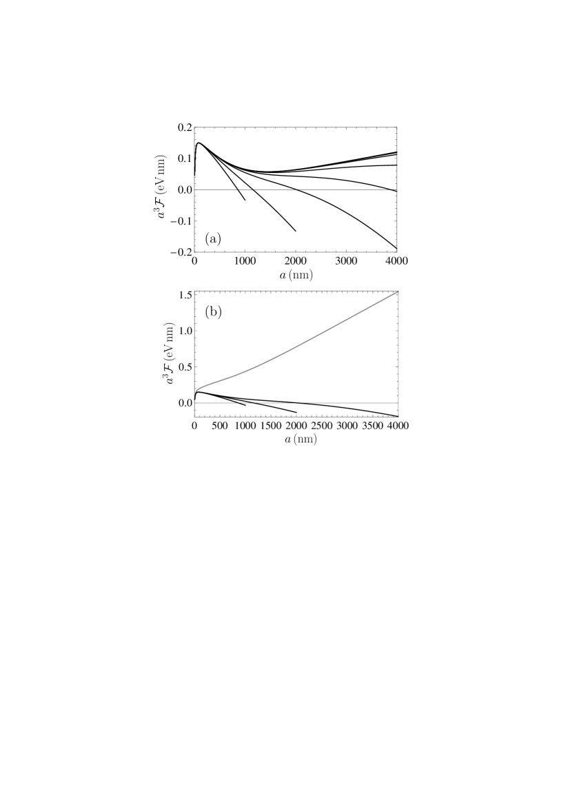
First we note that the dependence of on is again determined by the contribution of . For Al2O3 film of m thickness the contribution of to changes in the limits of 0.3% when varies from 1 m to . Then we take into account that the reflection coefficients in (51) are now equal to and . The smallness of results in the fact that even for the numerator in (51) is negative whereas the denominator is positive. Taking into account that for Al2O3 film , one obtains from Eq. (11) that the Casimir free energies of sufficiently thick films are negative. According to figure 6(a), the Casimir free energy of Al2O3 films of thicknesses equal to 855, 1150, 2050, and 3000 nm vanishes if these films are deposited on Si plates with thicknesses of 1, 2, 5, and 10 m, respectively. Thus, by matching the thicknesses of a film and a plate, one can control the sign and value of the Casimir free energy. The classical limit is again reached for film thicknesses exceeding 2500 nm.
Finally, we consider the effect of illumination of a Si plate with laser pulses. The same parameters as above and the dielectric permittivity (54) for Si in the presence of laser light have been used in computations. The computational results for the Casimir free energy of Al2O3 film deposited on illuminated Si plates of different thicknesses are shown in figure 6(b) by the top line as a function of film thickness. For comparison purposes, the same Casimir free energies, as in figure 6(a), are shown by the three lines counted from the figure bottom for the films deposited on Si plates of 1, 2, and 5 nm thickness, respectively, with no illumination. It is seen that in the presence of laser light the Casimir free energy of a film is positive for any film thickness and does not depend on the thickness of a plate.
5.3 Germanium films
Here, we consider the Casimir free energy of Ge films deposited on Si plates. The dielectric permittivity of Ge along the imaginary frequency axis is taken from [69]. It is shown by the top line in figure 1. The static dielectric permittivity of Ge is equal to .
The computational results for the Casimir free energy of Ge film deposited on Si plates of 1, 2, 5, 10, 20, and m thickness are multiplied by and shown in figure 7(a) by six lines counted from the figure bottom, respectively, as a function of film thickness under a condition . From figure 7(a) it is seen that the Casimir free energy of a film is negative and decreases with decreasing film thickness.
%
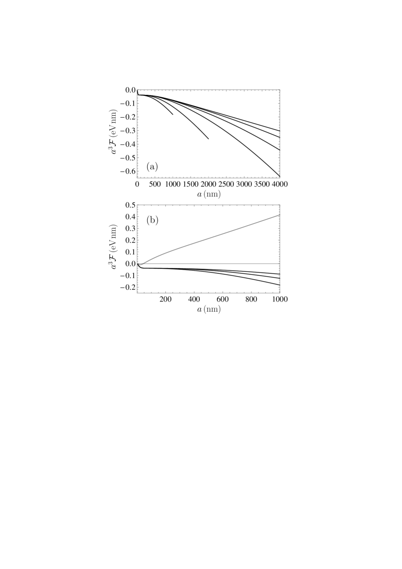
The dependence of the Casimir free energy on is again determined by the zero-temperature contribution . Computations show that decreases for 1% when the plate thickness increases from m to . For Ge the reflection coefficients in (51) are equal to and , i.e., are both negative. This leads to . Taking into account that for Ge , one finds that .
In the case of Ge films, illumination of a Si plate with laser light makes the strongest effect on the Casimir free energy. In this case the reflection coefficient on the boundary plane between Ge and Si changes not only its magnitude, but the sign as well by becoming positive in the presence of laser light. This leads to the change of a sign of the Casimir free energy.
In figure 7(b) the computational results for the Casimir free energy of Ge film multiplied by the third power of film thickness in the presence of laser light on a Si plate are shown by the top line as a function of film thickness. For comparison purposes, the Casimir free energies of Ge films deposited on nonilluminated Si plates of 1, 2, and 5 m thickness are plotted by the three lines counted from the figure bottom, respectively.
As is seen in figure 7(b), the Casimir free energy of the thinnest Ge films deposited on illuminated Si plates is negative. The values of the free energy do not depend on the thickness of a Si plate. For a film of 44 nm thickness, the Casimir free energy takes the zero value and for thicker films becomes positive. For Ge films deposited on the illuminated Si plate the classical limit is reached for the film thickness equal to 1600 nm.
6 Conclusions and discussion
In the foregoing, we have investigated the Casimir free energy of dielectric films, both free-standing in vacuum and deposited on material plates. It is shown that the Casimir free energy of free-standing films made of SiO2 and Al2O3 depends considerably on whether one neglects by the role of dc conductivity of film material or includes it in computations. The obtained differences in theoretical predictions are much larger than for the case of two parallel plates separated with a gap. In both theoretical approaches the classical limit is reached, but for thinner films, as compared to the gap width in the configuration of two parallel plates. If the dc conductivity is neglected, the classical limit depends on film material. With included dc conductivity, the classical limit demonstrates a universal behavior.
To find a convincing theoretical argument in favor of one or other calculation approach, we have investigated analytic behaviors of the Casimir free energy and entropy of a dielectric film at arbitrarily low temperature. It is shown that if the dc conductivity is neglected the Casimir entropy goes to zero with vanishing temperature in accordance to the third law of thermodynamics (the Nernst heat theorem). If the dc conductivity of film material is included in calculations, the Casimir entropy at zero temperature is shown to be equal to a positive quantity depending on the film parameters in violation of the Nernst heat theorem.
Similar situation takes place for two dielectric plates separated with a vacuum gap, where the inclusion of dc conductivity results in violation of the Nernst theorem [47, 48, 49, 50, 51]. In this respect one cannot overemphasize the fact that measurements of the Casimir interaction in dielectric systems are in good agreement with the thermodynamically consistent approach and exclude that one violating the Nernst theorem [41, 42, 43, 44, 45]. The problem of consistency with thermodynamics is interesting also for some configurations involving graphene and topological insulators which have been used to show the possibility of Casimir repulsion through a vacuum gap [70, 71, 72]. Using the formalism of the polarization tensor [73, 74, 75, 76], it was shown [77] that the Casimir entropy of graphene satisfies the Nernst heat theorem. Then, it is hardly surprising that measurements of the Casimir interaction in graphene system [78] were found in agreement with theoretical predictions exploiting the same formalism [79]. The validity of the Nernst theorem for the surface states of topological insulators is an open question to be solved in near future.
We have computed the Casimir free energy of SiO2 and Al2O3 films deposited on Au plates. It was shown that the computational results are almost independent on whether the Drude or the plasma model is used to describe the dielectric permittivity of Au at low frequencies. The obtained free energies are also independent on a thickness of Au plate provided it is larger than several tens nanometers. However, the Casimir free energy of dielectric films deposited on a Au plate are shown to be sensitive to an account or neglect of the dc conductivity of film material. According to our argumentation, the physically correct results are obtained within the calculation approach which ignores the dc conductivity of dielectric films.
Special attention was paid to the possibility of controlling the Casimir free energy of dielectric films made of different materials, such as SiO2, Al2O3 and Ge. For this purpose, dielectric films deposited on dielectric (high-resistivity Si) plates of finite thickness were considered. It is shown that for a fixed film thickness the Casimir free energy of a film decreases with increasing thickness of the plate. According to our results, the free energy of a film deposited on a Si plate can be positive (SiO2 films), positive, zero or negative depending on the film and plate thicknesses (Al2O3 films) and negative (Ge films). Illumination of the Si plate with laser light of Ar laser results in an independent of the plate thickness Casimir free energy of a film, which is mostly positive (with exception of only the case of very thin Ge films).
Taking into account a tendency for further miniaturization in various technologies, the above results may be useful in numerous applications of dielectric films in optics and microelectronics, where the fluctuation-induced forces are coming to play their role.
References
References
- [1] Parsegian V A 2005 Van der Waals forces: A Handbook for Biologists, Chemists, Engineers, and Physicists (Cambridge: Cambridge University Press)
- [2] Bordag M, Klimchitskaya G L, Mohideen U and Mostepanenko V M 2009 Advances in the Casimir Effect (Oxford: Oxford University Press)
- [3] Klimchitskaya G L, Mohideen U and Mostepanenko V M 2009 Rev. Mod. Phys. 81 1827
- [4] Rodriguez A W, Capasso F and Johnson S G 2011 Nature Photon. 5 211
- [5] French R H, Parsegian V A, Podgornik R, et al 2010 Rev. Mod. Phys. 82 1887
- [6] Woods L M, Dalvit D A R, Tkatchenko A, Rodrigues-Lopez P, Rodrigues A W and Podgornik R 2016 Rev. Mod. Phys. 88 045003
- [7] Caride A O, Klimchitskaya G L, Mostepanenko V M and Zanette S I 2005 Phys. Rev. A 71 042901
- [8] Buhmann S Y and Scheel S 2008 Phys. Rev. Lett. 100 253201
- [9] Safari H, Welsch D-G, Buhmann S Y and Scheel S 2008 Phys. Rev. A 78 062901
- [10] Chaichian M, Klimchitskaya G L, Mostepanenko V M and Tureanu A 2012 Phys. Rev. A 86 012515
- [11] Chan H B, Aksyuk V A, Kleiman R N, Bishop D J and Capasso F 2001 Science 291 1941
- [12] Esquivel-Sirvent R and Pérez-Pascual R 2013 Eur. Phys. J. B 86 467 (2013).
- [13] Zou J, Marcet Z, Rodriguez A W, Reid M T H, McCauley A P, Kravchenko I I, Lu T, Bao Y, Johnson S G and Chan H B 2013 Nature Commun. 4 1845
- [14] Sedighi M, Broer W H, Palasantzas G and Kooi B J 2013 Phys. Rev. B 88 165423
- [15] Chen F, Klimchitskaya G L, Mostepanenko V M and Mohideen U 2006 Phys. Rev. Lett. 97 170402
- [16] van Zwol P J, Palasantzas G and De Hosson J Th M 2008 Phys. Rev. B 77 075412
- [17] Gómez-Santos G 2009 Phys. Rev. B 80 245424
- [18] Bordag M, Klimchitskaya G L and Mostepanenko V M 2012 Phys. Rev. B 86 165429
- [19] Sernelius Bo E 2015 J. Phys.: Condens. Matter 27 214017
- [20] de Man S, Heeck K and Iannuzzi D 2010 Phys. Rev. A 82 062512
- [21] Bezerra V B, Klimchitskaya G L, Mostepanenko V M and Romero C 2010 Phys. Rev. D 81 055003
- [22] Klimchitskaya G L and Mostepanenko V M 2015 Eur. Phys. J. C 75 164
- [23] Bezerra V B, Klimchitskaya G L, Mostepanenko V M and Romero C 2016 Phys. Rev. D 94 035011
- [24] Lifshitz E M 1955 Zh. Eksp. Teor. Fiz. 29 94 (1956 Sov. Phys. JETP 2 73)
- [25] Adamson A W and Gast A P 1997 Physical Chemistry of Surfaces (New York: Wiley)
- [26] Klimchitskaya G L and Mostepanenko V M 2015 Phys. Rev. A 92 042109
- [27] Klimchitskaya G L and Mostepanenko V M 2016 Phys. Rev. A 93 042508
- [28] Klimchitskaya G L and Mostepanenko V M 2016 Phys. Rev. B 94 045404
- [29] Decca R S, Fischbach E, Klimchitskaya G L, Krause D E, López D and Mostepanenko V M 2003 Phys. Rev D 68 116003
- [30] Decca R S, López D, Fischbach E, Klimchitskaya G L, Krause D E and Mostepanenko V M 2005 Ann. Phys. NY 318 37
- [31] Decca R S, López D, Fischbach E, Klimchitskaya G L, Krause D E and Mostepanenko V M 2007 Phys. Rev D 75 077101
- [32] Decca R S, López D, Fischbach E, Klimchitskaya G L, Krause D E and Mostepanenko V M 2007 Eur. Phys. J. C 51 963
- [33] Chang C-C, Banishev A A, Castillo-Garza R, Klimchitskaya G L, Mostepanenko V M and Mohideen U 2012 Phys. Rev. B 85 165443
- [34] Banishev A A, Klimchitskaya G L, Mostepanenko V M and Mohideen U 2013 Phys. Rev. Lett. 110 137401
- [35] Banishev A A, Klimchitskaya G L, Mostepanenko V M and Mohideen U 2013 Phys. Rev. B 88 155410
- [36] Bimonte G, López D and Decca R S 2016 Phys. Rev. B 93 184434
- [37] Mostepanenko V M 2015 J. Phys.: Condens. Matter 27 214013
- [38] Bimonte G 2014 Phys. Rev. Lett. 112 240401
- [39] Bimonte G 2014 Phys. Rev. Lett. 113 240405
- [40] Bimonte G 2015 Phys. Rev. B 91 205443
- [41] Chen F, Klimchitskaya G L, Mostepanenko V M and Mohideen U 2007 Phys. Rev. B 76 035338
- [42] Obrecht J M, Wild R J, Antezza M, Pitaevskii L P, Stringari S and Cornell E A 2007 Phys. Rev. Lett. 98 063201
- [43] Chang C-C, Banishev A A, Klimchitskaya G L, Mostepanenko V M and Mohideen U 2011 Phys. Rev. Lett. 107 090403
- [44] Banishev A A, Chang C-C, Castillo-Garza R, Klimchitskaya G L, Mostepanenko V M and Mohideen U 2012 Phys. Rev. B 85 045436
- [45] Klimchitskaya G L and Mostepanenko V M 2008 J. Phys. A: Math. Theor. 41 312002
- [46] Klimchitskaya G L, Mohideen U and Mostepanenko V M 2012 J. Phys.: Condens. Matter 24 424202
- [47] Geyer B, Klimchitskaya G L and Mostepanenko V M 2005 Phys. Rev. D 72 085009
- [48] Klimchitskaya G L, Geyer B and Mostepanenko V M 2006 J. Phys. A: Math. Gen. 39 6495
- [49] Klimchitskaya G L, Mohideen U and Mostepanenko V M 2008 J. Phys. A: Math. Theor. 41 432001
- [50] Geyer B, Klimchitskaya G L and Mostepanenko V M 2008 Ann. Phys. NY 323 291
- [51] Klimchitskaya G L and Korikov C C 2015 J. Phys.: Condens. Matter 27 214007
- [52] Landau L D and Lifshitz E M 1980 Statistical Physics, part I (Oxford: Pergamon Press)
- [53] Rumer Yu B and Ryvkin M Sh 1980 Thermodynamics, Statistical Physics, and Kinetics (Moscow: Mir)
- [54] Bezerra V B, Klimchitskaya G L and Mostepanenko V M 2002 Phys. Rev. A 65 052113
- [55] Bezerra V B, Klimchitskaya G L and Mostepanenko V M 2002 Phys. Rev. A 66 062112
- [56] Bezerra V B, Klimchitskaya G L, Mostepanenko V M and Romero C 2004 Phys. Rev. A 69 022119
- [57] Bordag M and Pirozhenko I 2010 Phys. Rev. D 82, 125016
- [58] Klimchitskaya G L and Korikov C C 2015 Phys. Rev. A 91 032119
- [59] Boström M and Sernelius Bo E 2004 Physica A 339 53
- [60] Baklanov M, Maex K and Green M (eds) 2007 Dielectric Films for Advanced Microelectronics (Chichester: Wiley)
- [61] Palik E D (ed) 1985 Handbook of Optical Constants of Solids, vol 1 (New York: Academic)
- [62] Klimchitskaya G L and Geyer B 2008 J. Phys. A: Math. Theor. 41 164032
- [63] Shackelford J F and Alexander W 2001 (eds) Materials Science and Engineering Handbook (Boca Raton: CRC Press)
- [64] Klimchitskaya G L and Mostepanenko V M 2017 Phys. Rev. A 95 012130
- [65] Bergström L 1997 Adv. Colloid Interface Sci. 70 125
- [66] Palik E D (ed) 1991 Handbook of Optical Constants of Solids, vol 2 (New York: Academic)
- [67] Klimchitskaya G L, Mohideen U and Mostepanenko V M 2007 J. Phys. A: Math. Theor. 40 841
- [68] Vogel T, Dodel G, Holzhauer E, Salzmann H and Theurer A 1992 Appl. Opt. 31 329
- [69] http://www.ioffe.ru/SVA/NSM
- [70] Grushin A G and Cortijo A 2011 Phys. Rev. Lett. 106 020403
- [71] Martinez J C and Jalil M B A 2013 J. Appl. Phys. 113 204302
- [72] Martinez J C and Jalil M B A 2015 J. Opt. Soc. Am. B 32 157
- [73] Bordag M, Fialkovsky I V, Gitman D M and Vassilevich D V 2009 Phys. Rev. B 80 245406
- [74] Fialkovsky I V, Marachevsky V N and Vassilevich D V 2011 Phys. Rev. B 84 035446
- [75] Bordag M, Klimchitskaya G L, Mostepanenko V M and Petrov V M 2015 Phys. Rev. D 91 045037
- [76] Bordag M, Klimchitskaya G L, Mostepanenko V M and Petrov V M 2016 Phys. Rev. D 93 089907(E)
- [77] Bezerra V B, Klimchitskaya G L, Mostepanenko V M and Romero C 2016 Phys. Rev. A 94 042501
- [78] Banishev A A, Wen H, Xu J, Kawakami R K, Klimchitskaya G L, Mostepanenko V M and Mohideen U 2013 Phys. Rev. B 87 205433
- [79] Klimchitskaya G L, Mohideen U and Mostepanenko V M 2014 Phys. Rev. B 89 115419