Space charge compensation for intense ions beams in booster synchrotrons
Abstract
For booster synchrotrons, like the SIS at GSI, space charge is one of the main intensity limitations. At injection energy the space charge induced tune spreads in booster synchrotrons are large, reaching up to 0.5 and the ramping times are typically short. We study the effect of several localized electron lenses distributed equally around the circumference in order to compensate for the transverse space charge force.
pacs:
29.27.Bd, 29.20.LqI Introduction
Space charge represents a major intensity limitation in booster synchrotrons operating at low or medium energies. The limitation arises due to stopbands caused by envelope instabilities driven by the lattice structure Baartman (1998); Hofmann and Boine-Frankenheim (2017) or due to the space charge induced tune spread and its overlap with incoherent, nonlinear resonances Franchetti et al. (2010). Depending on the chosen working point and the intensity, coherent or incoherent effects can dominate or occur together. The space charge limit in booster synchrotrons is still an active field of research, both numerically as well as experimentally. After the success of electron lenses for beam-beam compensation in RHIC Gu et al. (2017), the potential of such lenses to also compensate, at least partially, for space charge would increase the potential for higher intensities in booster synchrotrons. However, one should keep in mind that space charge acts as a distributed defocusing error, whereas the beam-beam tune shift has a local source. Therefore localized lenses cannot be expected to be as efficient for space charge as they are for beam-beam compensation. One has to install several lenses around the ring instead of placing one lens close to the beam-beam interaction section. Furthermore, in order to be effective for space charge, the electron current profile has to match the bunch profiles of the ions. For very short, relativistic bunches the optimum bunch overlap was studied in Litvinenko and Wang (2014). For booster synchrotrons with typically long bunches compared to the length of an electron lens, the matching of the electron current profile with the ion bunch profile might be easier to achieve in experiments. Different concepts for space charge compensation were studied in Aiba et al. (2007). Electron lenses for space charge compensation were also discussed in Shiltsev (2016). The possibility of space charge compensation in booster synchrotrons was studied in Burov, Foster, and Shiltsev (2000) using analytical models for the envelope instability and the coherent dipole tune. The limitation of the compensation degree by the upward shift of the coherent dipole tune was pointed out. For the FNAL booster synchrotron a minimum number of lenses was estimated. For the SIS synchrotron, used as a reference machine in this study, the incoherent resonances induced by the space charge field of the electron beam in the cooling section were analyzed in Sorge, Boine-Frankenheim, and Franchetti (2007). For electron cooling the tune shift induced by the electron beam is usually well below 0.1 and the ion beam currents are low. Therefore incoherent resonances dominate and were identified up to order 6 in the tracking studies together with a severe emittance growth. The present study relies on a simulation model for intense beams including the linear synchrotron lattice, the 2D self-consistent space charge force and simple kicks for the lenses. We compare the results of extended simulation scans to analytical models.
II Space charge compensation: 2D model
The compensation of space charge in bunches is a 3D problem. The transverse profile of the electron beams and its current profile both have to match the transverse profile and the longitudinal bunch profile of the circulating ion bunches. In this study we assume ion bunches that are long compared to the interaction length with the electron beam. The current profile of the the electron beam in the interaction section is assumed to follow exactly the ion bunch profile. If a certain space charge compensation degree is chosen for the bunch center, it will therefore hold also at the bunch ends. If we further assume that the relevant effects are faster than the synchrotron oscillation period, a 2D model for the bunch center slice is sufficient. The space charge tune shift in the bunch center is (vertical plane)
| (1) |
where and are the relativistic parameters for the ion beam, is the total particle number in the ring, the charge state of the ions, the mass number, is the bunching factor, is the unnormalized emittance of the equivalent KV beam.
The beam-beam tune shift (co-propagating: , counter-propagating: ) induced by one electron lens is
| (2) |
Hereby we assume that the transverse profiles of both beams overlap ideally. is the current of the electron beam, is the length of the interaction section, is the velocity of the electrons divided by the speed of light. The required electron current in order to fully compensate a given space charge tune shift with one lens is
| (3) |
The degree of space charge compensation we define as
| (4) |
where is the space charge tune shift and the total beam-beam tune shift generated by electron lenses. The GSI SIS heavy-ion synchrotron Appel, Boine-Frankenheim, and Petrov (2017) is used as a reference case for the study (see also Appendix A). The SIS has a circumference of m and periodic sectors. The injection energy is 11.4 MeV/u. Example beam parameters are given in Table 1. The parameters of the existing SIS electron cooler are given in Table 2.
| Ion | Ar18+ |
|---|---|
| 11.4 MeV/u | |
| 2 | |
| 0.3 | |
| 150/50 mm mrad | |
| - | 0.2/0.5 |
| 4.14/3.6 |
| Max. electron energy | 35 keV |
|---|---|
| Max. current | 2 A |
| effective length | 2.8 m |
| 8/15 m |
As a simple example, if we use the SIS cooler in the conventional way (co-propagating, ) and assume a symmetric Ar18+ beam with mmrad a tune shift of could be compensated (see also Sorge, Boine-Frankenheim, and Franchetti (2007)). This of course requires an ideal overlap of both beams. The compensation of the reference beam parameters given in Table 1 would require at least an electron current of 2 A and .
III Stability considerations: Orbit and Optical functions
The transverse space charge force acts as a distributed (de)focusing error around the ring. In periodic focusing lattices space charge alone only leads to incoherent structural or coherent parametric resonances. On the contrary the electron lenses act as localized focusing errors. If they are spaced symmetrically around the synchrotron they define new periodic structure cells (for ). The lenses also result in additional nonlinear error resonances.
Before discussing discreteness effects, the limitation of the compensation degree due to the shift of the coherent tune is discussed. This limitation has been pointed out in Burov, Foster, and Shiltsev (2000). The focusing electron lenses cause an upward shift of the coherent tune (the frequency of the beam centroid oscillations)
| (5) |
where is the coherent tune and the bare tune. This has been experimentally shown at the SIS for both coasting and bunched beams in Stem and Boine-Frankenheim (2016). An important limitation for the total strength of the lenses is that should stay well below integers , in order for the closed orbit to remain stable. This limitation only depends on the total beam-beam tune shift and not on the number of lenses.
The number of lenses is important for the perturbation of the optical functions. The beating of the -function caused by an electron lens , treated here as a localized focusing error is (see e.g.Lee (1999))
| (6) |
Assuming that the lenses are located symmetrically around the ring, is the phase advance from the beginning of the section to the position of the lens and the phase advance at the observation point. The maximum beta beating caused by the lenses is approximately
| (7) |
where is the total beam-beam tune shift. If we require that the maximum beta beating remains well below 1, only very small space charge tune shifts can be compensated with one lens (well below 0.1 in the SIS). For the typical space charge tune shifts in high current synchrotrons, of the order of , several (at least for the SIS) lenses are required to at least partially compensate the space charge tune shift, without causing a large beating amplitude of the optical functions (see also Appendix A for more detailed results).
It is important to notice that for dc electron beams the beta beating could be reduced by corrector quadrupoles. However, for the desired pulsed electron beam operation, a correction with fixed gradient quadrupoles is not possible.
The required number of lenses can also be estimated from the stability criteria for betatron oscillations in periodic focusing lattices:
| (8) |
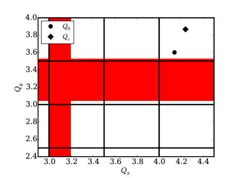
where the tune is the particle tune and is the total beam-beam tune shift induced by the electron lenses. The area in tune space with are stopbands in which the amplitude of linear betatron oscillations grows exponentially. Including the space charge tune shift in the particle tune causes a shift of the stopbands, but leaves the stopband width unchanged. The stopband width is determined by the beam-beam tune shift and the density of bands by . An example case for the SIS with lenses, an assumed enlarged space charge tune shift of () and a compensation degree is shown in Figure 1. The distance between stopbands is , which is also why we call those stopbands ””. The stopband width increases as . Figure 1 indicates that for a total beam-beam tune shift of might be feasible. The degree of compensation is limited by the coherent tune approaching the integer value . How close is allowed to approach the integer resonance depends also on the accuracy of the alignment of the electron lenses and the circulating ion beam. The tolerance for such offsets and the resulting localized dipole kicks are not part of this study.
IV Envelope perturbations and instabilities with electron lenses
The 2D envelope equations (see for example Yuan et al. (2017)) can be solved numerically including the electron lenses, treated as thin, linear defocusing elements. Thereby one can obtain space charge structural instabilities and their modification due to the lenses. Furthermore, for stable beams, this self-consistent model can predict the perturbation of the optical functions and, for unstable beams, the stopbands with localized lenses and linear space charge.
First, we use simple analytical expressions to discuss the expected modifications and shifts of space charge structural resonances due to the electron lenses. The condition for a parametric resonance or envelope instability including a partial incoherent space charge compensation is
| (9) |
where is the bare tune, is the coherent tune shift for the envelope modes, is the harmonic number and is the number of structure cells, which equals the number of electron lenses in our scenario. It is important to note that the stopbands arising from (coherent) envelope instabilities, also called stopbands, are different from the stopbands shown in section III.
Both stopbands can overlap, as it will be the case in the SIS close to . In this case the stopband dominates, as it defines the linear stability for the single particle and envelope betatron oscillations.
The coherent tune shifts in Equation 9 can be estimated in and assuming uncoupled envelope oscillations Boine-Frankenheim, Hofmann, and Struckmeier (2016)
| (10) |
With and the beam radii in and for vanishing space charge, the ellipticity parameter is given for equal emittances as .
The coherent tune shift is smaller (factor 5/8 for a symmetric beam) than the incoherent tune shift . This effect is often called ”coherent advantage”: With increasing space charge the coherent envelope tune will hit the resonance after the incoherent particle tune. For strong space charge, like in booster rings, the relevant resonance is assumed to be the coherent and not the incoherent one Hofmann and Boine-Frankenheim (2017).
The stopbands corresponding to the envelope instability are shifted downwards by the presence of the electron lenses. Because of the ”coherent advantage” the compensation can be partial , with for symmetric beams.
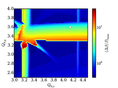
Next we solve the time-dependent 2D envelope equations numerically and plot the results for the maximum beta function mismatch amplitude as a function of the bare tunes. The result of such tune scans are shown in Figure 2. For the scan initial tune shifts , which are higher than the SIS reference parameters. The scan shown on upper plot is performed without electron lenses. The shift of the lower edge of the two stopbands (in and ) is well described by Equation 9 with and . The white dot indicates the reference high-current working point in the SIS, which lies inside the unstable area for the chosen beam intensity. Very weakly visible are the parametric sum resonance (the diagonal line) Boine-Frankenheim, Hofmann, and Struckmeier (2016) and the dispersion induced envelope resonance (the vertical line at ) Yuan et al. (2017).
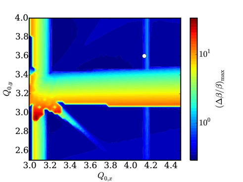
The lower part of Figure 2 shows a tune scan performed with electron lenses (one in each SIS lattice period). The lenses are adjusted to provide a partial compensation of the space charge tune shift by one-third (), limited by the integer resonance. The stopband’s lower edge, which is again well described by Equation 9, remains close to . The width of the stopbands remains unaffected by the presence of the lenses. The effect of the lenses is basically only to shift the stopbands downwards.
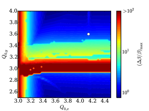
If we reduce the number of lenses to six (and so also the periodicity of the ring), keeping the compensation at , the resulting scan is shown in Figure 3. The stopband close to now broadens and resembles the stopband shown in Figure 1. Furthermore the stable beam (blue areas) shows strong beta beating. For (not shown) the situation worsens and stable areas with tolerable beta beating are difficult to identify.
V Particle-In-Cell (PIC) tracking: incoherent and coherent resonances with electron lenses
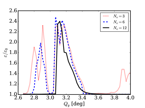
The 2D envelope model, discussed in the previous section, allows very fast tune scans and helps to separate coherent and incoherent effects, which occur together in Particle-In-Cell (PIC) tracking simulations. In our simplified model incoherent resonances are excited by the (static) nonlinear beam-beam forces and by the harmonic of the nonlinear space charge force. We use an initial waterbag distribution for the PIC macro-particles, which might be closer to the actual distribution of the injected beam in a booster synchrotron than a Gaussian. A tune scan along a vertical line through the reference SIS working point performed with the PIC simulation code pyPATRIC is shown in Figure 4. The beam and compensation parameters are the same as the ones used in the previous section. The emittance growth observed after cells is shown for lenses. For the envelope stopband with its peak close to is present also in the PIC simulations. For and between and , in agreement with the stability condition Equation 8, the broader stopband appears together with presumably fourth order resonances below and induced by the nonlinear lenses.
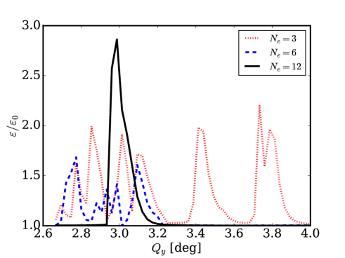
For the less intense SIS reference beam Table 1 the compensation, limited by the integer resonance, can be larger . The beam-beam tune shift in this case is still similar to the more intense beam case. The result of the scan for the reference beam is shown in Figure 5. For the envelope stopband is now close to . For and the stopband appears between and . For two presumably fourth order resonance lines appear above the stopband.
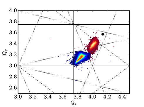
An example resonance diagram (dashed fourth order lines) and tune footprint for is shown in Figure 6 for and (red). For comparison, the tune footprint for the uncompensated beam is shown as well (red/blue).
It is important to note that in our 2D PIC model we use electron lenses that are ideally matched to the ion beam. In more realistic scenarios the electron beam would be kept strictly round, because the beam is guided by a solenoid field and affected by the rotation (see also Appendix A). We found that for round electrons beams different nonlinear resonances are excited, compared to the fully elliptical beams used in this model.
VI Conclusions and Outlook
Within a simplified 2D beam dynamics model we studied the (partial) compensation of large space charge tune shifts, typical for booster synchrotrons, by localized electron lenses. The model includes self-consistent 2D space charge and fixed (nonlinear) kicks from the localized electron lenses. We use the GSI SIS18 heavy-ion synchrotron as reference case and only account for transverse space charge and the lenses as the only ’error’ sources in our simulation model. From the envelope model we obtain the beta beating amplitudes, the stopbands (caused by the localized gradient errors) as well as the envelope instability or stopbands (caused by space charge structural instabilities). The PIC simulation provides additional information on nonlinear resonances excited by the lenses, which cannot be resolved in the envelope model.
The degree of space charge compensation is limited by the integer resonance and orbit stability. This limitation has been assumed here in order to adjust the compensation degree.
If the number of lenses equals the lattice periodicity (), we find that the lenses shift the stopbands downwards, without affecting their width. In this case the stopband are not relevant, as the phase advance per cell is usually chosen well below . For the localized lenses reduce the symmetry of the lattice and cause severe beta beating as well as stopbands, spaced every in tune space. Their width corresponds to the total beam-beam tune shift induced by the lenses and their center position is shifted by space charge. The stopband usually overlaps and substitutes a stopband. Furthermore, incoherent nonlinear error resonances induced by the lenses are clearly visible in the PIC simulation scans.
In conclusion, for the large space charge tune shifts typical for booster synchrotrons a partial compensation by might be possible, provided that there are sufficiently many lenses. For the SIS we estimate a minimum amount of in order to have a reasonable chance to find a working point range that allows for partial compensation, outside of any stopbands and nonlinear resonances induced by the lenses and with tolerable beta beating. For any the unwanted effects caused by the lenses seem to dominate in our example study. One has to keep in mind that in our model many additional sources of errors are not included, for example systematic and random errors in the alignment of the lenses and in the 3D overlap between the ion and electron beams. The alignment errors of the lenses will add to the closed orbit instability at integer coherent tunes. The errors in the electron current for different lenses will lead to additional gradient errors stopbands. Also we did not include any lattice errors, which are usually the reason for the space charge limit without the lenses. Therefore we expect our model to be very optimistic.
Still there is room for further studies and possible improvements. For example, instead of trying to ideally overlap both beams one could use a transverse McMillan lens profile Stancari et al. (2015). This could reduce the effect of nonlinear resonances induced by the lenses, but would not affect the error stopbands or the beta beating. The compensation might work better for lower space charge tune shifts ( or lower) and a space charge limit dominated by nonlinear lattice errors. This would require studies with a 3D simulation model including synchrotron motion over much longer time scales than in this study. We plan to conduct such long-term simulation studies for the FAIR SIS100 synchrotron, first within a frozen 3D space charge model.
Appendix A Perturbation of the optical functions in the SIS
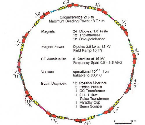
We assume that all electron lenses in the SIS will be located at the same position as the existing electron cooler in section 10 (see Figure 7).
The optical functions including space charge and the thin electron lens for one SIS cell obtained within our envelope model (not all lattice elements are included) are shown in Figure 8 for and in Figure 9 for .
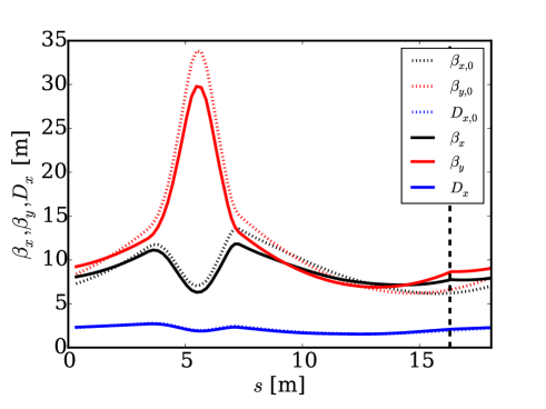
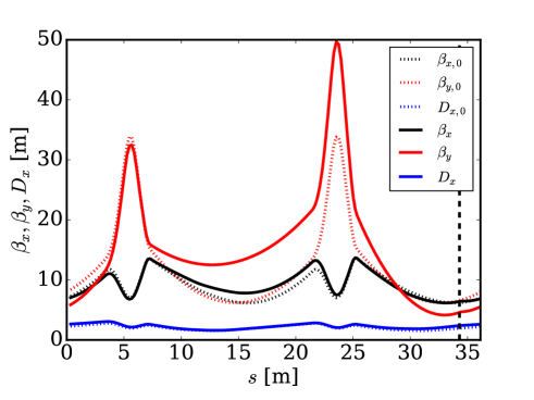
It is important to note that the ion beam at the location of the lenses will in general not be round. Even with equal functions in the asymmetric emittances will lead to an elliptical beam profile at the location of the lens. The beating can further enhance the difference in the functions. The electron beam guided by a solenoid field and affected by the rotation, on the other hand, is usually round. This further complicates the matching of the transverse profiles of both beams. In our simplified model we treat both beams as ideally matched. Furthermore the phase advance along the interaction sections is finite, whereas we use a thin lens approximation.
References
- Baartman (1998) R. Baartman, AIP Conference Proceedings 448, 56 (1998).
- Hofmann and Boine-Frankenheim (2017) I. Hofmann and O. Boine-Frankenheim, Physical Review Accelerators and Beams 20, 014202 (2017).
- Franchetti et al. (2010) G. Franchetti, O. Chorniy, I. Hofmann, W. Bayer, F. Becker, P. Forck, T. Giacomini, M. Kirk, T. Mohite, C. Omet, a. Parfenova, and P. Schütt, Physical Review Special Topics - Accelerators and Beams 13, 114203 (2010).
- Gu et al. (2017) X. Gu, W. Fischer, Z. Altinbas, M. Anerella, E. Bajon, M. Bannon, D. Bruno, M. Costanzo, A. Drees, D. Gassner, R. Gupta, J. Hock, M. Harvey, A. Jain, J. Jamilkowski, P. Kankiya, R. Lambiase, C. Liu, Y. Luo, M. Mapes, A. Marusic, C. Mi, R. Michnoff, T. Miller, M. Minty, S. Nemesure, W. Ng, D. Phillips, A. Pikin, P. Rosas, G. Robert-Demolaize, T. Samms, J. Sandberg, V. Schoefer, T. Shrey, Y. Tan, R. Than, C. Theisen, P. Thieberger, J. Tuozzolo, P. Wanderer, W. Zhang, and S. White, Physical Review Accelerators and Beams 20, 023501 (2017).
- Litvinenko and Wang (2014) V. N. Litvinenko and G. Wang, Physical Review Special Topics - Accelerators and Beams 17, 114401 (2014).
- Aiba et al. (2007) M. Aiba, M. Chanel, U. Dorda, R. Garoby, J.-P. Koutchouk, M. Martini, E. Metral, Y. Papaphilippou, W. Scandale, F. Zimmermann, V. Shiltsev, and G. Franchetti, 2007 IEEE Particle Accelerator Conference (PAC) , 3390 (2007).
- Shiltsev (2016) V. D. Shiltsev, Electron Lenses for Super-Colliders, Particle Acceleration and Detection (Springer New York, New York, NY, 2016) pp. 163–181.
- Burov, Foster, and Shiltsev (2000) A. V. Burov, G. W. Foster, and V. D. Shiltsev, , 1 (2000).
- Sorge, Boine-Frankenheim, and Franchetti (2007) S. Sorge, O. Boine-Frankenheim, and G. Franchetti, in Proc. of COOL 2007 (2007) pp. 121–124.
- Appel, Boine-Frankenheim, and Petrov (2017) S. Appel, O. Boine-Frankenheim, and F. Petrov, Nuclear Instruments and Methods in Physics Research Section A: Accelerators, Spectrometers, Detectors and Associated Equipment 852, 73 (2017).
- Stem and Boine-Frankenheim (2016) W. D. Stem and O. Boine-Frankenheim, in ICFA-HB 2016 (2016) pp. 496–498.
- Lee (1999) S.-Y. Lee, Accelerator physics (World scientific Singapore, 1999).
- Yuan et al. (2017) Y. S. Yuan, O. Boine-Frankenheim, G. Franchetti, and I. Hofmann, Physical Review Letters 118, 154801 (2017).
- Boine-Frankenheim, Hofmann, and Struckmeier (2016) O. Boine-Frankenheim, I. Hofmann, and J. Struckmeier, Physics of Plasmas 23, 090705 (2016).
- Stancari et al. (2015) G. Stancari, A. Burov, V. Lebedev, S. Nagaitsev, E. Prebys, and A. Valishev, , 0 (2015), arXiv:1511.01812 .