Nucleated dewetting in supported ultra-thin liquid films with hydrodynamic slip
Abstract
This study reveals the influence of the surface energy and solid/liquid boundary condition on the breakup mechanism of dewetting ultra-thin polymer films. Using silane self-assembled monolayers, SiO2 substrates are rendered hydrophobic and provide a strong slip rather than a no-slip solid/liquid boundary condition. On undergoing these changes, the thin-film breakup morphology changes dramatically – from a spinodal mechanism to a breakup which is governed by nucleation and growth. The experiments reveal a dependence of the hole density on film thickness and temperature. The combination of lowered surface energy and hydrodynamic slip brings the studied system closer to the conditions encountered in bursting unsupported films. As for unsupported polymer films, a critical nucleus size is inferred from a free energy model. This critical nucleus size is supported by the film breakup observed in the experiments using high speed in situ atomic force microscopy.
From the simplest solid, liquid and vapor phases, to exotic condensed matter systems, equilibrium phases and phase transitions, along with their dynamics, make up an essential part of the fundamental description of many systems Baus and Tejero (2008); Chaikin and Lubensky (1995). This statement is also valid for nanometric liquid films on solid substrates. Thin films can be described through an effective interface potential Israelachvili and Tabor (1972); Seemann et al. (2001, 2005); Thiele et al. (2001); Thiele (2003); Blossey (2012); Dietrich et al. (2013), , in which is the energy per unit area, and is the local film height. The free energy is then a functional Thiele et al. (2001); Thiele (2003); Blossey (2012); Dietrich et al. (2013), , of the film height distribution. Depending on the effective interface potential, a flat film with everywhere, may be in stable equilibrium or susceptible to breakup Oron et al. (1997); Reiter (1992); Jacobs et al. (1998); de Gennes et al. (2003). When, as considered in this work, it is energetically preferred for the liquid to phase separate into regions of differing film thickness, the morphology of the phase separated regions gives crucial information on the breakup mechanism.
Two dewetting mechanisms can be observed in experiments on SiO2 substrates. One is nucleated dewetting Reiter (1992); Jacobs et al. (1998), which can be subdivided into heterogeneous and homogeneous (or thermal) nucleation. For heterogeneous nucleation, an external stimulus like a local topographical defect or chemical heterogeneity leads to the breakup; thermal nucleation in supported polymer films has only rarely been observed Seemann et al. (2001, 2005). The second mechanism, which occurs spontaneously, is called spinodal dewetting Vrij (1966); Seemann et al. (2001); Becker et al. (2003); Wang and Tsui (2006). In a spinodally dewetting film, capillary waves at the liquid/air interface are amplified by van der Waals (vdW) interactions between the air/liquid interface and the liquid/substrate interface. When the amplitude of the fastest growing capillary wave reaches the film thickness, holes are created in the film. The dominant rupture mechanism depends on various experimental parameters Seemann et al. (2005); namely, the thickness of the liquid film and the substrate properties, including the surface energy and vdW interactions between film/air interface and the full depth profile of the substrate Seemann et al. (2001, 2005); Israelachvili (2011). A polystyrene (PS) film on a pure Si substrate is stable, for example. If a SiO2 layer is added, the film becomes unstable to nucleated dewetting or spinodal rupture Seemann et al. (2001, 2005).
Removing the substrate entirely, thereby creating an unsupported film, another system that is unstable to rupture can be studied Debrégas et al. (1995); Dalnoki-Veress et al. (1999); Roth and Dutcher (2006); Croll and Dalnoki-Veress (2010); Rathfon et al. (2011). As with certain supported films, the interfaces on either side of an unsupported film are attractive Israelachvili (2011). These unsupported films are thus in principle susceptible to spontaneous rupture, but are observed to rupture via nucleation only. The nucleated breakup of freestanding films can occur through a defect as was studied by Debregeas and coworkers Debrégas et al. (1995) and others Dalnoki-Veress et al. (1999); Roth and Dutcher (2006), or may occur via a random nucleation event Croll and Dalnoki-Veress (2010); Rathfon et al. (2011). In the random nucleation case, fluctuations of the liquid film lead to the formation of holes. In contrast to spinodal dewetting, vdW interactions are not the dominant driving force for this process. The liquid film can instead be treated as an energy barrier: bending the surface introduces excess area and results in an energetic cost that may be overcome by random thermal fluctuations Croll and Dalnoki-Veress (2010).
Here, we make a connection between the breakup of unsupported and supported thin films by taking advantage of hydrodynamic slip. Slip refers to the relative motion between molecules in the fluid and the substrate at the solid/liquid interface, and is characterized by a slip length, . In Navier’s linear slip model, is defined through where is the horizontal component of the fluid velocity and is the vertical coordinate. SiO2 substrates support no slip in dewetting experiments Seemann et al. (2001, 2005). Meanwhile, an unsupported film provides a diverging slip length since the air/liquid interface can support no shear stress; a plug flow is observed Debrégas et al. (1995). Solid substrates have been shown to support interfacial slip of polymeric liquids if decorated with hydrophobic surface coatings such as self-assembled monolayers (SAMs) Fetzer et al. (2005); Fetzer and Jacobs (2007); Gutfreund et al. (2013) or amorphous fluoropolymer coatings Bäumchen et al. (2009). Slip lengths depend on the molecular weight of the polymer and on the specific coating applied Bäumchen et al. (2009). Thus, using the right combination of polymer and coating, slip lengths in the range of microns for polymer films with thicknesses nm can be achieved. Since here , we reach a situation that can be assumed as nearly plug flow, thus bridging the gap between unsupported and supported films.
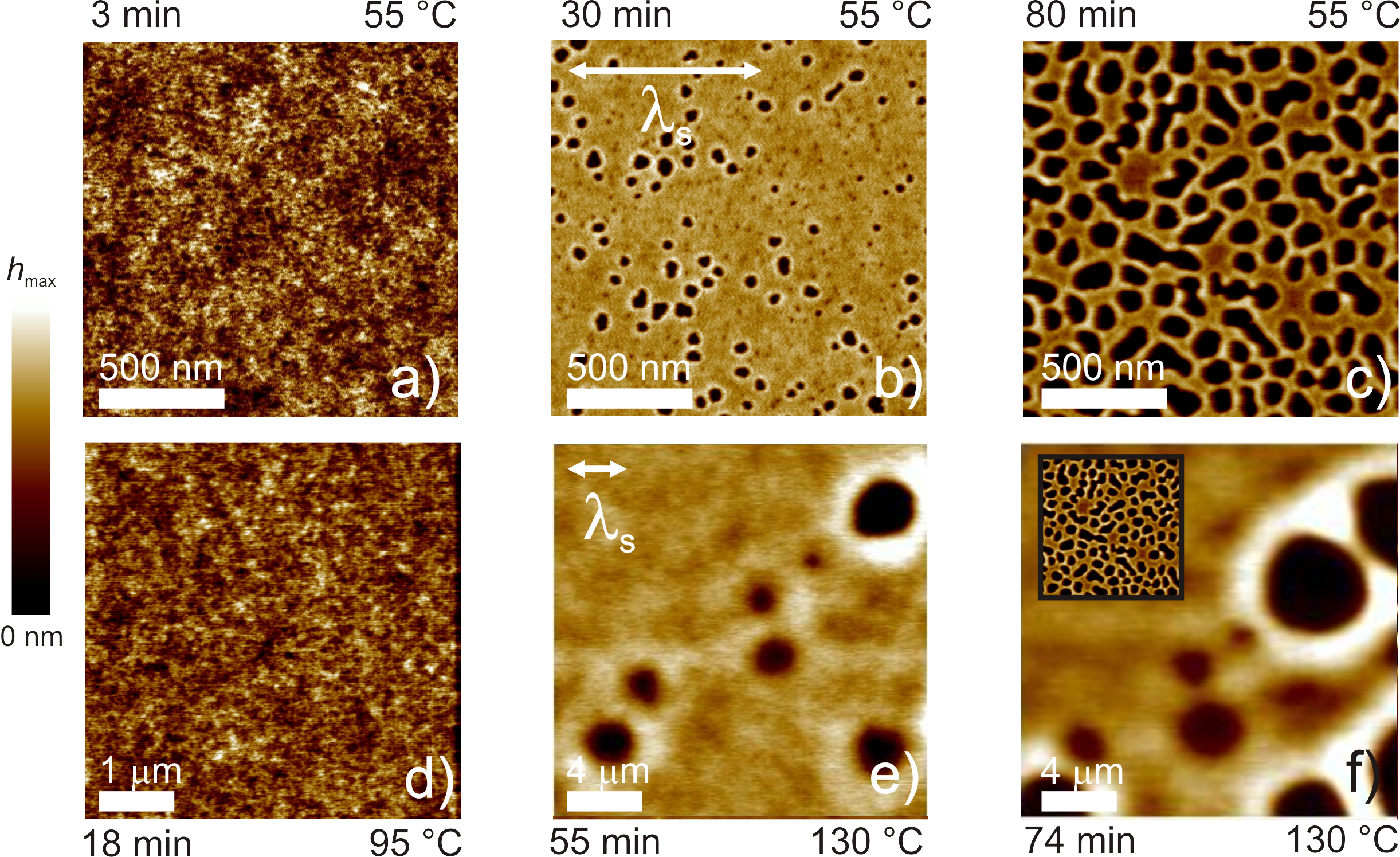

In this work, we present two systems that are nominally susceptible to spinodal dewetting. The first is a polymer film on a silicon wafer with thermally oxidzed layer. The second system is an identical polymer film on an identical wafer, additionally covered with a hydrophobic SAM. Models used to describe the spinodal decomposition on no-slip substrates Seemann et al. (2001); Becker et al. (2003) have been extended to strong slip systems by Rauscher and co-workers Rauscher et al. (2008). With regard to the second system studied here, the no-slip theory Seemann et al. (2001); Becker et al. (2003) predicts that spinodal decomposition of thin PS films may occur, even in cases of strong slip. However, our experimental observations are incompatible with this prediction. Rather, the experimental results provide evidence of a random nucleation process. Thus, in the situation of a film that combines characteristics of the free-standing case (i.e. large slip), with those of a solid support containing energetics promoting spinodal instability, the actual breakup observed is that of a free-standing film.
As a dewetting liquid, polystyrene with a molecular weight of 4.2 kg/mol (PSS, Mainz, Germany) was used. The films with thicknesses were supported on the two types of substrates. The first exhibits a 150 nm SiO2 layer at the top of a Si wafer (Si-Mat, Kaufering, Germany), which we refer to as the SiO2 substrate. To change the solid/liquid boundary condition as well as the surface energy, the second type additionally incorporated a SAM composed of alkylsilane molecules (dodecyltrichlorosilane, DTS, Sigma-Aldrich, Darmstadt, Germany) with nm Fetzer et al. (2005); Fetzer and Jacobs (2007)111The quoted was obtained from nucleated hole growth dewetting experiments of 5.6 kg/mol PS films with 100 nm (at C). This measurement of was not performed with the ultra-thin films discussed here, since the models used Fetzer et al. (2005); Fetzer and Jacobs (2007) to extract are not valid when vdW forces play a major role as with the films studied here. . As described in detail elsewhere Lessel et al. (2015), the RMS surface roughness of a DTS coated SiO2-substrate is identical to a bare one (approx. 0.2 nm), while providing a surface energy mJ/m2 and leading to an equilibrium contact angle for PS. For details see Ref. Lessel et al. (2015). PS was spincast from toluene (chromatography grade, Merck, Darmstadt, Germany) onto a mica sheet (V2 Grade, PLANO GmbH, Wetzlar, Germany) and then annealed at 80 ∘C (C Santangelo and Roland (1998)) for 1 h to release residual stress and solvent. After annealing, the films were floated onto an ultra pure water bath (18.2 M cm, total carbon content 6 ppb, TKA-GenPure, TKA Wasseraufbereitungssysteme GmbH, Braunschweig, Germany), and then transferred to the substrates. By mounting several wafers on a glass slide, it was possible to cover them simultaneously from one PS film, ensuring identical film thickness on multiple samples.
The experiments were performed using in situ high speed atomic force microscopy with scan areas between m2 and m2 (AFM, Dimension FastScan featuring a Dimension heater with Fastscan-A tips, Bruker, Karlsruhe, Germany) 222Influence of the AFM scanning on the dewetting process was excluded by periodically enlarging the scan area and scanning independent areas after a quench; no difference in morphology was observed. . While a detailed study of the temperature dependence is not the subject of this article, we note that in all cases the ultra-thin films on DTS dewetted at temperatures below bulk ; experimentation at these low temperatures, which are significantly less than bulk , was required to enable observation of the dewetting on accessible timescales (tens of minutes). These observations are consistent with dewetting of ultra-thin films on SiO2 substrates observed previously Seemann et al. (2001); Herminghaus et al. (2004); Yang et al. (2010); Xu et al. (2014).
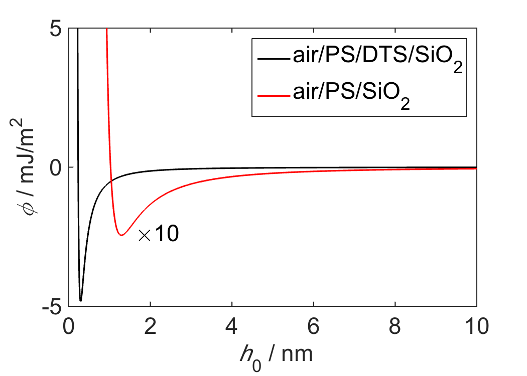
A comparison between the dewetting process of PS films on a hydrophobic DTS substrate and a hydrophilic SiO2 substrate is depicted in Fig. 1. The films exhibit an almost identical film thickness (on SiO2: 6.0(3) nm, on DTS: 5.3(3) nm). Effective interface potentials can be computed according to the layer model developed in Refs. Israelachvili and Tabor (1972); Seemann et al. (2001) and applied to the DTS coated or uncoated SiO2 substrates. The effective interface potential is approximated Seemann et al. (2001); Blossey (2012); Dietrich et al. (2013); Oron et al. (1997) by
| (1) |
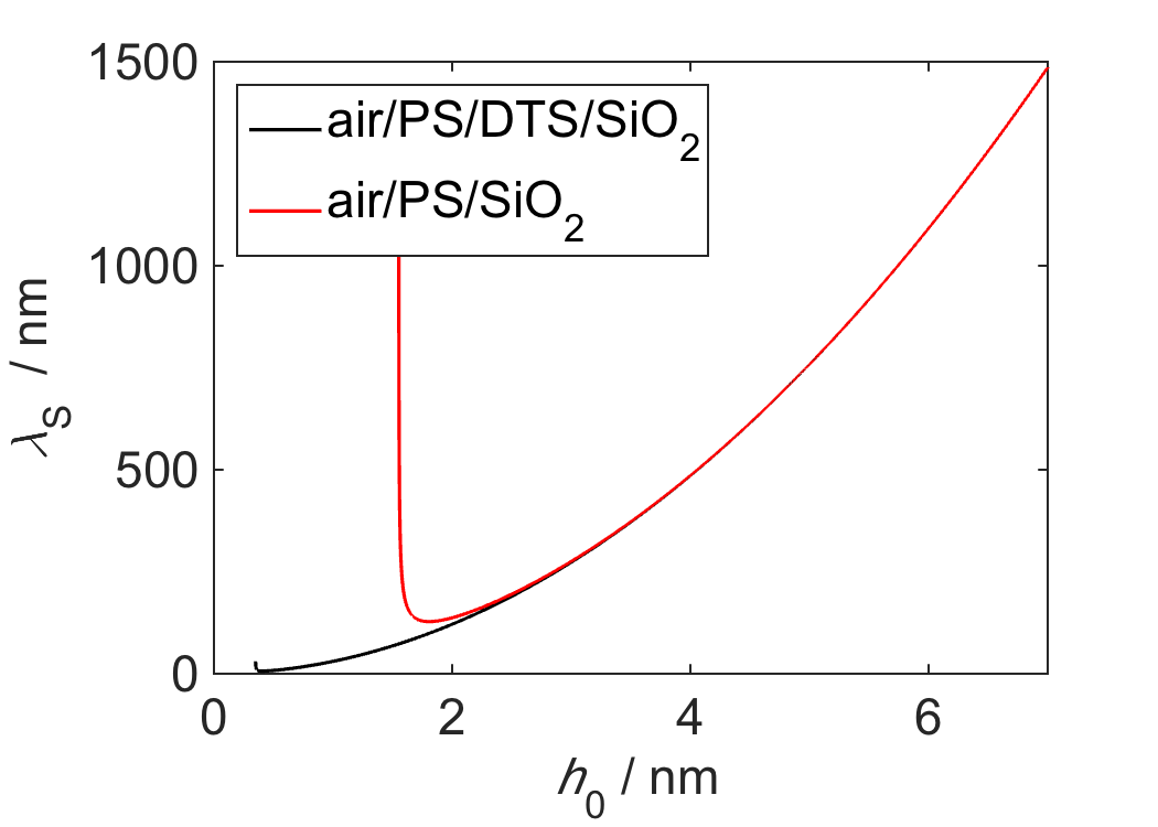
The Hamaker coefficient, J, is taken as that for the air/PS/SiO2 333The buried Si substrate does not need to be included since the SiO2 layer is 150 nm thick, which is much longer than the range of the vdW interactions considered here. system for both cases since the optical index of refraction of DTS is nearly identical to that of SiO2 Seemann et al. (2005); Wasserman et al. (1989); Israelachvili (2011); Lessel et al. (2015). is chosen to obtain the appropriate contact angle through Seemann et al. (2001, 2005); de Gennes et al. (2003), where is the film thickness at which reaches a global minimum and is the polymer/air surface tension. While for SiO2 and DTS are similar, for the two substrates vary substantially with J nm6 and J nm6. In the absence of slip, the expected spinodal wavelengths on both substrates are at least 800 nm, which were calculated as in Ref. Seemann et al. (2001) (see Supplementary Material Figs. S1 and S2). As shown in Fig. 1, we find that the typical hole-to-hole distances in the PS film on the bare SiO2 substrate (lower row) are consistent with this prediction; further evidence for spinodal dewetting as the mechanism for dewetting from SiO2 is provided in the Supplementary Material, Figs. S3 and S4. The spatial structures in the PS film on DTS (upper row), however, are incompatible with the this spinodal breakup scenario, since the distance between hole nuclei is much less than the expected distance.

Hole densities with the number of holes observed in AFM images (scan area ) for both types of substrates are compared in Fig. 1g). The hole densities are plotted as a function of the fractional dewetted area , thereby taking into account the enhanced dewetting dynamics on DTS due to the presence of slip. As such, effects of different temperatures and boundary conditions can be excluded Nguyen et al. (2014). At low hole radii and for early times, hole densities increase as nucleation events occur. After nucleation, hole growth proceeds and the dewetted area increases while holes continue to nucleate in undewetted areas. At large hole radii, coalescence of holes begins and the densities decrease after reaching a maximum. As described above, the typical hole-to-hole distance as depicted in Fig. 1 is consistent with the spinodal wavelength inferred from the effective interface potential Seemann et al. (2001); Becker et al. (2003). Rauscher et al. Rauscher et al. (2008) predicted that the presence of strong slip () would lead to an enlargement of the expected spinodal wavelength, resulting in a decreased hole density. However, the hole densities observed on the DTS substrates are three orders of magnitude higher than those seen on SiO2.
A higher hole density (that is, a smaller typical hole-to-hole distance) does not necessarily exclude a spinodal decomposition of the film. Since holes that originate from a spinodal dewetting process are correlated Jacobs et al. (1998); Herminghaus et al. (1998), spinodal dewetting is not compatible with a random distribution of holes. In order to check for correlations between objects in a space, Minkowski functional analysis Arns et al. (2004); Mecke and Stoyan (2005); Fetzer et al. (2007) has been applied. The Minkowski functionals, which are shown for both SiO2 and DTS in the Supplementary Material, unambiguously exclude spinodal dewetting as the underlying rupture mechanism, and instead prove that the breakup mechanism for films on DTS is a random nucleation process.

To explore the nature of the hole nucleation mechanism of ultra-thin liquid films dewetting from DTS, the influence of the film thickness and dewetting temperature were investigated. In Fig. 2a) the hole density is plotted as a function of dewetted area for films of identical thickness, but different temperatures; an increase in temperature leads to higher maximum hole density. Fig. 2b) shows that a thinner film also leads to a higher maximum hole density. In the context of a random nucleation mechanism, both a higher temperature and thinner film are expected to lead to a higher probability of a nucleation event.
In Fig. 3a) we show AFM height profiles following the nucleation of a hole in a PS film on DTS. At about 20 minutes of annealing, the air/liquid interface makes contact with the substrate, at which time we consider the nucleation event to have taken place with a nucleus (that is, an interface profile, ) in the shape of a cone. Consistent with the ensuing flow following nucleation, this observed cone geometry in Fig. 3a) corresponds with a contact angle Lessel et al. (2015); a lower than equilibrium contact angle leads to a receding contact line and the hole begins to grow. We also note the buildup of a monotonically decaying rim (cf. Fig. 3a) at 38 min) which is a signature of a strong slip boundary condition Fetzer et al. (2005); Bäumchen et al. (2009), i.e. . The monotonicity of the rim precedes the formation of satellite holes Becker et al. (2003) which would be observed for no-slip dewetting characterized by oscillatory height profiles Fetzer et al. (2005); Bäumchen et al. (2009). Thus, the slip boundary condition is a necessary condition to observe these morphologies reminiscent of unsupported films.
To model the hole nucleation process, we assume an idealized conical profile: . Here, is the radial coordinate and is the radius of the hole at the undisturbed film thickness. The inset of Fig. 3a) shows a schematic representation and variable definitions. The excess free energy of such a cone can be written as the sum of two contributions:
| (2) |
where the excess area
| (3) |
is the surface contribution, and the surface tension is J/m2 Wu (1970) at the temperatures investigated here. Since the films are only some nanometers thick, a vdW contribution is necessary and is expressed as
| (4) |
With defined as in Eq. 1, we find that , where is a positive constant depending on the details of the profile and effective interface potential. Here we use and defined below Eq. 1.
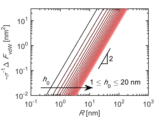
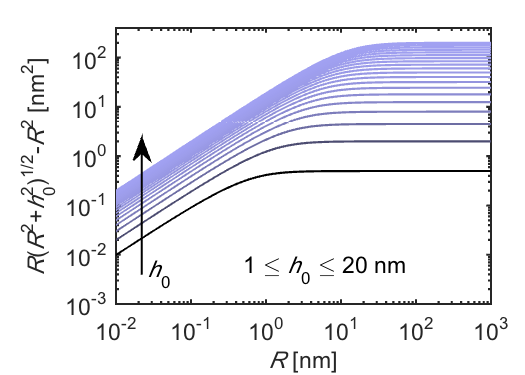
In general, is positive, obtaining a plateau for , while is, for the monotonically increasing presented here, negative (n.b. ). As such, the free energy model of Eq. 2 predicts free energy profiles, shown in the inset of Fig. 3 for nm; plots of the individual components are found in the Supplementary Material. The global maxima define a critical radius, , beyond which the cone grows. can also be obtained from the the observation of hole formation in the AFM measurements (e.g. at 20 min in Fig. 3a)). These obtained from at least 25 holes for a given film, are shown in Fig. 3b). The experimental data is consistent with the predictions of the model developed from Eq. 2 with no free parameters.
While the experimental data and model presented in Fig. 3b) are consistent, the associated energy barriers are larger than the available thermal energy ( nm nm2), yet are comparable to the nuclei energies predicted for unsupported films Croll and Dalnoki-Veress (2010); Rathfon et al. (2011). We may thus consider certain heterogeneities to aid in the nucleation process. For heterogeneous nucleation due to dust contamination, holes typically appear with a monodisperse size distribution Seemann et al. (2001, 2005); by contrast, Fig. 1b) shows PS dewetting from DTS with a broad distribution of hole sizes and Figs. 2a) and b) show a continuous appearance of holes. Furthermore, in previous supported film studies Seemann et al. (2001, 2005), in a majority of the hole centers a nucleus could be clearly identified. Yet for dust-free thin films with typical nanometric dimensions as studied here and elsewhere Croll and Dalnoki-Veress (2010); Rathfon et al. (2011), no nuclei in the form of dust particles can be observed in either experiment (optical resolution in refs. Croll and Dalnoki-Veress (2010); Rathfon et al. (2011), and pixel sizes as small as 1.5 nm in the AFM measurements here). Here we propose as in Jacobs et al. (1998) that heterogeneities in the form of free volume (voids), on the scale of several angstroms Liu et al. (1993); Yu et al. (1994); Ban et al. (1996), may overlap in rare instances to aid in the nucleation of a hole. A detailed statistical analysis of such events is beyond the scope of the present article, yet we hope that future efforts may elucidate the possible role of such processes. Regardless of the important distinction between heterogeneous and homogeneous nucleation, we reiterate that the same film on two different substrates (i.e. SiO2 and DTS) breaks up on different time scales and with a completely different mechanism, despite their similar energetics at the undisturbed film thicknesses.
In conclusion, we have studied dewetting polystyrene films with thicknesses nm on hydrophilic and hydrophobic substrates. In agreement with previous studies, dewetting from the hydrophilic substrates proceeds via spinodal decomposition, i.e. through the amplification of capillary waves. The lower-energy hydrophobic substrates provide a slip boundary condition at the solid/liquid interface, thus bridging the gap between supported film breakup and the bursting of unsupported films. Consistent with previous findings, but here for hydrophobic substrates, we observe a sub- dynamics that is much faster than observed for no-slip substrates. The governing breakup mechanism is also different. We provide evidence that the films, which are nominally susceptible to spinodal decomposition, breakup through a nucleation mechanism if supported by slippery hydrophobic substrates, which is instead consistent with the behaviour observed in unsupported films providing a full slip boundary condition and no substrate surface energy.
The authors acknowledge financial support from the German Science Foundation (DFG), the Graduate College 1276 and NSERC of Canada. OB acknowledges support from the ESPCI Joliot Chair. JDM was supported by LabEX ENS-ICFP: ANR-10-LABX-0010/ANR-10-IDEX-0001-02 PSL. The authors also thank Sabrina Haefner, Mischa Klos, Markus Rauscher and Kari Dalnoki-Veress for insightful discussions.
References
- Baus and Tejero (2008) M. Baus and C. Tejero, Equilibrium Statistical Physics: Phases of Matter and Phase Transitions (Springer, 2008).
- Chaikin and Lubensky (1995) P. Chaikin and T. Lubensky, Principles of Condensed Matter Physics (Cambridge University Press, 1995).
- Israelachvili and Tabor (1972) J. Israelachvili and D. Tabor, Nature 236, 106 (1972).
- Seemann et al. (2001) R. Seemann, S. Herminghaus, and K. Jacobs, Phys. Rev. Lett. 86, 5534 (2001).
- Seemann et al. (2005) R. Seemann, S. Herminghaus, C. Neto, S. Schlagkowski, D. Podzimek, R. Konrad, H. Mantz, and K. Jacobs, Journal of Physics: Condensed Matter 17, S267 (2005).
- Thiele et al. (2001) U. Thiele, M. G. Velarde, and K. Neuffer, Phys. Rev. Lett. 87, 016104 (2001).
- Thiele (2003) U. Thiele, The European Physical Journal E 12, 409 (2003).
- Blossey (2012) R. Blossey, Thin Liquid Films: Dewetting and Polymer Flow (Springer, 2012).
- Dietrich et al. (2013) S. Dietrich, M. Rauscher, and M. Mapiórkowski, “Nanoscale liquid interfaces: Wetting, patterning, and force microscopy at the molecular scale,” (Pan Stanford Publishing, 2013) Chap. 3: Wetting Phenomena on the Nanometer Scale.
- Oron et al. (1997) A. Oron, S. H. Davis, and S. G. Bankoff, Rev. Mod. Phys. 69, 931 (1997).
- Reiter (1992) G. Reiter, Phys. Rev. Lett. 68, 75 (1992).
- Jacobs et al. (1998) K. Jacobs, S. Herminghaus, and K. R. Mecke, Langmuir 14, 965 (1998).
- de Gennes et al. (2003) P. de Gennes, F. Brochard-Wyart, and D. Quéré, Capillarity and Wetting Phenomena: Drops, Bubbles, Pearls, Waves (Springer, New York, 2003).
- Vrij (1966) A. Vrij, Discuss. Faraday Soc. 42, 23 (1966).
- Becker et al. (2003) J. Becker, G. Grün, R. Seemann, H. Mantz, K. Jacobs, K. Mecke, and R. Blossey, Nat. Mat. 2, 59 (2003).
- Wang and Tsui (2006) Y. J. Wang and O. K. C. Tsui, Langmuir 22, 1959 (2006).
- Israelachvili (2011) J. Israelachvili, Intermolecular and Surface Forces, 3rd ed. (Academic Press, 2011).
- Debrégas et al. (1995) G. Debrégas, P. Martin, and F. Brochard-Wyart, Physical Review Letters 75, 3886 (1995).
- Dalnoki-Veress et al. (1999) K. Dalnoki-Veress, B. Nickel, C. Roth, and J. Dutcher, Physical Review E 59, 2153 (1999).
- Roth and Dutcher (2006) C. Roth and J. Dutcher, Journal of Polymer Science Part B: Polymer Physics 44, 3011 (2006).
- Croll and Dalnoki-Veress (2010) A. Croll and K. Dalnoki-Veress, Soft Matter 6, 5547 (2010).
- Rathfon et al. (2011) J. M. Rathfon, R. W. Cohn, A. J. Crosby, and G. N. Tew, Macromolecules 44, 134 (2011).
- Fetzer et al. (2005) R. Fetzer, K. Jacobs, A. Münch, B. Wagner, and T. P. Witelski, Phys. Rev. Lett. 95, 127801 (2005).
- Fetzer and Jacobs (2007) R. Fetzer and K. Jacobs, Langmuir 23, 11617 (2007).
- Gutfreund et al. (2013) P. Gutfreund, O. Bäumchen, R. Fetzer, D. van der Grinten, M. Maccarini, K. Jacobs, H. Zabel, and M. Wolff, Physical Review E 87, 012396 (2013).
- Bäumchen et al. (2009) O. Bäumchen, R. Fetzer, and K. Jacobs, Phys. Rev. Lett. 103, 247801 (2009).
- Rauscher et al. (2008) M. Rauscher, R. Blossey, A. Münch, and B. Wagner, Langmuir 24, 12290 (2008).
- Note (1) The quoted was obtained from nucleated hole growth dewetting experiments of 5.6\tmspace+.1667emkg/mol PS films with \tmspace+.1667em100\tmspace+.1667emnm (at C). This measurement of was not performed with the ultra-thin films discussed here, since the models used Fetzer et al. (2005); Fetzer and Jacobs (2007) to extract are not valid when vdW forces play a major role as with the films studied here.
- Lessel et al. (2015) M. Lessel, O. Bäumchen, R. Fetzer, M. Klos, H. Hähl, R. Seemann, and K. Jacobs, Surface and Interface Analysis 47, 557 (2015).
- Santangelo and Roland (1998) P. Santangelo and C. Roland, Macromolecules 31, 4581 (1998).
- Note (2) Influence of the AFM scanning on the dewetting process was excluded by periodically enlarging the scan area and scanning independent areas after a quench; no difference in morphology was observed.
- Herminghaus et al. (2004) S. Herminghaus, R. Seemann, and K. Landfester, Physical Review Letters 93, 017801 (2004).
- Yang et al. (2010) Z. Yang, Y. Fujii, F. Lee, C.-H. Lam, and O. Tsui, Science 328, 1676 (2010).
- Xu et al. (2014) J. Xu, L. Ding, J. Chen, S. Gao, L. Li, D. Zhou, X. Li, and G. Xue, Macromolecules 47, 6365 (2014).
- Note (3) The buried Si substrate does not need to be included since the SiO2 layer is 150 nm thick, which is much longer than the range of the vdW interactions considered here.
- Wasserman et al. (1989) S. Wasserman, G. Whitesides, I. Tidswell, B. Ocko, P. Pershan, and J. Axe, Journal of the American Chemical Society 111, 5852 (1989).
- Nguyen et al. (2014) T. D. Nguyen, M. Fuentes-Cabrera, J. D. Fowlkes, and P. D. Rack, Phys. Rev. E 89, 032403 (2014).
- Herminghaus et al. (1998) S. Herminghaus, K. Jacobs, G. Schatz, K. Mecke, J. Bischof, A. Fery, M. Ibn-Elhaj, and S. Schlagowksi, Science 282, 916 (1998).
- Arns et al. (2004) C. Arns, M. Knackstedt, and K. Mecke, Colloids and Surfaces A 241, 351 (2004).
- Mecke and Stoyan (2005) K. Mecke and D. Stoyan, Biometrical Journal 47, 1 (2005).
- Fetzer et al. (2007) R. Fetzer, M. Rauscher, R. Seemann, K. Jacobs, and K. Mecke, Phys. Rev. Lett. 99, 114503 (2007).
- Wu (1970) S. Wu, Journal of Physical Chemistry 74, 632 (1970).
- Liu et al. (1993) J. Liu, Q. Deng, and Y. Jean, Macromolecules 26, 7149 (1993).
- Yu et al. (1994) Z. Yu, U. Yashi, J. McCervey, A. Jamieson, and R. Simha, Journal of Polymer Science: Part B: Polymer Physics 32, 2637 (1994).
- Ban et al. (1996) M. Ban, M. Kyoto, A. Uenono, T. Kawano, and S. Tanicawa, Journal of Polymer Science Part B: Polymer Physics 34, 1189 (1996).
Supplementary Material for: Nucleated dewetting in supported ultra-thin liquid films with hydrodynamic slip
Effective Interface Potential and Spinodal Wavelength
.1 Minkowski Measures; Power Spectral Densities
Different methods are suitable to analyze correlations in point patterns, in our case, Minkowski measures have shown to be extremely convenient, since they are able to find not only two-point correlations (like a Fourier transformation oder a pair correlation function g(r)), but also capture higher-order correlations Mecke (1998). In the very same way as in earlier studies, we have analyzed the statistical distribution of the hole sites by Minkowski measures Jacobs et al. (1998); Herminghaus et al. (1998). In two dimensions (like for our point set of hole sites), three Minkowski measures completely describe the distribution and there are analytical descriptions of what to expect for a random (Poissonian) set of sites. This is the clear strength of Minkowski measures, a random process can unambiguously be detected analytically. Deviations of that expectation then show that the hole sites are correlated.
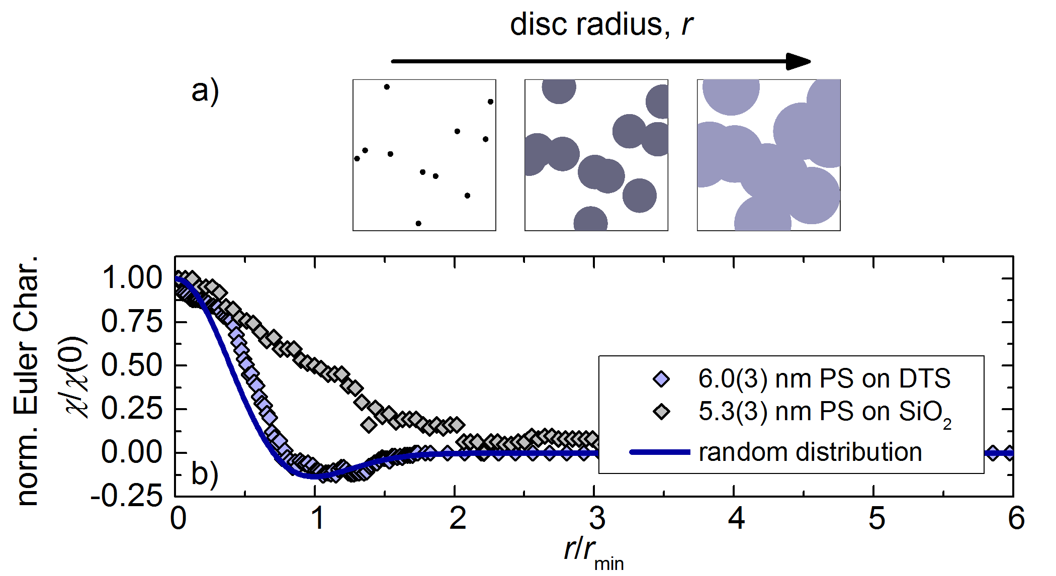
One Minkowski measure is the Euler characteristic, , which quantifies the connectivity of a distribution of objects – in this case the distribution and connectivity of the holes seen in Fig. 1. is computed by placing disks of radius at the center of every hole (see Fig. S4a)), and is thereby only a function of the number of holes and the disk radius, . It is also possible to analytically calculate for a Poisson distribution of holes, as described in Refs. Chiu et al. (1996); Arns et al. (2004); Mecke and Stoyan (2005). Fig. S4b) depicts the Euler characteristic of the experiments shown on Fig. 1 and that obtained by the theory for a Poisson distribution (eq. 24 in Arns et al. (2004)):
| (S5) |
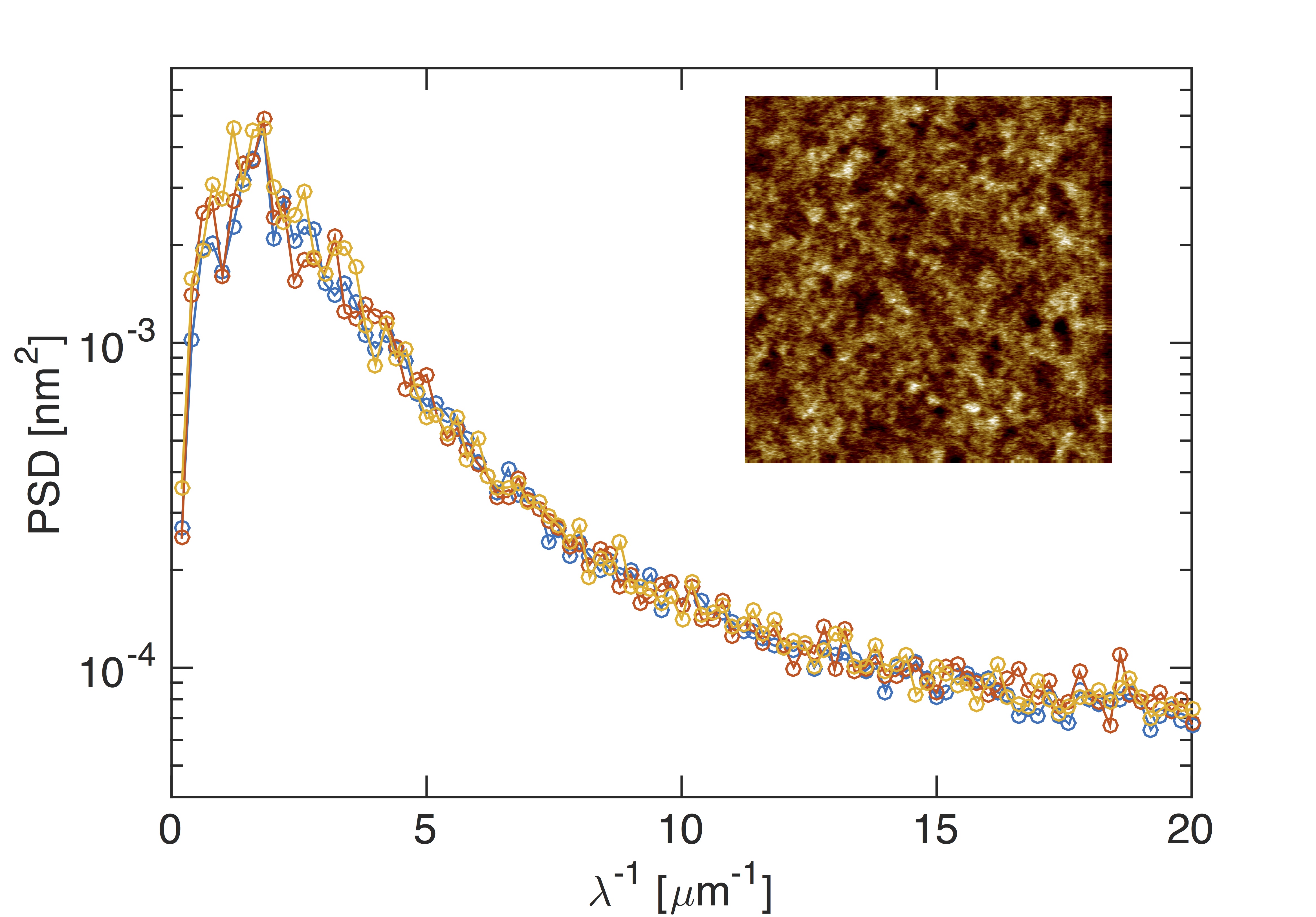
where is the number density of disks, easily accessed from the experimental data. The prediction of the Poisson distribution, a universial curve in the normalized representation of Fig. S4b), is not followed by the hole formation of spinodally dewetting films, as seen in Becker et al. (2003); Herminghaus et al. (1998) and confirmed here for the liquid films on the bare SiO2 substrate; the power spectral densities of Fig. S4 show furthermore a well defined peak at the expected spinodal wavelength, giving further evidence for the spinodal mechanism governing the film breakup on SiO2 substrates. In contrast, the Euler characteristic for dewetting films on DTS is well captured by the uncorrelated random distribution, which proves that the dewetting process on DTS cannot originate from a spinodal process.
.2 Free Energy Components
References
- Mecke (1998) K. Mecke, International Journal of Modern Physics B 9, 861 (1998).
- Jacobs et al. (1998) K. Jacobs, S. Herminghaus, and K. R. Mecke, Langmuir 14, 965 (1998).
- Herminghaus et al. (1998) S. Herminghaus, K. Jacobs, G. Schatz, K. Mecke, J. Bischof, A. Fery, M. Ibn-Elhaj, and S. Schlagowski, Science 282, 916 (1998).
- Chiu et al. (1996) S. Chiu, D. Stoyan, W. S. Kendall, and J. Mecke, Stochastic geometry and its applications, Vol. 3 (Wiley, 1996).
- Arns et al. (2004) C. Arns, M. Knackstedt, and K. Mecke, Colloids and Surfaces A 241, 351 (2004).
- Mecke and Stoyan (2005) K. Mecke and D. Stoyan, Biometrical Journal 47, 1 (2005).
- Becker et al. (2003) J. Becker, G. Grün, R. Seemann, H. Mantz, K. Jacobs, K. Mecke, and R. Blossey, Nat. Mat. 2, 59 (2003).