On the Difficulty of Inserting Trojans in Reversible Computing Architectures
Abstract
Fabrication-less design houses outsource their designs to 3rd party foundries to lower fabrication cost. However, this creates opportunities for a rogue in the foundry to introduce hardware Trojans, which stay inactive most of the time and cause unintended consequences to the system when triggered. Hardware Trojans in traditional CMOS-based circuits have been studied and Design-for-Trust (DFT) techniques have been proposed to detect them.
Different from traditional circuits in many ways, reversible circuits implement one-to-one, bijective input/output mappings. We will investigate the security implications of reversible circuits with a particular focus on susceptibility to hardware Trojans. We will consider inherently reversible circuits and non-reversible functions embedded in reversible circuits.
I Introduction
Most established computing paradigms are not reversible including the building block operations such as NAND/NOR that they use. While it is possible to infer the inputs when a NAND outputs a 0 (then, both inputs are 1), it is not possible to unambiguously infer the inputs if the NAND outputs 1.
Alternative computing paradigms are gaining interest. Reversible computations are bijective -input -output functions that map each input combination to a unique output combination. Reversibility is useful in implementing quantum computing architectures, since quantum computations are inherently reversible [1, 2, 3]. In fact, many components of quantum computers such as the database in case of Grover’s Search [4] or modular exponentiation in case of Shor’s algorithm [5]) are reversible. Hence, researchers built a reversible circuit first (using methods e.g. reviewed in [6, 7]), which are afterwards mapped into a corresponding quantum circuit (using methods proposed in [2, 8]).
Besides, reversible logic continues to grow and show promise in low power computing, [9, 10, 11], adiabatic computing [12], circuit verification [13], and optical computing [14, 15].
Reversible circuits differ from conventional circuits in many ways. In order to implement reversibility, fan-out and feedback are not allowed and each circuit is realized as a cascade of reversible gates. In this paper, we will study the supply chain security of reversible circuits with a focus on hardware Trojans. Effects of different types of Trojans are studied and simple yet effective defenses are proposed.
The paper is organized as follows. Section II introduces reversible logic. Section III presents the threat model in reversible circuits. In Section IV, we conduct studies on small-sized hardware Trojans in reversible circuits. Based on the characteristics of reversible circuits, simple yet effective methods are proposed to disable inserted hardware Trojans in Section V. Experiments on effectiveness of the proposed methods are presented in Section VI and Section VII concludes the paper.
II Review on Reversible Logic
Definition 1.
A Boolean function is reversible if it maps each input combination to a unique output combination.
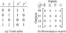
A reversible boolean function with inputs can be viewed as a mapping of a to itself. A reversible function can be represented as a truth table or a permutation matrix as shown in Fig. 1. Each input uniquely maps to an output and vice versa, i.e., the mapping is a bijection.
Reversible circuits synthesized from reversible functions typically are cascades of reversible gates. In addition to components that are naturally reversible such as wire, Not, and Swap gates, Fredkin, Toffoli and Feynman are frequently used in the reversible/quantum computing literature [16].
Definition 2.
A input, output gate is reversible if it realizes a reversible function.
Toffoli gate will be considered in this paper. A -input Toffoli gate has control lines and 1 target line, where the control lines can be either positive or negative.
Definition 3.
A Toffoli gate passes k-1 control lines unchanged, and inverts the target line if values of all its positive (negative) control lines are 1 (0).
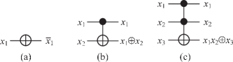
For simplicity, only positive control lines are considered in this paper. Consider the general Toffoli gate where the line is the target line, then
is a NOT gate, and is a controlled-NOT gate (CNOT). Symbols of , and are shown in Fig. 2.
Arbitrary functions can be implemented as reversible circuits as cascades of reversible gates. Many approaches have been proposed to synthesize reversible circuits [17, 18, 19, 20, 21, 22, 23]. Ancillary inputs and garbage outputs are necessary when embedding non-reversible function into a reversible structure.
Example 1.
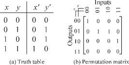
The half adder truth table is shown in Fig. 3(a). Input combinations 01 and 10 map to the same output 01. Fig. 3(b) shows its permutation matrix. Non-reversibility can be seen in the second row (output 01) of the matrix, which has two 1s in the row. The entries in the second and third columns represent input combinations 01 and 10. All 0s in the last row of the matrix violates reversibility, because no input combination is mapped to this output 11.
To make the half adder reversible, the first step is to add garbage output(s) to make sure each input pattern has a corresponding unique output pattern. In a half adder, there are two input patterns that map to one output pattern, so adding one garbage output bit is enough to create a unique input-output mapping. Next, we should make sure that the number of inputs and the number of outputs are equal. One ancillary (constant) input is added to make the number of inputs and outputs same, as shown in TABLE II(a). Any assignment to the garbage output g and the ancillary input a is a valid assignment as long as it creates a reversible function. Most prior work assigned constant values to ancillary inputs as shown in TABLE II(b).
| 0 | 0 | 0 | 0 | 0 | * |
| 0 | 0 | 1 | |||
| 0 | 1 | 0 | 0 | 1 | * |
| 0 | 1 | 1 | |||
| 1 | 0 | 0 | 0 | 1 | * |
| 1 | 0 | 1 | |||
| 1 | 1 | 0 | 1 | 0 | * |
| 1 | 1 | 1 |
| 0 | 0 | 0 | 0 | 0 | 0 |
|---|---|---|---|---|---|
| 0 | 0 | 1 | 0 | 0 | 1 |
| 0 | 1 | 0 | 0 | 1 | 0 |
| 0 | 1 | 1 | 1 | 0 | 0 |
| 1 | 0 | 0 | 0 | 1 | 1 |
| 1 | 0 | 1 | 1 | 1 | 0 |
| 1 | 1 | 0 | 1 | 0 | 1 |
| 1 | 1 | 1 | 1 | 1 | 1 |
III The Threat Model
III-A Hardware Trojans
Globalization of the integrated circuit (IC) design flow has raised security concerns including malicious circuit modifications, referred as Hardware Trojans. A hardware Trojan remains inactive and poses no threat to its host circuit until it is triggered. When triggered it will alter the original function [24, 25]. Hardware Trojans are hard to detect since they are stealthy: 1) they are designed to be triggered under extremely rare conditions and 2) they are usually much smaller than their host circuits. Various Design-for-Trust techniques have been developed to detect and prevent hardware Trojans and/or recover from faults created by them [26, 27]. One set of techniques increase the switching probability of the normally inactive nets and hence facilitating the triggering and detecting processes [28]. Another set of techniques detect hardware Trojans by enhancing and monitoring the side-channel effects [29, 30, 31]. However, all of these techniques focus on CMOS-based designs that are inherently non-reversible.
III-B Trojans vs. Faults in Reversible Logic
Hardware Trojans are to some extent similar to faults as they all affect the outputs when triggered. Extending from this point, a hardware Trojan may be categorized as a new type of faults where the host circuit contains extra gates. However, the key difference between faults and hardware Trojans is their origins: Faults originate from imperfect fabrication process or environment disturbance, while hardware Trojans are well-designed and carefully inserted by attackers with a detailed knowledge of the host circuit. From the point of circuit testing, a common practice is to focus on a limited set of fault models and assume a single-gate failure [32, 33, 34, 35]. On the other hand, the size, structure, and functionality of a Trojan can be unknown and unforeseeable, which makes test patterns for Trojan detection much harder to generate.
Further, the excellent controllability and reversibility of reversible circuits makes testing for faults much easier. In a reversible circuit, reversibility exists not only between primary inputs and primary outputs but also between inputs and outputs of any internal gates. The inputs to any internal gate can be controlled easily from the primary inputs and the outputs of any internal gate can be observed at the primary outputs. The excellent controllability and reversibility, however, benefit Trojan attackers as well. This is because all the nodes will have the same switching probability if random inputs are applied. As a result, a Trojan can be inserted at any position in a reversible circuit and receive the same triggering probability, which significantly increases the search space for detection. This is not the case in CMOS-based circuits where the switching probabilities of nodes vary significantly and inactive nodes are considered the best candidates for Trojan insertion [28].
III-C The Threat Model
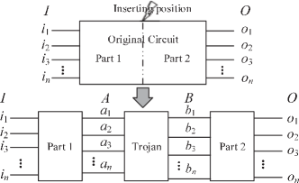
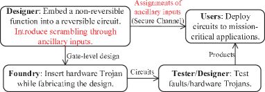
Consider an attacker in the foundry who tries to insert a hardware Trojan during fabrication. The Trojan impacts the output of the host design when triggered. Fig. 4 shows the supply chain of integrated circuits.
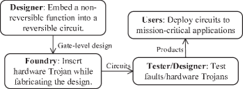
The Trojan can be a simple -Toffoli gate or complex one consisting of multiple -Toffoli gates. can be different values for different gates. The hardware Trojan maintains reversibility since it uses Toffoli gates.
IV Hardware Trojans in Reversible Circuits
Small hardware Trojans are always favored due to their minimal side-channel impacts on the host circuit including power, dimensions and delay. We start our analysis from small-sized Trojans to a general case.
IV-A Single-Gate Trojans
Consider a reversible circuit with primary inputs/outputs and a -Toffoli Trojan gate. This Trojan will pass its input unchanged if at least one of its control lines is set to 0 and will affect the original circuit function when it is triggered, i.e., when all its control lines are set to 1.
Theorem 1.
A single-gate Trojan in a reversible circuit can be activated by at least two input patterns.
Proof.
When the Trojan consists of n-1 control lines and 1 target line, it can be triggered by assigning each control line to 1, and the target line to either 1 or 0. So there are two input patterns that can activate the Trojan. When the number of control lines is (), there are patterns that can trigger the Trojan. As a result, there are at least 2 patterns that can activate the Trojan. ∎
Since the tester does not know which line will be the target line in the Trojan, between the two triggering patterns, the pattern that applies 1 to all lines is more effective in detecting a single-gate Trojan. The pattern, which needs to apply 0 to the target line of a Trojan, is less effective since the tester must try out all lines to guarantee the triggering. This results in the a set of one-cold patterns where each of the inputs takes turn to be 0. We hence refer the former as the All-1 pattern, and the latter as the set of One-Cold patterns. According to the following analysis, the All-1 pattern is more efficient in triggering a single-gate Trojan, while the set of One-Cold patterns are useful in triggering any Trojans consisting of 4 gates.
The ALL-1 pattern: Since most of the times a Trojan is inserted somewhere in the middle of the circuit as shown in Fig. 5, applying an All-1 triggering pattern at and observing the error at output are necessary.
Theorem 2.
It is sufficient to apply at most patterns at to trigger a single-gate Trojan inserted at ANY position in an -gate reversible circuit, and observe the Trojan effects at .
Proof.
Controllability: In order to apply the All-1 pattern at Trojan input , the tester needs to find the corresponding pattern at circuit input . Luckily, due to the reversibility of the circuit and each sub-circuit (like Part 1 in the figure), there is always a pattern at that maps to the triggering pattern at .
Observability: Also due to the reversibility of Part 2, the effect induced by a triggered Trojan will always propagate an unexpected output observed at .
The number of patterns: The pattern at , however, depends on the function of Part 1 in Fig. 5, which in turn depends on the position of the Trojan. Since in an -gate reversible host circuit there are positions for inserting a Trojan, a input patterns at will guarantee the triggering of a single-gate Trojan inserted at ANY position.
These input patterns are sufficient to detect a single-gate Trojan. ∎
For easy reference, we still use the All-1 pattern (at ) to represent the patterns at .
One-Cold Patterns:
Theorem 3.
It is sufficient to apply at most patterns at to trigger a single-gate Trojan inserted at ANY position in a -gate reversible circuit, and observe its effect at .
The proof is similar to Theorem 2. Since each set of One-Cold patterns consists of patterns for an -line reversible circuit, the total number of inputs patterns that guarantee the detection of any single-gate Trojan is . Similar to the All-1 pattern, we use the set of One-Cold patterns at to represent the patterns at .
IV-B Two-Gate Trojans
For a two-gate Trojan, 2 cases arise.
Case 1: The two gates have different target lines as shown in Fig. 6(a). Triggering one of the gates triggers the Trojan. Both the All-1 pattern and the set of One-Cold patterns can detect such two-gate Trojans. Thus, detection of this two-gate Trojan only needs partial triggering.
Case 2: The two gates have the same target line but different control lines, as shown in Fig. 6(b).
Theorem 4.
At least one pattern from the set of One-Cold patterns can detect the two-gate Trojan in Case 2 where both gates control the same target line.
Proof.
Since the two gates have different control lines, there is at least one One-Cold pattern among the set of patterns that will trigger only one of the two gates, i.e., the only is applied to a control line of the other gate. Since the other gate is not triggered, the effect induced by the triggered gate can always be passed through the down stream sub-circuit to output , which leads to its detection. ∎
The All-1 pattern always trigger both gates. Since these two gates control the same target line, this target line will start from and is inverted to by the first gate, then inverted back to by the second gate.
Note that there is a third case where both gates have the same control lines and control the same target line. This is a dummy case since both gates are either not triggered or triggered but the second gate always cancels the effect induced by the first gate. While this Trojan may still affect the host’s side-channel parameters, we will leave them for future work.
IV-C Three-Gate Trojans
For a three-gate Trojan, 5 cases are illustrated in Fig. 7.
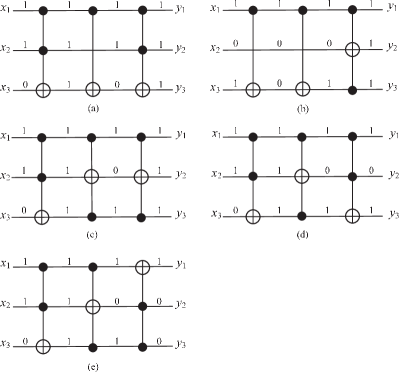
Case 1: Three gates control the same target line shown in Fig. 7(a). Consider the All-1 pattern at and the One-Cold pattern at where the 0 bit is on the target line. Both patterns will trigger all three gates and the target line will be inverted three times and end up being 0 or 1, respectively. This will result in an unexpected output and hence the Trojan is detected.
Case 2: The former two gates control the same target line. Triggering the third gate or triggering one of the former two gates will guarantee detection of the Trojan. The third gate is triggered by the All-1 pattern at or by the One-Cold pattern where the 0 bit is on its target line as shown in Fig. 7(b). When the former two gates have different control lines, one of them can be triggered by applying One-Cold patterns; this is Case 2 of 2-gate Trojans. When they have the same control lines, we can ignore them as mentioned in Case 3 of 2-gate Trojans.
Case 3: The last two gates control the same target line as shown in Fig. 7(c). Triggering the first gate will detect of the Trojan. Both the All-1 input pattern and the One-Cold input pattern at where the 0 bit is on the target line of the first gate will trigger it.
Case 4: The first and the last gates have the same target line as shown in Fig. 7(d). This forms a symmetric structure; effects brought by the first gate will be canceled by the third gate when the middle gate is not triggered. The question then is if the middle gate is guaranteed to be detected by using either the All-1 pattern or the set of One-Cold patterns. The answer is yes. Consider a One-Cold pattern at (which is also the input to the first gate) where the 0 bit is on the target line of the first gate. Since all the other bits are 1, the first gate is triggered and its target line flips . This results in an All-1 pattern at the input of the middle gate triggering it. The All-1 pattern at will not guarantee triggering of the middle gate. This is because the 1 on the target line of the first gate is inverted to 0 and this 0 may happen to be on the control line of the middle gate.
Case 5: All 3 gates control different target lines as shown in Fig. 7(e). Triggering any of these gates is enough to detect the Trojan and this can be achieved by either the All-1 pattern or the set of One-Cold patterns.
In summary, the set of One-Cold patterns guarantee the detection of any 3-gate Trojans inserted at any position of the host circuit.
IV-D Four-Gate Trojans
One can similarly conclude that the set of One-Cold patterns guarantees the detection of any 4-gate Trojan inserted at any place in the host circuit.
IV-E Symmetric Trojans
For a Trojan with more than four gates, a sophisticated attacker may hide the impact of input patterns with symmetric parts as shown in Fig. 8(a). Unfortunately, neither the All-1 pattern nor the set of One-Cold patterns guarantees detection of such a Trojan.
In Fig. 8(a), a symmetric Trojan is represented as , where , and are the left, middle and the right part of the symmetric Trojan. The symmetric parts, and , have at least two gates each and have the same set of control lines. They will be triggered by the same set of patterns and control the same set of target lines. The triggering of the symmetric parts and does not impact the output of the host circuit. Thus such symmetric Trojans can be detected by triggering . However, both patterns fail to do so.
-
•
When the All-1 pattern arrives at , will be triggered and its target lines will be inverted to 0s. Since ’s target lines are the control lines to , won’t be able to see all 1s at its input and will remain inactive.
-
•
If the set of One-Cold patterns are applied at , since there is only one 0 bit in the pattern, at most one of the ’s target lines will be inverted to 1. won’t see all 1s at its input either and will remain inactive.
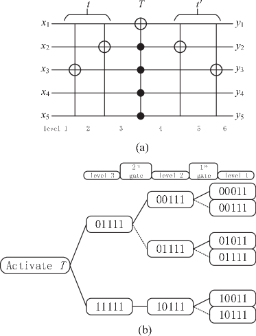
Fig. 8(b) shows how to trigger . The triggering of requires the input pattern in level 3 to be or . If we want to apply in level 3, the input pattern in level 2 has to be when the gate is triggered (solid line) or when the gate is not triggered (dotted line). The remaining steps are similarly derived. Each path in the diagram indicates at least one design of a symmetric Trojan. And each leaf of a path represents the pattern that arrives at the Trojan and can eventually activate part.
As the All-1 and the set of One-Cold patterns cannot guarantee the detection of symmetric patterns, we propose to thwarting hardware Trojans by disabling them in the functional mode. The next section presents the proposed technique.
V Detecting and Thwarting Trojans in Reversible Circuits
V-A Generalizing to Arbitrary Trojans
According to the principle of reversibility in Fig. 5, a primary input pattern maps correctly to a primary output pattern only if the corresponding intermediate result is the same as , i.e., the Trojan passes its input unchanged. Primary input patterns that make an inconsistent mapping between and trigger the Trojan, resulting in unexpected primary outputs. Since a Trojan is reversible by itself, the size of its truth table is the same as its host circuit. A Trojan should not be triggered for all the entries in its truth table where the input equals the output (equal I/O pairs).
We can use to represent the difficulty of triggering a Trojan. The larger the D, the more difficult it is to detect/trigger the Trojan when random patterns are applied.
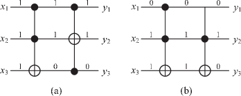
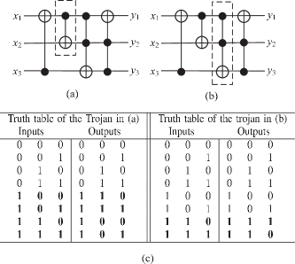
Fig. 9 shows reversible circuits with a Trojan gate in dotted rectangle. In Fig. 9(a), the Trojan gate has a single control and target line. When the control line is set to 1, the Trojan is activated and . In Fig. 9(b), the Trojan gate has 2 control lines and 1 target line. It will be activated only when both its control lines receive 1. This translates to 6-out-of-8 I/O pairs and results in . The truth tables of the two Trojans are shown in Fig. 9(c), where triggering I/O pairs are in bold.
V-B Detecting Trojans in Reversible Circuits w/o Ancillary Inputs
In inherently reversible circuits, the probability that each line is a 1 (or 0) is 0.5. Hence applying random test patterns at primary inputs can be a basic detection method since the randomness at the primary inputs will be passed to the Trojan’s input no matter where it is inserted. Hence the difficulty/chance of detecting a random Trojan in inherently reversible circuits is directly related to the of this Trojan.
V-C Detecting Trojans in Reversible Circuits w/ Ancillary Inputs
Non-reversible functions, such as add and multiply, can be embedded into a reversible circuit. This is a more popular case since most functions are not reversible. The embedding process first adds garbage outputs to map each possible input to a unique output, and then adds ancillary inputs to make the number of inputs equal to the number of outputs. Ancillary inputs can be assigned random values just like primary inputs when the reversible circuit is under testing and assigned a constant value (0 or 1) in the functional mode.
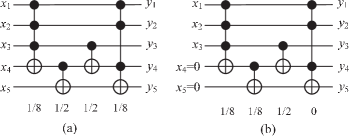
Let us use the half adder example. The truth table of a half adder embedded in a reversible circuit is shown in TABLE II(b). In the test mode, all entries of the truth table can be exercised. In the functional mode, only the bold entries are visited. If a triggering pattern of a Trojan is one of these never-reached entries, it will never be received by the Trojan in the functional mode. If all triggering patterns of a Trojan are the never-reached entries, the Trojan is never triggered in the functional mode. This is illustrated in Fig. 10. Each gate is annotated with its triggering probability. The ancillary inputs result in a 0 triggering probability of the fourth gate in Fig. 10(b).
This property presents a dilemma to a Trojan designer. On one hand, to avoid being triggered and hence detected in the test mode where all inputs, including both primary and ancillary inputs could be exercised for testing, Trojan designers have to minimize the number of patterns that can trigger their Trojans. That is, make close to 1. On the other hand, the less the number of triggering patterns, the higher the chance they are never exercised in the functional mode where ancillary inputs will only take fixed values. This can be exploited by the designers of host circuits to (partially or completely) disable Trojans in the functional mode.
V-D Scramble Inputs and Outputs to Thwart Trojans
Consider scrambling of inputs. The scrambling can be achieved in two ways. First, one can scramble the inputs to the original function by exploiting the existing ancillary inputs. Second, introduce ancillary inputs to improve scrambling. The designer scrambles in the design phase and keeps it secret from the foundry, as shown in Fig. 11. Only authorized users obtain and use the scrambling code (the assignments to ancillary inputs).
V-D1 Exploit Ancillary Inputs
For simplicity, ancillary inputs are usually assigned all 0 or all 1 during functional mode. The truth table of decod24_10 with two ancillary inputs being 0 is shown in TABLE III(a). This assignment is easy to crack by an attacker since only two guesses are necessary. Scrambling can be more sophisticated, since the ancillary inputs do not have to be a fixed constants. They can be designed to take any values in the functional mode, as long as the resulting truth table is reversible.
Starting with a reversible circuit with primary inputs and ancillary inputs that take all 0 (or all 1) for all primary input patterns, the first thing we can do is to make some of the ancillary inputs 0 and the rest 1. One example is shown in TABLE III(b). The number of guesses for the values taken by ancillary inputs will increase up to .
To further decrease successful guessing, the values of ancillary inputs can be randomly chosen for each input pattern, as long as these input patterns map to correct output patterns. One example is shown in TABLE III(c). This makes the number of guesses up to . Additional ancillary inputs can be added to improve scrambling, at extra cost.
| 0 0 0 0 | 0 0 0 1 |
| 0 0 0 1 | 0 0 0 0 |
| 0 0 1 0 | 0 1 1 0 |
| 0 0 1 1 | 0 1 1 1 |
| 0 1 0 0 | 0 0 1 0 |
| 0 1 0 1 | 0 1 0 1 |
| 0 1 1 0 | 1 1 0 0 |
| 0 1 1 1 | 0 0 1 1 |
| 1 0 0 0 | 0 1 0 0 |
| 1 0 0 1 | 1 0 0 1 |
| 1 0 1 0 | 1 1 1 0 |
| 1 0 1 1 | 1 1 1 1 |
| 1 1 0 0 | 1 0 0 0 |
| 1 1 0 1 | 1 1 0 1 |
| 1 1 1 0 | 1 0 1 0 |
| 1 1 1 1 | 1 0 1 1 |
| 0 0 0 0 | 0 1 1 0 |
| 0 0 0 1 | 0 0 0 0 |
| 0 0 1 0 | 0 0 0 1 |
| 0 0 1 1 | 0 1 1 1 |
| 0 1 0 0 | 1 1 0 0 |
| 0 1 0 1 | 0 1 0 1 |
| 0 1 1 0 | 0 0 1 0 |
| 0 1 1 1 | 0 0 1 1 |
| 1 0 0 0 | 1 1 1 0 |
| 1 0 0 1 | 1 0 0 1 |
| 1 0 1 0 | 0 1 0 0 |
| 1 0 1 1 | 1 1 1 1 |
| 1 1 0 0 | 1 0 1 0 |
| 1 1 0 1 | 1 1 0 1 |
| 1 1 1 0 | 1 0 0 0 |
| 1 1 1 1 | 1 0 1 1 |
| 0 0 0 0 | 0 0 0 0 |
| 0 0 0 1 | 0 0 0 1 |
| 0 0 1 0 | 0 1 1 0 |
| 0 0 1 1 | 0 1 1 1 |
| 0 1 0 0 | 1 1 01 0 |
| 0 1 0 1 | 0 1 0 1 |
| 0 1 1 0 | 0 0 1 0 |
| 0 1 1 1 | 0 0 1 1 |
| 1 0 0 0 | 1 1 1 1 |
| 1 0 0 1 | 1 0 0 1 |
| 1 0 1 0 | 1 1 1 0 |
| 1 0 1 1 | 0 1 0 0 |
| 1 1 0 0 | 1 1 0 1 |
| 1 1 0 1 | 1 0 0 0 |
| 1 1 1 0 | 1 0 1 0 |
| 1 1 1 1 | 1 0 1 1 |
V-D2 Probability that a Trojan is Never Triggered
Assume a -input non-reversible function is embedded to a -input reversible circuit with ancillary inputs (). The attacker sees a circuit whose truth table has entries. He then designs a Trojan that has triggering patterns. is chosen to be small enough to pass testing using random patterns picked from total patterns. However, during functional mode, all or part of the patterns may never be reached. The probability is calculated as follows.
-
•
the probability that no input patterns trigger the Trojan is , i.e., all patterns are never reached.
-
•
the probability that 1 input pattern triggers the Trojan is , i.e., other patterns are never reached.
-
•
the probability that 2 input patterns trigger the Trojan is ;
-
•
-
•
the probability that input patterns trigger the Trojan is ;
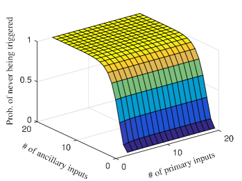
Fig. 12 illustrates the effect of ancillary inputs on triggering a Trojan. The number of patterns that can trigger the Trojan is set to . The number of primary inputs and ancillary inputs is varied from 3 to 20 and from 1 to 20, respectively. The probability that the Trojan is never triggered is 0 when there are few ancillary inputs no matter the number of primary inputs. A Trojan in a reversible circuit can always be triggered in such a situation. However, this probability increases exponentially with the number of ancillary inputs. A small number of ancillary inputs can disable triggering a Trojan with a very high probability. As a result, extra ancillary inputs can protect the host from Trojan even when there are insufficient number of ancillary inputs created during embedding.
VI Experiments
The experiments use the QMDD synthesis approach that takes as input a reversible truth table, outputs its implementation in reversible logic, and reports the cost [23, 36]. Benchmark circuits are taken from revlib [37]. The scrambling technique in Section V is partitioned into several levels, including all ancillary inputs being 0 (), half ancillary inputs being 0 and the other half being 1 (), random ancillary inputs for each primary input pattern (), and adding extra 1 ancillary input ().
To have a fair comparison on the probability of disabling Trojans across different scrambling levels, the study is carried on the Trojans that have only 1 triggering pattern. The Trojans with this assumption always have a minimum probability being detected in the test mode, which is favored by the attacker. Assuming random inputs patterns are applied, we can then calculate the probability of such Trojans being disabled in the functional mode. Since scrambling levels , and have the same number of ancillary inputs, they have the same probability of disabling same Trojans. After adding an extra ancillary input, the probability will be improved. Experimental results of , are shown in TABLE III.
From TABLE III, we can observe that, without adding any extra ancillary inputs, all benchmarks have at least 50% chance of disabling the Trojans that have just 1 triggering pattern. Some benchmarks are even close to 100%. With one more extra ancillary inputs, the probability is always higher. This is great in thwarting Trojans in reversible circuits since the attackers may need to re-evaluate the trade-off between the great risk they will bear by inserting these Trojans and the usefulness of these Trojans.
| Benchmark | Total inputs | constants | Probability of being disabled (%) | |
| Baseline-Lv2 | Lv3 | |||
| decod24_10 | 4 | 2 | 75.0 | 87.5 |
| 4gt12_24 | 5 | 1 | 50.0 | 75.0 |
| decod24_32 | 6 | 3 | 87.5 | 93.8 |
| f2_158 | 7 | 3 | 87.5 | 93.8 |
| rd53_68 | 7 | 2 | 75.0 | 87.5 |
| rd73_69 | 9 | 2 | 75.0 | 87.5 |
| sqn_203 | 9 | 2 | 75.0 | 87.5 |
| squar5_206 | 9 | 4 | 93.8 | 96.9 |
| wim_220 | 9 | 5 | 96.9 | 98.4 |
| dc1_142 | 10 | 6 | 98.4 | 99.2 |
| dist_144 | 10 | 2 | 75.0 | 87.5 |
| root_197 | 10 | 2 | 75.0 | 87.5 |
| clip_124 | 11 | 2 | 75.0 | 87.5 |
| rd84_70 | 11 | 3 | 87.5 | 93.8 |
| sqr6_204 | 12 | 6 | 98.4 | 99.2 |
| cm42a_125 | 13 | 9 | 99.8 | 99.9 |
| dc2_143 | 13 | 5 | 96.9 | 98.4 |
| mlp4_184 | 13 | 5 | 96.9 | 98.4 |
| pm1_192 | 13 | 9 | 99.8 | 99.9 |
| alu2_96 | 14 | 4 | 93.8 | 96.9 |
| alu3_97 | 14 | 4 | 93.8 | 96.9 |
| example2_156 | 14 | 4 | 93.8 | 96.9 |
| inc_170 | 14 | 7 | 99.2 | 99.6 |
| misex1_178 | 14 | 6 | 98.4 | 99.2 |
| sao2_199 | 14 | 4 | 93.8 | 96.9 |
| co14_135 | 15 | 1 | 50.0 | 75.0 |
| dk27_146 | 15 | 6 | 98.4 | 99.2 |
| x2_223 | 16 | 6 | 98.4 | 99.2 |
| t481_208 | 17 | 1 | 50.0 | 75.0 |
| Average | 85.8 | 92.9 | ||
The overhead of all scrambling levels is also evaluated for each benchmark circuit in terms of the number of lines (Line Cost), the number of gates (Gate Cost) and the number of primitive reversible logic gates (1*1, 2*2) required to realize the circuit (Quantum Cost). A Toffoli gate may consist of several primitive reversible logic gates, so the quantum cost is several times larger than the gate cost. The overhead of each scrambling level () is compared against the baseline. For reversible circuits that only have 1 ancillary input, the overhead of is not calculated in Table IV.
It is observed that for the scrambling levels that has no extra ancillary input (-), the line cost is always 0. For the scrambling levels that have extra ancillary input(s) (), the line cost presents, but the relative overhead decreases with the scale of benchmark circuits.
Besides, has maximum average gate cost and quantum cost compared to other scrambling levels. This is because, assigning random ancillary inputs for each input pattern forms a most complex function, which will need more gates to realize it. As a result, for both security- and gate/quantum cost-aware designs, introducing extra ancillary inputs can be a substitution for further improving scrambling levels with less gate/quantum cost while at extra line cost. It is also observed the gate cost and quantum cost increase significantly for some designs. This is partially because the state-of-art synthesis algorithm is still on its early stage where obtaining a valid implementation is still the primary goal.
| Benchmark | Line Cost (%) | Gate Cost (%) | Quantum Cost (%) | ||||||
|---|---|---|---|---|---|---|---|---|---|
| Lv1 | Lv2 | Lv3 | Lv1 | Lv2 | Lv3 | Lv1 | Lv2 | Lv3 | |
| decod24_10 | 0 | 0 | 25 | 44 | 0 | 33.3 | 54 | 1.2 | 88 |
| 4gt12_24 | N/A | 0 | 20 | N/A | 100 | 325 | N/A | 168 | 782 |
| decod24_32 | 0 | 0 | 17 | 20 | 57 | -17 | 19 | 77 | -15 |
| f2_158 | 0 | 0 | 14 | 1.4 | 81 | -35 | 0.6 | 96 | -29 |
| rd53_68 | 0 | 0 | 14 | 31 | 97 | 44 | 30 | 120 | 59 |
| rd73_69 | 0 | 0 | 11 | -15 | 38 | 30 | -16 | 45 | 36 |
| sqn_203 | 0 | 0 | 11 | -0.5 | 55 | 17 | -2 | 54 | 20 |
| squar5_206 | 0 | 0 | 11 | 96 | 344 | 56 | 125 | 496 | 77 |
| wim_220 | 0 | 0 | 11 | 118 | 387 | 81 | 133 | 526 | 89 |
| dc1_142 | 0 | 0 | 10 | 98 | 428 | 141 | 112 | 629 | 189 |
| dist_144 | 0 | 0 | 10 | 28 | 48 | 77 | 29 | 51 | 79 |
| root_197 | 0 | 0 | 10 | 45 | 288 | 72 | 56 | 369 | 86 |
| clip_124 | 0 | 0 | 9 | 235 | 241 | 153 | 277 | 294 | 170 |
| rd84_70 | 0 | 0 | 9 | 15 | 163 | 50 | 14 | 189 | 62 |
| sqr6_204 | 0 | 0 | 8 | 220 | 1356 | 166 | 538 | 3698 | 353 |
| cm42a_125 | 0 | 0 | 8 | 44 | 953 | 444 | 116 | 3347 | 1018 |
| dc2_143 | 0 | 0 | 8 | 192 | 5257 | 529 | 457 | 20691 | 2129 |
| mlp4_184 | 0 | 0 | 8 | 145 | 483 | -3 | 159 | 620 | -1.3 |
| pm1_192 | 0 | 0 | 8 | 44 | 1109 | 371 | 116 | 3495 | 723 |
| alu2_96 | 0 | 0 | 7 | 43 | 1977 | 97 | 49 | 3124 | 177 |
| alu3_97 | 0 | 0 | 7 | 115 | 15922 | 276 | 168 | 32454 | 618 |
| example2_156 | 0 | 0 | 7 | 43 | 1847 | 97 | 49 | 2913 | 177 |
| inc_170 | 0 | 0 | 7 | 68 | 8480 | 761 | 103 | 33166 | 2481 |
| misex1_178 | 0 | 0 | 7 | 526 | 9725 | 817 | 1122 | 28870 | 1886 |
| sao2_199 | 0 | 0 | 7 | 36 | 8054 | 655 | 18 | 17197 | 1439 |
| dk27_146 | 0 | 0 | 7 | 99 | 3854 | 240 | 124 | 5149 | 320 |
| x2_223 | 0 | 0 | 6 | 127 | 5169 | -19 | 124 | 5472 | -18 |
| t481_208 | N/A | 0 | 4 | N/A | 3156 | 716 | N/A | 8014 | 1363 |
| AVERAGE | 0 | 0 | 10 | 91 | 2488 | 221 | 148 | 6118 | 513 |
VII Conclusion and Future Work
As the circuit designer has a good knowledge of all gates in reversible circuits, any missing control/gate fault caused by imperfect fabrication is easy to detect through test pattern generation. Compared to existing fault models, deliberately designed and inserted Trojans are sophisticated and unpredictable, and hence more difficult to detect and counter.
Our investigation shows that, by exploiting the inherent reversibility of these circuits, a set of predefined test patterns can trigger (and hence detect) any Trojan up-to 4 gates in size inserted at any position in the host circuit. The attacker is forced to insert symmetric Trojans that have 5 or more gates. We propose to scramble inputs to thwart such Trojans in the functional mode of host circuits. The inputs to the circuit are scrambled by assigning secret values to the ancillary inputs and introducing extra ancillary inputs. Without knowing these secret values and extra ancillary inputs, a Trojan designer has to risk an increased chance that the Trojan may never be triggered during circuit functional mode, which invalidates his original motivation.
VII-A Discussion and Future Work
It is observed in the experiments that the overhead varies significantly for benchmark circuits within the same scrambling level or for the same circuits at different scrambling levels. That is, the increase of overhead (in terms of gate cost or quantum cost) from to are not in a fixed relation. This is because, the current synthesis approaches do not take the scrambling technique into consideration. Thus developing an overhead- and security-aware synthesis approach will be an important future work.
Besides, this work only considers hardware Trojans that consist of consecutive gates. However, an attacker may design a Trojan that has several distributed parts and each part may consist of multiple gates. The investigation of this kind of Trojan in reversible circuits will also be a part of future work.
References
- [1] Quantum Computation and Quantum Information. New York, NY, USA: Cambridge University Press, 2000.
- [2] A. Barenco, C. H. Bennett, R. Cleve, D. DiVinchenzo, N. Margolus, P. Shor, T. Sleator, J. Smolin, and H. Weinfurter, “Elementary gates for quantum computation,” The American Physical Society, vol. 52, pp. 3457–3467, 1995.
- [3] P. Niemann, S. Basu, A. Chakrabarti, N. K. Jha, and R. Wille, “Synthesis of quantum circuits for dedicated physical machine descriptions,” 2015, pp. 248–264.
- [4] L. K. Grover, “A fast quantum mechanical algorithm for database search,” in Theory of computing, 1996, pp. 212–219.
- [5] P. W. Shor, “Algorithms for quantum computation: discrete logarithms and factoring,” Foundations of Computer Science, pp. 124–134, 1994.
- [6] M. Saeedi, M. Arabzadeh, M. S. Zamani, and M. Sedighi, “Block-based quantum-logic synthesis,” vol. 11, no. 3&4, pp. 262–277, 2011.
- [7] R. Drechsler and R. Wille, “From truth tables to programming languages: Progress in the design of reversible circuits,” in International Symposium on Multiple-Valued Logic, ISMVL, 2011, pp. 78–85. [Online]. Available: http://dx.doi.org/10.1109/ISMVL.2011.40
- [8] D. Große, R. Wille, G. W. Dueck, and R. Drechsler, “Exact synthesis of elementary quantum gate circuits,” vol. 15, no. 4, pp. 270–275, 2009.
- [9] R. Landauer, “Irreversibility and heat generation in the computing process,” IBM Journal of Research and Development, vol. 5, no. 3, pp. 183–191, 1961.
- [10] C. H. Bennett, “Logical reversibility of computation,” IBM J. Res. Dev, vol. 17, no. 6, pp. 525–532, 1973.
- [11] A. Berut, A. Arakelyan, A. Petrosyan, S. Ciliberto, R. Dillenschneider, and E. Lutz, “Experimental verification of Landauer’s principle linking information and thermodynamics,” Nature, vol. 483, pp. 187–189, 2012.
- [12] W. C. Athas and L. J. Svensson, “Reversible logic issues in adiabatic cmos,” in Physics and Computation, 1994. PhysComp ’94, Proceedings., Workshop on, Nov 1994, pp. 111–118.
- [13] L. G. Amarù, P. Gaillardon, R. Wille, and G. D. Micheli, “Exploiting inherent characteristics of reversible circuits for faster combinational equivalence checking,” 2016, pp. 175–180. [Online]. Available: http://ieeexplore.ieee.org/xpl/freeabs_all.jsp?arnumber=7459300
- [14] R. Cuykendall and D. R. Andersen, “Reversible optical computing circuits,” Opt. Lett., vol. 12, no. 7, pp. 542–544, Jul 1987. [Online]. Available: http://ol.osa.org/abstract.cfm?URI=ol-12-7-542
- [15] S. Roy, P. Sethi, J. Topolancik, and F. Vollmer, “All-optical reversible logic gates with optically controlled bacteriorhodopsin protein-coated microresonators,” Advances in Optical Technologies, vol. 2012, 2011.
- [16] S. M. R. Taha, “Fundamentals of reversible logic,” in Reversible Logic Synthesis Methodologies with Application to Quantum Computing. Springer, 2016, pp. 7–16.
- [17] V. V. Shende, A. K. Prasad, I. L. Markov, and J. P. Hayes, “Reversible logic circuit synthesis,” 2002, pp. 353–360.
- [18] D. M. Miller, D. Maslov, and G. W. Dueck, “A transformation based algorithm for reversible logic synthesis,” in Proc. of the 40th Design Automation Conference, DAC 2003. ACM, 2003, pp. 318–323.
- [19] G. Yang, X. Song, W. N. N. Hung, and M. A. Perkowski, “Fast synthesis of exact minimal reversible circuits using group theory,” 2005, pp. 1002–1005.
- [20] P. Gupta, A. Agrawal, and N. K. Jha, “An algorithm for synthesis of reversible logic circuits,” vol. 25, no. 11, pp. 2317–2330, 2006.
- [21] R. Wille and R. Drechsler, “Bdd-based synthesis of reversible logic for large functions,” in Proceedings of the 46th Annual Design Automation Conference. ACM, 2009, pp. 270–275.
- [22] M. Soeken, R. Wille, C. Hilken, N. Przigoda, and R. Drechsler, “Synthesis of reversible circuits with minimal lines for large functions,” 2012, pp. 85–92.
- [23] A. Zulehner and R. Wille, “Make it reversible: Efficient embedding of non-reversible functions,” 2017.
- [24] Y. Jin, N. Kupp, and Y. Makris, “Experiences in hardware trojan design and implementation,” in HOST’09.
- [25] M. Tehranipoor and F. Koushanfar, “A survey of hardware trojan taxonomy and detection,” Design & Test of Computers, IEEE, 2010.
- [26] K. Xiao and M. Tehranipoor, “Bisa: Built-in self-authentication for preventing hardware trojan insertion,” in Hardware-Oriented Security and Trust (HOST), 2013 IEEE International Symposium on. IEEE, 2013, pp. 45–50.
- [27] X. Cui, K. Ma, L. Shi, and K. Wu, “High-level synthesis for run-time hardware trojan detection and recovery,” in Design Automation Conference (DAC), 2014 51st ACM/EDAC/IEEE. IEEE, 2014, pp. 1–6.
- [28] H. Salmani, M. Tehranipoor, and J. Plusquellic, “A novel technique for improving hardware trojan detection and reducing trojan activation time,” VLSI Systems, IEEE Transactions on, vol. 20, no. 1, pp. 112–125, Jan 2012.
- [29] X. Wang, H. Salmani, M. Tehranipoor, and J. Plusquellic, “Hardware trojan detection and isolation using current integration and localized current analysis,” in DFTVS’08, pp. 87–95.
- [30] Y. Jin and Y. Makris, “Hardware trojan detection using path delay fingerprint,” in HOST’08. IEEE International Workshop on, pp. 51–57.
- [31] H. Salmani and M. M. Tehranipoor, “Vulnerability analysis of a circuit layout to hardware trojan insertion,” IEEE Transactions on Information Forensics and Security, vol. 11, no. 6, pp. 1214–1225, June 2016.
- [32] K. N. Patel, J. P. Hayes, and I. L. Markov, “Fault testing for reversible circuits,” IEEE Transactions on Computer-Aided Design of Integrated Circuits and Systems, vol. 23, no. 8, pp. 1220–1230, 2004.
- [33] K. Ramasamy, R. Tagare, E. Perkins, and M. Perkowski, “Fault localization in reversible circuits is easier than for classical circuits,” 2004.
- [34] J. P. Hayes, I. Polian, and B. Becker, “Testing for missing-gate faults in reversible circuits,” in Test Symposium, 2004. 13th Asian. IEEE, 2004, pp. 100–105.
- [35] R. Wille, H. Zhang, and R. Drechsler, “Atpg for reversible circuits using simulation, boolean satisfiability, and pseudo boolean optimization,” in VLSI (ISVLSI), 2011 IEEE Computer Society Annual Symposium on. IEEE, 2011, pp. 120–125.
- [36] M. Soeken, R. Wille, C. Hilken, N. Przigoda, and R. Drechsler, “Synthesis of reversible circuits with minimal lines for large functions,” in 17th Asia and South Pacific Design Automation Conference, Jan 2012, pp. 85–92.
- [37] R. Wille, D. Große, L. Teuber, G. W. Dueck, and R. Drechsler, “RevLib: an online resource for reversible functions and reversible circuits,” 2008, pp. 220–225, RevLib is available at http://www.revlib.org.