Calibration and irradiation study of the BGO background monitor for the BEAST II experiment
Abstract
Beam commissioning of the SuperKEKB collider began in 2016. The Beam Exorcism for A STable experiment II (BEAST II) project is particularly designed to measure the beam backgrounds around the interaction point of the SuperKEKB collider for the Belle II experiment. We develop a system using bismuth germanium oxide (BGO) crystals with optical fibers connecting to a multianode photomultiplier tube (MAPMT) and a field-programmable gate array (FPGA) embedded readout board for monitoring the real-time beam backgrounds in BEAST II. The overall radiation sensitivity of this system is estimated to be Gy/ADU (analog-to-digital unit) with the standard 10 m fibers for transmission and the MAPMT operating at 700 V. Our -ray irradiation study of the BGO system shows that the exposure of BGO crystals to 60Co -ray doses of 1 krad has led to immediate light output reductions of 25–40%, and the light outputs further drop by 30–45% after the crystals receive doses of 2–4 krad. Our findings agree with those of the previous studies on the radiation hard (RH) BGO crystals grown by the low thermal gradient Czochralski (LTG Cz) technology. The absolute dose from the BGO system is also consistent with the simulation, and is estimated to be about 1.18 times the equivalent dose. These results prove that the BGO system is able to monitor the background dose rate in real time under extreme high radiation conditions. This study concludes that the BGO system is reliable for the beam background study in BEAST II.
1 Introduction
The SuperKEKB collider [1] at KEK, Japan is designed to supply high-luminosity collisions for the Belle II experiment [2, 3] (the successor to the Belle experiment [4]). Its first beam circulation in 2016 brings forth a new era of accelerator operation. The Beam Exorcism for A Stable experiment II (BEAST II) project is dedicated to study beam-induced backgrounds prior to the Belle II full installation and commissioning. This is essential for beam commissioning and the protection of the real Belle II detector from unexpected high radiation. The HEP group of National Taiwan University (NTUHEP) has developed a compact system for monitoring the real-time beam backgrounds in BEAST II. The measured beam backgrounds are centralized in the BEAST II DAQ (data acquisition) system and fed back to the SuperKEKB control center.
The BGO system adopts bismuth germanate Bi4Ge3O12 (BGO) crystal sensors for the detection of charged particles and photon background. BGO is a well-known material extensively used as scintillators. Since the scintillation property of BGO was discovered [5], its fine energy resolution, high density, large refractive index, and non-hygroscopic nature have promoted its widely application in high energy physics, nuclear physics, positron emission tomography (PET), and many other fields. However, the high sensitivity to radiation damage of BGO crystal upon irradiation has limited its use in high energy applications. Therefore, several works have been conducted to study the radiation damage to BGO crystals. Early studies by Kobayashi et al. (1983) [6] reported that the extent to which a crystal is damaged is related to its impurity concentration. Wei et al. (1990) discovered that the radiation resistance of BGO crystals is improved by europium doping [7]. Yanovsky et al. (1991), on the other hand, revealed that BGO crystals from certain manufacturers show very high radiation hardness even up to 100 Mrad of irradiation and without any photochromic effect [8]. Zhu et al. (1995) also showed that doped BGO crystals could suffer damage by radiation even at 1 krad [9]. Georgii et al. (1998) further performed systematic radiation damage studies on BGO crystals grown by different manufacturers [10].
The low thermal gradient Czochralski (LTG Cz) technique, developed by Nikolaev Institute of Inorganic Chemistry (NIIC) of the Siberian Branch of the Russian Academy of Sciences, is commonly used for growing BGO crystals [11]. Compared with the conventional Czochralski (Cz) technique and the Bridgman method, the LTG Cz technique reduces the temperature gradients, and the solidification front becomes fully faceted. It improves the quality of the crystals. In addition, under the LTG Cz condition, the sensitive properties of crystals to the growth mechanism allow one to control the radiation hardness of BGO crystals by choosing appropriate growth conditions. As a result, radiation hard (RH) crystals are grown. The LTG Cz technology was developed in the NIIC as a routine way to grow nearly perfect undoped RH BGO crystals.
The first large scale application of the RH BGO crystals grown by the LTG Cz technology was the extreme forward calorimeter (EFC) [12] of the Belle detector at KEK B-factory. Our group has constructed this calorimeter to improve coverage of small angles around the beam pipe of the Belle detector, and has surveyed the effects of radiation damage and recovery of undoped RH BGO crystals [13, 14, 15, 16]. The results revealed that the BGO crystals produced using the same LTG Cz growth technique show two distinct types of behavior under irradiation and relaxation. These crystals from mass production [13] (the EFC crystals) are less radiation-hard than the crystals produced in small quantity (the sample crystals) [14, 15, 16]. The former also show considerably slower self-recovery compared to the latter. Similar studies have also been carried out by NIIC [17, 18, 19], and the results also revealed that the BGO crystals grown by the same LTG Cz technology exhibit two distinct types of characteristics. The crystals termed as L-type show weak monotonous degradation of light output upon irradiation and fast relaxation. They remain colorless even after receiving doses of several Mrad. The crystals termed as N-type show strong abrupt degradation of light output upon irradiation and slow relaxation. They become yellow tinted after receiving 1 krad -radiation doses. These findings correspond with the results reported by our group. However, the reasons for the distinct features of the BGO crystals grown by the same LTG Cz technique are not clear yet. Although a considerable difference in electrical self-conductivity is discovered for L- and N-type crystals, there is no noticeable difference in the impurity content between the two types of crystals.
We reuse the scintillating BGO crystals from EFC, and apply them as the sensors of the BGO detector system. We define the radiation sensitivity for one channel of the detector as the calibrated value for the ionizing radiation dose of the BGO crystal normalized to one ADU (analog-to-digital unit) count. In order to determine the radiation sensitivities of the BGO system, the system was first calibrated by a LED source to determine the gain factors of the multianode photomultiplier tube (MAPMT) in units of ADU per photoelectron (p.e.). The p.e yield (p.e./GeV; defined as ) of this system is then determined based on the comparison between the minimum ionizing cosmic ray data and the results of a Geant4 simulation. A special test with the proposed configuration for BEAST II was conducted at the Institute of Nuclear Energy Research (INER), Longtan, Taiwan by a strong 60Co irradiation facility to examine the performance of the system. The results obtained from the BGO system are compared with those obtained from dosimeters and from a Geant4 simulation, respectively.
In this work, we report the design of our system, the calibration procedures, and the results of the irradiation study. The results of the irradiation study are expected to agree with the those of the previous studies performed on the RH BGO crystals grown by the LTG Cz technology. This can demonstrate the success of the BGO detector system and ensure that the data provided by our system for BEAST II are reliable.
2 BGO detector system
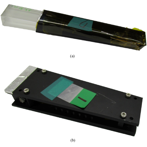
We choose BGO as the electromagnetic shower medium for beam-induced radiation, as shown in figure 1 and figure 2. The dimension of each BGO crystal is about cm3 and has a mass of approximately 0.3135 kg. Each BGO crystal is wrapped with a 100 m thick Teflon sheet and a 25 m thick aluminized Mylar sheet to obtain the maximum light-collection efficiency. Some supporting structures made of nonmagnetic materials are designed to protect the crystals.
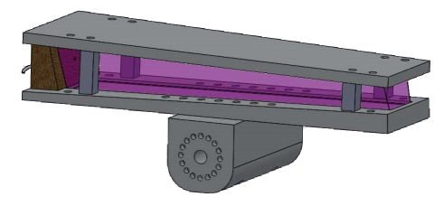
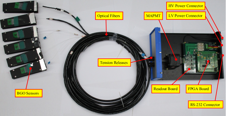
The layout and the schematic of the detector are shown in figure 3 and figure 4, respectively. The BGO system can at most operate with eight BGO sensors. To simplify the design and avoid radiation damage to the electronics, there are no active components on the side of the BGO crystals. The signal from each BGO crystal is conducted to a Hamamatsu H7546 MAPMT via one 10 m Eska SK-40 plastic fiber (1 mm in diameter). A MAPMT mask points each fiber to the center of the corresponding MAPMT pixel. Some light-tight treatments are applied to the fibers and their connections to prevent leakage of light from the environment. The MAPMT, which has a spectral range of 300–650 nm, converts the scintillation light to charge signals. The charge signals from the MAPMT are connected to the readout electronics system. The readout system and the MAPMT are encased in a electrically grounded DAQ box for portability and electromagnetic noise shielding.
The readout system consists of two parts: an eight-channel readout board and a Xilinx 3A/3AN field-programmable gate array (FPGA) board. The FPGA is plugged on top of the readout board, and the firmware developed at Xilinx ISE (Integrated Synthesis Environment) is written by VHDL (VHSIC hardware description language). The readout board inherits the design from the NuTel experiment [20] with some modifications to improve its noise immunity and performance of shaping signals. Each channel of the readout board consists of a preamplifier circuit and a 10-bit pipeline ADC (analog-to-digital converter) chip. The preamplifier reconverts the analog charge signal to analog voltage signal by shaping the pulses through the RC circuit with a 187 ns shaping time, and then the following ADC digitizes the analog voltage signal. With the specific 187 ns shaping time, the input pulse height will drop by about 1/8 after one clock (25 ns) if there are no new input changes. The excess of that will be regarded as the input charges during that clock. Hence. the input charges are calculated by using the following algorithm:
| (2.1a) | ||||
| (2.1b) |
where is the digital signal in the FPGA (in ADUs), is the accumulated input charges in the increment of the 25 ns clock period (in ADUs). After converting the pulse heights to the input charges, the FPGA delivers the acquired data for calculating the accumulated radiation doses to the PCs via a RS-232 serial cable at a data rate of 65.91 Hz without dead time. The computer program processes the raw data and checks the validity. The processed data include the timestamps, the accumulated radiation doses, the severity of ADC overflow, and the checksums. The computer program displays the background conditions on the screen in real time, and stores the processed data on the disk.

3 Calibration methods
3.1 Calibration of gains
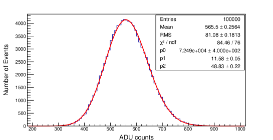
A LED calibration procedure was used to evaluate the gain factors of the MAPMT. We shone light pulses from a 450 nm blue-light LED onto each MAPMT pixel. The intensity of the blue light pulses can be adjusted by setting the input voltage of the LED. The number of p.e. induced by each incident light pulse in the cathode follows a Poisson distribution [21]:
| (3.1) |
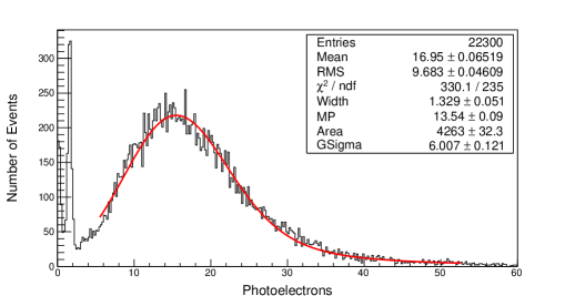
where is the probability of having photoelectrons, is the number of charges (in units of ADUs), is the number of p.e., and is the gain factor (in units of ADU/p.e.). The obtained charge spectra are fitted with eq. 3.1, as shown in figure 5.
3.2 Calibration of photoelectron yield
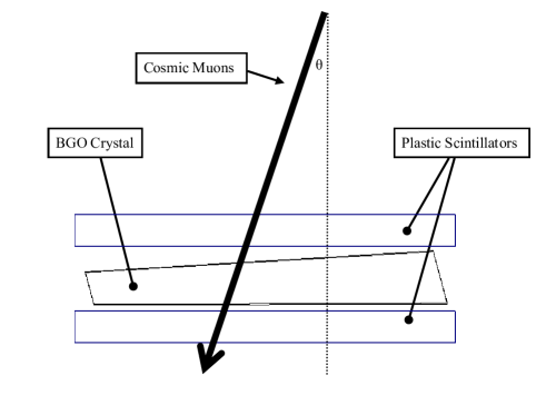
of this system is obtained based on the comparison between the minimum ionizing particles (MIPs) data and the results of the simulation. The schematic of the trigger system for cosmic muon MIPs is shown in figure 6. A PMT was coupled to a BGO crystal through fifty 10-cm Eska SK-40 fibers, and the BGO crystal was sandwiched between two horizontal plastic scintillators. The trigger algorithm was set to ensure that the deposited energy of the BGO crystal and that of each plastic scintillator are larger than the threshold energy—the cosmic-ray muon should hit the BGO crystal and the two scintillators. In the simulation, the energy of each cosmic-ray muon was set at 10 GeV, and the rate of which was proportional to , where is the incident angle deviated from the cosmic rays. The spectra obtained are fitted with Landau convoluted with Gaussian. is then determined by comparing the position of the two MIP peaks:
| (3.2) |
where
-
•
is the most probable value of the energy deposition spectrum of cosmic muon MIPs obtained from the BGO system.
-
•
is the most probable value of the energy deposition spectrum of cosmic muon MIPs obtained from the simulation.
-
•
is the quantum efficiency of the MAPMT with respect to that of the PMT of this calibration.
-
•
is the number of fibers of the trigger system.
To determine , we designed a special test. We shone light pulses with the same amount of energy onto the MAPMT and the PMT. is determined by the following formula:
| (3.3) |
where is the number of p.e. induced by each incident light pulse onto the MAPMT pixel; is the number of p.e. induced by each incident light pulse onto the PMT pixel; is the photon-receiving area of the PMT; is the photon-receiving area of the MAPMT. To examine the alignment of the MAPMT mask, we measured with and without the MAPMT mask, respectively.
4 Irradiation study
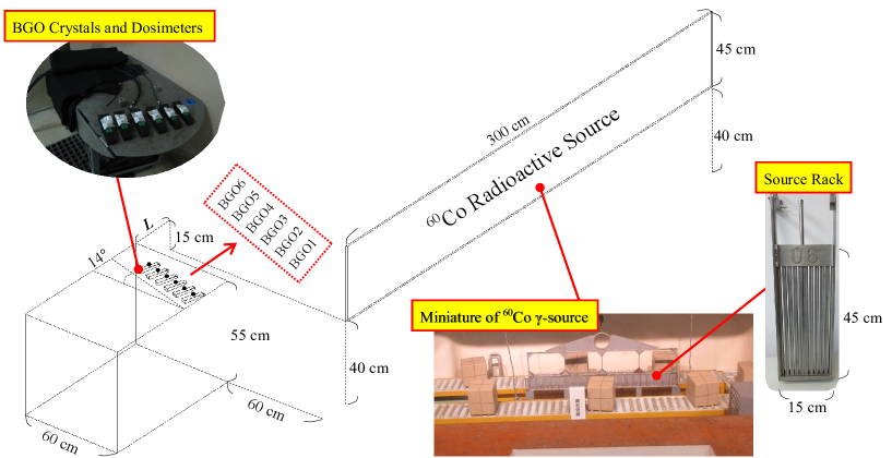
Only six of the eight BGO crystals were mounted on the BGO system for the irradiation test because the other two had been sent to the University of Hawaii for further tests. Some commercial alanine dosimeters (AWM230 from A. Wieser Messtechnik, batch 00303/M5) prepared by INER were placed on top of each BGO crystal. The irradiation source was 60Co with a dimension of about cm3. The activity of the source was around Bq. Schematic of the experimental setup for the -ray irradiation is shown in figure 7.
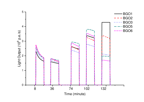
We conducted five irradiation steps with different irradiation conditions. In this study, the absolute dose is defined as the dose absorbed by the sample, and the equivalent dose is defined as the amount of dose that would have been absorbed by water if placed at the same position. The BGO system monitored the light output (p.e. rate) of each crystal in real time to determine to the absolute dose; the dosimeters measured the equivalent dose for each crystal. Besides, the Geant4 simulation provided simulated absolute doses for the whole irradiation procedure.
In each irradiation step, the source would quickly rise from water until it reached the highest point, and then remained stable for 15 minutes. In the first step, a bare BGO crystal was put near the source to examine the light-tightness of the system. The scintillation light from the bare crystal functioned as a light pollution source from the environment. The bare crystal glowed brightly during the irradiation, and appeared to be yellow tilted and warmer after removal. In the last step, the table was rotated 90∘ counterclockwise to have the crystals irradiated transversely. The details of each step are given in table 1. We first studied the dependence of light outputs on the elapsed time and the absorbed dose, respectively. Then the absolute doses in each step measured by the BGO system were compared with those obtained from dosimeters and from the simulation, respectively. The absolute doses from the BGO system are obtained based on the following assumptions:
-
1.
The dose rate in each step is a step function with a duration of exactly 15 minutes corresponding to the stable periods of the source.
-
2.
The degradation of light output in each step is accumulated to the next step without recovery.
The whole irradiation procedure lasted for 2.5 h, and the total accumulated dose of each crystal was about 4.5 krad. The dosimeters were 10 mm in length and 4.8 mm in diameter, and their suitable range of dose measurement was 1–100 Gy, which meets our dose measurement requirements. The irradiation test was performed in a darkroom, and the system was covered with block cloth to strengthen the light-tightness. A pedestal run was carried out to check the noise level from electronics and environmental radiation prior to the test.
Although the experimental setup was covered with block cloth, the connections between the fibers and the crystals were not glued with silicon, allowing in-situ adjustments. Inevitably, the scintillation light of the bare crystal in the first step might contribute some extra light outputs to the system if there was light leakage. The light outputs due to the bare crystal were removed carefully when we calculated the absolute doses.
| Step | Start time (minutes) | (m) | Note |
|---|---|---|---|
| 1 | 8 | 3.0 | Light-tightness test |
| 2 | 36 | 3.0 | |
| 3 | 74 | 2.0 | |
| 4 | 102 | 1.5 | |
| 5 | 132 | 2.0 | Irradiated transversely |
5 Results and discussion
5.1 Calibration
5.1.1 Gain factors of the MAPMT
The gain factors of the MAPMT operating at 700 V are summarized in table 2. The results agree with the values in the data sheet.
| BGO channel | Gain (ADU/p.e.) |
|---|---|
| CH1 | |
| CH2 | |
| CH3 | |
| CH4 | |
| CH5 | |
| CH6 | |
| CH7 | |
| CH8 |
5.1.2 Photoelectron yield
We assume that the alignment of the MAPMT mask is perfect enough to centralize and restrict the light to the corresponding pixels without significant loss. The results of the measurements of with and without the MAPMT mask are listed below:
- With the MAPMT mask:
-
With optical fibers for transmission. One end of the fiber was connected to the PMT pixel with a special fixture. and both were 1 mm2, the cross section area of the fibers. is determined to be .
- Without the MAPMT mask:
-
Without optical fibers for transmission. was reduced to 3.799 mm2 by a collimator; was 4 mm2, the pixel area of the MAPMT. is determined to be .
There is no significant difference between the values of measured under the two different conditions, justifying the previous assumption. The alignment of the MAPMT mask is very good. is then determined to be .
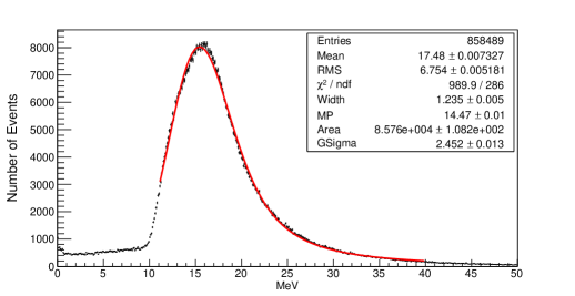
Figure 8 and figure 9 show the energy deposition spectra of cosmic muon MIPs obtained from the BGO system and the simulation, respectively, where is p.e. and is MeV. is consistent with the 9 MeV/cm) of MIPs passing through BGO. Therefore, is determined to be p.e./GeV with ideally zero meter fibers for transmission. However, with the standard 10 m fibers for transmission, the signals would attenuate to , according to our measurements. As a results, is determined to be p.e./GeV. with the standard 10 m fibers for transmission.
5.1.3 Radiation sensitivity
The radiation sensitivities of the BGO detector system are given in table 3. The overall radiation sensitivity of this system is estimated to be Gy/ADU with the standard 10 m fibers for transmission and the MAPMT operating at 700 V.
| BGO channel | Sensitivity (Gy/ADU) |
|---|---|
| CH1 | |
| CH2 | |
| CH3 | |
| CH4 | |
| CH5 | |
| CH6 | |
| CH7 | |
| CH8 |
5.2 Irradiation study
The pedestal run before the irradiation test showed that the noise from the electronics and the environmental radiation can be negligible. Because of some optical-path problems, the response of BGO-4 is only about one fourth of the other signals. Hence, BGO-4 is excluded from our analyses.
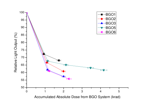
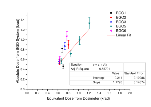
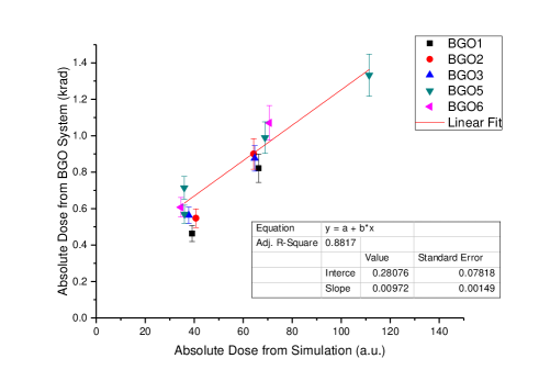
The results of the irradiation are relatively monotonous decreases of the light outputs with the elapsed time. The kinetics of the light outputs under irradiation is shown in figure 10. The light outputs increase as the decrease of , the distance between the source and the BGO crystals. As the crystals are irradiated transversely, the light outputs severely saturate for BGO-1, and decrease from BGO-1 to BGO-6 gradually. The extra light outputs due to the bare crystal in the first step are less than 3%. The overflow data and the extra light outputs are excluded from our following analyses. The typical change of the relative light output, depending on the absorbed -radiation dose within the interval of 1–5 krad is shown in figure 11. The light outputs drop abruptly at 1 krad doses, reaching values close to the saturation. The absolute dose measured by the BGO system as a function of the dose from the dosimeters and from the simulation are shown in 12 and figure 13, respectively. The linearity appears very good.
We studied the dependence of light outputs on the elapsed time and the absorbed dose, respectively, and compared the absolute doses from the BGO system with those obtained from the dosimeters and from the simulation, respectively. The results reveal that the exposure of BGO crystals to 60Co -ray doses of 1 krad has led to immediate light output reductions of 25–40%, and the light outputs further drop by 30–45% after the crystals receive doses of 2–4 krad. The BGO crystals appear to receive more doses when irradiated transversely. A salient -ray shielding ability of the BGO crystals is also observed. The absolute dose from the BGO system is consistent with the simulation, and is estimated to be about 1.18 times the equivalent dose.
Our findings agree with those of the survey of the scintillation properties of the BGO crystals for EFC at Belle [13], which stated that the crystals show the light yield drops about 25–50% after receiving 1 krad dose and remain stable afterwards. Our results also correspond with the reported features of the N-type BGO crystals grown by the LTG Cz technology [17, 18, 19], which revealed that the N-type crystals show strong abrupt degradation to 35–50% upon irradiation and slow relaxation, and may become yellow tinted after receiving 1 krad -radiation doses.
The irradiation study proves that the BGO system is able to monitor the background dose rate in real time under extreme high radiation conditions. The results of the irradiation study also agree with the those of the previous studies performed on the RH BGO crystals grown by the LTG Cz technology. This demonstrates the success of the BGO detector system, and ensure that the data provided by this system for BEAST II are reliable.
6 Conclusions
The BGO background monitor designed by the NTUHEP group was calibrated and tested. The overall radiation sensitivity of this system is estimated to be Gy/ADU with the standard 10 m fibers for transmission and the MAPMT operating at 700 V.
The results of the irradiation study reveal that the exposure of BGO crystals to 60Co -ray doses of 1 krad has led to immediate light output reductions of 25–40%, and the light outputs further drop by 30–45% after the crystals receive doses of 2–4 krad. Our findings agree with those of the previous studies on the RH BGO crystals grown by the LTG Cz technology [13, 17, 18, 19]. The absolute dose from the BGO system is also consistent with the simulation, and is estimated to be about 1.18 times the equivalent dose. These results prove that the BGO system is able to monitor the background dose rate in real time under extreme high radiation conditions. This study concludes that the BGO system is reliable for the beam background study in BEAST II.
Acknowledgments
We are very grateful for the help from the INER people during the irradiation test. This work is supported by the Ministry of Science and Technology (Taiwan) under the grant MOST 103-2112-M-002-017-MY3.
References
- [1] Y. Ohnishi et al., Accelerator design at SuperKEKB, Prog. Theor. Exp. Phys. 2013 (2013) .
- [2] T. Abe et al., Belle II technical design report, arXiv preprint arXiv:1011.0352 (2010) .
- [3] T. Konno, Status and prospects of the Belle II experiment, 2nd International Workshop on Theoretical and Computational Physics: Modern Methods and Latest Results in Particle Physics, Nuclear Physics and Astrophysics, IWTCP 2014 and the 39th National Conference on Theoretical Physics, NCTP 2014 627 (2015) .
- [4] A. Abashian et al., The Belle detector, Nucl Instrum Meth A 479 (2002) 117–232.
- [5] M. J. Weber and R. R. Monchamp, Luminescence of Bi4Ge3O12: Spectral and decay properties, J. Appl. Phys. 44 (1973) 5495–5499.
- [6] M. Kobayashi et al., Radiation damage of BGO crystals due to low energy rays, high energy protons and fast neutrons, Nucl Instrum Methods 206 (1983) 107–117.
- [7] Z. Y. Wei et al., Radiation resistance and fluorescence of europium doped BGO crystals, Nucl Instrum Meth A 297 (1990) 163–168.
- [8] V. V. Yanovsky et al., BGO crystals - radiation hard scintillators, Nucl Instrum Meth A 309 (1991) 596–597.
- [9] R. y. Zhu et al., Scintillating crystals in a radiation environment, Nuclear Physics B (Proceedings Supplements) 44 (1995) 547–556.
- [10] R. Georgii et al., Influence of radiation damage on BGO scintillation properties, Nucl Instrum Meth A 413 (1998) 50–58.
- [11] Y. V. Vasiliev et al., BGO crystals grown by a low thermal gradient Czochralski technique, Nucl Instrum Meth A 379 (1996) 533–535.
- [12] M. Z. Wang et al., Beam test of the BELLE extreme forward calorimeter at KEK, Nucl Instrum Meth A 455 (2000) 319–323.
- [13] R. Akhmetshin et al., Survey of the properties of BGO crystals for the Extreme Forward Calorimeter at BELLE, Nucl Instrum Meth A 455 (2000) 324–328.
- [14] S. K. Sahu et al., Radiation hardness of undoped BGO crystals, Nucl Instrum Meth A 388 (1997) 144–148.
- [15] K. C. Peng et al., Performance of undoped BGO crystals under extremely high dose conditions, Nucl Instrum Meth A 427 (1999) 524–527.
- [16] K. C. Peng et al., Low-dose radiation damage and recovery of undoped BGO crystals, Nucl Instrum Meth A 452 (2000) 252–255.
- [17] Y. A. Borovlev et al., Progress in growth of large sized BGO crystals by the low-thermal-gradient Czochralski technique, J. Cryst. Growth 229 (2001) 305–311.
- [18] V. A. Gusev et al., Features of radiation damage of BGO crystals grown by the low-thermal-gradient Czochralski technique, Nucl Instrum Meth A 460 (2001) 457–464.
- [19] V. A. Gusev et al., The effect of radiation damage on optical and scintillation properties of BGO crystals grown by the LTG Cz technique, Proceedings of the 6th International Conference on Inorganic (SCINT 2001) 486 (2002) 350–354.
- [20] Y. S. Velikzhanin et al., Design of a general purpose data collection module for the NuTel telescope, Nucl Instrum Meth A 552 (2005) 477–488.
- [21] D. L. Fried, Noise in photoemission current, Applied Optics 4 (1965) 79–80.