Strong anisotropy effect in iron-based superconductor CaFe0.882Co0.118AsF
Abstract
The anisotropy of the Fe-based superconductors is much smaller than that of the cuprates and the theoretical calculations. A credible understanding for this experimental fact is still lacking up to now. Here we experimentally study the magnetic-field-angle dependence of electronic resistivity in the superconducting phase of iron-based superconductor CaFe0.882Co0.118AsF, and find the strongest anisotropy effect of the upper critical field among the iron-based superconductors based on the framework of Ginzburg-Landau theory. The evidences of energy band structure and charge density distribution from electronic structure calculations demonstrate that the observed strong anisotropic effect mainly comes from the strong ionic bonding in between the ions of Ca2+ and F-, which weakens the interlayer coupling between the layers of FeAs and CaF. This finding provides a significant insight into the nature of experimentally observed strong anisotropic effect of electronic resistivity, and also paves an avenue to design exotic two dimensional artificial unconventional superconductors in future.
Keywords: CaFe0.882Co0.118AsF, Fe-based Superconductors, Anisotropy
I introduction
Since the discovery of superconductivity of 26 K in fluorine doped quaternary compound LaFeAsO, LaFeAsO the studies of the mechanism of iron-based superconductors (FeSCs) have evoked enormous interests across the community of superconductivity and material science. Huge experiments have revealed that the iron-based superconductors belong to a family of an unconventional pairing mechanism within layered FeAs(Se). The information of upper critical field and its anisotropy in superconductivity can be used as a fingerprint to understand the unconventional superconducting mechanism and to promote the practical applications . gamma-1 ; gamma-2 ; 8 In addition, bidimensionality, which is represented by a rather high anisotropy between the -plane and direction, is believed to be a very important factor for the occurrence of strong correlation physics and even high- superconductivity CDW1 ; CDW2 ; SDW1 ; Cuprates ; Chu . Generally speaking, the anisotropy parameter of the FeSCs was found to be much smaller than that of the cuprates and the theoretical calculations. NdFeAsO0.82F0.18 ; 10-4-8 ; 10 ; 11 ; 12 ; 13 ; Singh1 ; Cuprates Although the Pauli-limit effects have been taken into account in well understanding the low temperature behaviors of , Pauli-limiting1 ; Pauli-limiting2 ; Pauli-limiting3 the nature of such small value of anisotropy parameter of FeScs remains unclear in the vicinity of superconducting (SC) transition temperature . Interestingly, it has been found that the values of is linearly proportional to the distance of adjacent conducting layers for both the cuprates supeconductors and FeSCs, Cuprates ; 10-4-8 which is understandable since a thicker insulating block layer weakens the interlayer hybridization, as a result the anisotropy will be enhanced. Quantitatively, the value of FeSCs has a magnitude typically two orders lower than that of cuprates superconductors with the same .
Recently, high-quality single crystals of CaFeAsF and the Co-doped compounds with the size above 1 mm were grown successfully by our group using a new flux CaAs, 20 ; CaFeAsF-Co which facilitates our research on the anisotropy effect of this system. Although the anisotropy parameter of the penetration depth were investigated by torque measurements previously, torque1 ; torque2 it was found that the value of obtained from London penetration depth experiment is quite different from that based on the upper critical field in FeSCs. penetration-depth1 ; penetration-depth2 The nature of such difference remains unclear. Motivated by this issue, we systematically study the anisotropy of the superconducting single crystals CaFe0.882Co0.118AsF based on the upper critical fields. The magnetic-field-angular dependence of electronic resistivity in the superconducting state is measured and the results are found to follow the scaling law of the anisotropic Ginzburg-Landau (G-L) theory. The fitted anisotropy parameter is clearly larger than that of other FeSCs, and reaches the order of magnitude of the theoretical estimations. Singh1 Based on the charge density distributions calculations, it is found that this strange phenomena mainly stems from the nature of the strong ionic bonding in between the ions of Ca2+ and F-, which weakens the interlayer coupling between the FeAs and CaF layers.
II Experimental details and Calculations
The CaFe1-xCoxAsF single crystals were grown using the CaAs self-flux method. 20 ; CaFeAsF-Co The crystal structure and lattice constants of the materials were examined by a DX-2700 type powder x-ray diffractometer using Cu Kα radiation. The electronic resistivity (including the magnetic field angle-resolved electronic resistivity) were measured using a four probe technique on the physical property measurement system (Quantum Design, PPMS) with magnetic field up to 9 T. The angle was varied from 0∘ to 180∘, where = 0∘ indicates the orientation with the magnetic field parallel to the -axis of the sample. In addition, the current was applied always perpendicular to the direction of magnetic field, as shown schematically in the inset of Fig. 2(a).
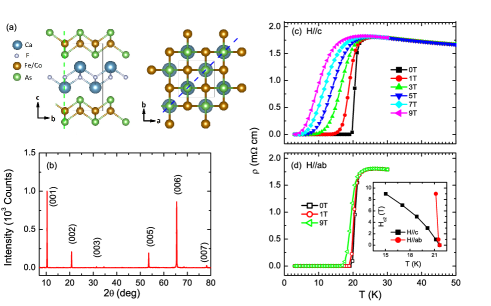
The first-principles calculations presented in this work were performed using the all-electron full potential linear augmented plane wave plus local orbitals (FP-LAPW + lo) method LAPW as implemented in the WIEN2K code. wien2k The exchange-correlation potential was calculated using the generalized gradient approximation (GGA) as proposed by Pedrew, Burke, and Ernzerhof. PBE These calculations were performed using the experimental crystal structure 20 , as shown in Fig. 1(a).
III Results
The x-ray was incident on the -plane of the sample when carrying out the x-ray diffraction measurements. The diffraction pattern is shown in Fig. 1(b), which follows the tetragonal ZrCuSiAs-type structure. It is important to point out that only the sharp peaks along the (00) orientation are observed, suggesting a high -axis orientation. The actual doping level of cobalt was determined to be 0.118 by the energy dispersive x-ray spectroscopy. Detailed analysis and discussions about the crystal structure and the chemical composition have been reported in our previous paper. CaFeAsF-Co Temperature dependence of electronic resistivity is shown in Fig. 1(c) and (d). Under zero field, the sample exhibits a sharp SC transition at (onset) = 21.6 K (90) with a transition width = 1.7 K (10%-90 ), where is the resistivity of the normal state before the SC transition, demonstrating the high quality of our single crystal samples. The slightly semiconducting behavior just above along with the value indicates that the present sample locates on the slightly underdoped region near the optimal doped point of the phase diagram.
We perform the measurements of temperature dependent electronic resistivity with the magnetic field along various orientations to study the anisotropy effect of of superconductor CaFe1-xCoxAsF. As shown in Fig. 1(c) and (d), the SC transition point shifts to lower temperature with the increase of the magnetic field for both the orientations of parallel and perpendicular to -axis of the crystal structure. It is worthy to note that the SC transition for the orientation of shifts much quicker than that of by comparing the data from Fig. 1(c) and (d). Quantitatively, we use to determine the upper critical field . The temperature dependence of is shown in the inset of Fig. 1(d) for both the two orientations, and the value of anisotropy parameter is estimated to be at temperature of 21.2 K.
To gain more information about the anisotropy effect of , we further measure the magnetic-field-angle dependence of electronic resistivity under various magnetic fields at the temperature region near the SC transition point. Here we take the data at the temperature of 19 K as an example and plot it in Fig. 2(a). In addition, the schematic illustration of applied magnetic field and the dc current is also shown in the inset of Fig. 2(a). The positive magnetoresistivity displays a V-shaped structure with occurring the minimum at = 90∘ and maximum at = 0∘ and = 180∘. Similar results are also obtained for other temperatures indicating the universal behaviours of magnetic-field-angle dependent magnetoresistivity. Based on the anisotropic GL theory, the effective upper critical field as a function of the orientation of azimuth angle is expressed as Blatter1 :
| (1) |
Here, it should be noted that the resistivity in the superconducting state merely depends on the effective magnetic field , i.e., , at a given temperature. Blatter2 According to the Eq. (1), we rewrite the resistivity as a function of , and show it in Fig. 2(b). It clearly demonstrates the universal behaviors that all magnetic field dependent electronic resistivity falls into one curve at a fixed temperature. In addition, temperature dependence of the fitted anisotropic parameter is also shown in Fig. 1(c). For a comparison, we also show a consistent value of anisotropic parameter estimated from . Importantly, these anisotropic values are much larger than that reported on other FeSCs.
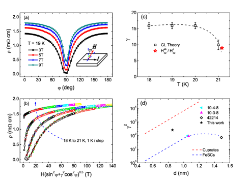
In Fig. 2(d), we also show the values at 0.85 as a function of the distance between the neighboring conducting layers (FeAs layers or CuO2 layers). The two dashed lines, respectively, represent the tendency of the previously reported FeSCs and cuprates superconductors. 10-4-8 Generally speaking, the value of for FeSCs is two orders of magnitude lower than that of cuprates superconductors with the same value of . Exceptionally, the value of CaFe0.882Co0.118AsF locates above the blue dashed line which indicates a common tendency of FeSCs, and even higher than the 10-3-8, 10-4-8 and 42214 systems [Ca10(PtnAs8)(Fe2-xPtxAs2)5 (n = 3, 4), Pr4Fe2As2Te1-xO4] with a much larger space between the FeAs layers. 10-4-8 ; 42214
IV Discussion
Although we have found the largest anisotropy parameter of CaFe0.882Co0.118AsF in iron-based superconductors, the experimental observation is consistent with the theoretical prediction by the first-principal calculations. Previously, D. J. Singh et al Singh1 predicted the anisotropy to be about 15 for the parent phase of the 1111 system after the discovery of the high- FeSCs. Since the anisotropy is tightly related to the electronic structure, and as we known that the Fermi surface of FeSCs consists of five sheets, where two electron-like cylinders centered around the M-A line and two hole-like cylinders around the -Z line, as well as an additional small 3D hole-like pocket centered at Z point, individual characters in details of the electronic structure may have remarkable influences on the anisotropic effect of the materials, such as the strong warping of the electron pockets in the 122, 111, and 11 systems, compared with the 1111 system, Singh1 ; Singh2 ; FeSeTe can be expected to increase the tendency of 3D characterizations, which may explain the fact that the anisotropy parameter of these three systems is smaller than of the 1111 system.
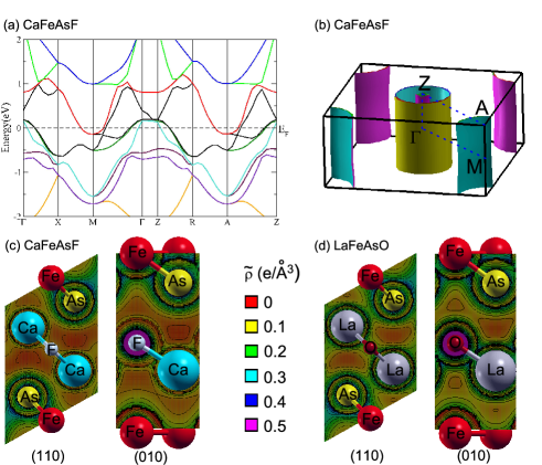
In order to examine the detailed electronic structure of CaFe0.882Co0.118AsF and clarify the nature of the emergence of strongest electronic anisotropy among the FeSCs, we carried out the first-principles calculations. The electronic band structure should be changed slightly by the cobalt doping of 11.8% based on the rigid-band approximation. For simplicity, we just only show the energy band and its Fermi surface topology of CaFeAsF in Fig. 3(a) and (b), respectively, which are in good agreement with previous report. Shein Firstly we examine the energy dispersions between high symmetric -points of and , there is no band intersects across the Fermi level. This result indicates the absence of the 3D Fermi pocket around the point. In addition, it is found that all of the Fermi surface sheets are almost ideal cylinders [see Fig. 3(b)]. Previously, I. A. Nekrasov et al have pointed out that the fluorine-based 1111 system displays a much more perfect 2D character of the Fermi surfaces than the oxygen-based 1111 system LaFeAsO Nekrasov . As for the compounds with an even larger interlayer distance like the 10-3-8 system, both the ARPES measurements and first-principles calculations have demonstrated a strong 3D character in the topology of the Fermi surface stemming from the strong hybridization with the Pt orbitals. 10-3-8 This should definitely suppress the bidimensionality of the Fermi surface. The perfect bidimensionality of CaFeAsF may explain the experimental fact of the strong anisotropy of CaFe0.882Co0.118AsF qualitatively.
Quantatively, we calculated the charge density distribution, , as shown in Fig. 3(c). For comparison, we also performed the charge density distribution calculation for the system of LaFeAsO with the same crystal structure of CaFeAsF and shown in Fig. 3(d). From the distribution of in the (110) plane, it displays no difference of the around Fe-As bond between LaFeAsO and CaFeAsF, but the in the area of La-As has clearly much higher value than that in the area of Ca-As, suggesting the weakness of the interlayer coupling between the layers of FeAs and CaF. This result is also understandable because the strong electronegativity of F favors to form the much stronger ionic binding with Ca, as revealed by the lower values of in between Ca2+ and F- ions in the (010) plane, and weakens the interlayer coupling. This mechanism well explains the nature of such a strong electronic anisotropy observed in experiments in the system of CaFeAsF.
V Conclusions
In summary, magnetic field angular dependence of resistivity in the superconducting state was measured on the single crystals of CaFe0.882Co0.118AsF. The obtained anisotropy parameter based on the anisotropic Ginzburg-Landau theory is much larger than that of other FeSCs. By the charge density distribution calculations, we found that the strong electronic anisotropy mainly comes from the strong intra-layer ionic bonding in CaF layer, which weakens the interlayer coupling between the layers of FeAs and CaF. Our results demonstrate that the fluorine-base 1111 system may be the most 2D superconducting material in FeSCs, from the viewpoint of electronic structure. The interplay between strong electronic anisotropy and unconventional superconductivity is an important issue for the understanding the mechanism of unconventional superconductor, which deserves our attentions in the future.
Acknowledgements.
This work is supported by the National Natural Science Foundation of China (Nos. 11204338 and 11404359), the “Strategic Priority Research Program (B)” of the Chinese Academy of Sciences (Nos. XDB04040300, and XDB04030000) and Youth Innovation Promotion Association of the Chinese Academy of Sciences (Nos. 2015187 and 2016215).References
- (1) Y. Kamihara, T. Watanabe, M. Hirano and H. Hosono, J. Am.Chem. Soc. 130, 3296 (2008).
- (2) M. Putti, I. Pallecchi, E. Bellingeri, M. R. Cimberle, M. Tropeano, C. Ferdeghini, A. Palenzona, C. Tarantini, A. Yamamoto, J. Jiang, J. Jaroszynski, F. Kametani, D. Abraimov, A. Polyanskii, J. D. Weiss, E. E. Hellstrom, A. Gurevich, D. C. Larbalestier, R. Jin, B. C. Sales, A. S. Sefat, M. A. McGuire, D. Mandrus, P. Cheng, Y. Jia, H. H. Wen, S. Lee and C. B. Eom, Supercond. Sci. Technol. 23, 034003 (2010).
- (3) H. Hosono, K. Tanabe, E. T. Muromachi, H. Kageyama, S. Yamanaka, H. Kumakura, M. Nohara, H. Hiramatsu and S. Fujitsu, Sci. Technol. Adv. Mater. 16, 033503 (2015).
- (4) V. G. Kogan and R. Prozorov, Rep. Prog. Phys. 75, 114502 (2012).
- (5) J. A. Wilson, F. J. Di Salvo, and S. Mahajan, Adv. Phys. 24, 117 (1975).
- (6) G. Grüner, Rev. Mod. Phys. 60, 1129 (1988).
- (7) C. Cruz, Q. Huang, J. W. Lynn, J. Li, W. Ratcliff, J. L. Zarestky, A. H. Mook, G. F. Chen, J. L. Luo, N. l. Wang, P. C. Dai, Nature 453, 899 (2008).
- (8) J. Shimoyama, K. Kitazawa, K. Shimizu, S. Ueda, S. Horii, N. Chikumoto and K. Kishio, Low Temp. Phys. 131, 1043 (2003).
- (9) K. Zhao, B. Lv, Y. Xue, X. Zhu, L. Deng, Z. Wu, and C. W. Chu, Phys. Rev. B 92, 174404 (2015).
- (10) Y. Jia, P. Cheng, L. Fang, H. Yang, C. Ren, L. Shan, C. Z. Gu and H. H. Wen, Supercond. Sci. Technol. 21, 105018 (2008).
- (11) F. F. Yuan, Y. Sun, W. Zhou, X. Zhou, Q. P. Ding, K. Iida, R. Hühne, L. Schultz, T. Tamegai and Z. X. Shi, Appl. Phys. Lett. 107, 012602 (2015).
- (12) S. Khim, B. Lee, J. W. Kim, E. S. Choi, G. R. Stewart and K. H. Kim, Phys. Rev. B 84, 104502 (2011).
- (13) M. H. Fang, J. H. Yang, F. F. Balakirev, Y. Kohama, J. Singleton, B. Qian, Z. Q. Mao, H. D. Wang and H. Q. Yuan, Phys. Rev. B 81, 020509 (2010).
- (14) F. F. Yuan, K. Iida, M. Langer, J. Hänisch, A. Ichinose, I. Tsukada, A. Sala, M. Putti, R. Hühne, L. Schultz and Z. X. Shi, Supercond. Sci. Technol. 28, 065005 (2015).
- (15) Y. Sun, T. Taen, Y. Tsuchiya, Q. P. Ding, S. Pyon, Z. X. Shi and T. Tamegai, Appl. Phys. Express 6, 043101 (2013).
- (16) D. J. Singh and M. H. Du, Phys. Rev. Lett. 100, 237003 (2008).
- (17) S. Khim, B. Lee, J. W. Kim, E. S. Choi, G. R. Stewart and K. H. Kim, Phys. Rev. B 84, 104502 (2011).
- (18) G. Fuchs, S. L. Drechsler, N. Kozlova, M. Bartkowiak, G. Behr, K. Nenkov, H. H. Klauss, J. Freudenberger, M. Knupfer, F. Hammerath, G. Lang, H. J. Grafe, B. Buechner and L. Schultz, Physica C 470, S288 (2010).
- (19) S. Zhang, Y. P. Singh, X. Y. Huang, X. J. Chen, M. Dzero and C. C. Almasan, Phys. Rev. B 92, 174524 (2015).
- (20) Y. H. Ma, H. Zhang, B. Gao, K. K. Hu, Q. C. Ji, G. Mu, F. Q. Huang and X. M. Xie, Supercond. Sci. Technol. 28, 085008 (2015).
- (21) Y. H. Ma, K. K. Hu, Q. C. Ji, B. Gao, H. Zhang, G. Mu, F. Q. Huang and X. M. Xie, Journal of Crystal Growth 451, 161 (2016).
- (22) H. Xiao, B. Gao, Y. H. Ma, X. J. Li, G. Mu and T. Hu, J. Phys.: Condens. Matter 28, 455701 (2016).
- (23) H. Xiao, B. Gao, Y. H. Ma, X. J. Li, G. Mu and T. Hu, J. Phys.: Condens. Matter 28, 325701 (2016).
- (24) S. Weyeneth, R. Puzniak, N. D. Zhigadlo, S. Katrych, Z. Bukowski, J. Karpinski and H. Keller, J Supercond Nov Magn 22, 347-351 (2009).
- (25) M. Bendele, S. Weyeneth, R. Puzniak, A. Maisuradze, E. Pomjakushina, K. Conder, V. Pomjakushin, H. Luetkens, S. Katrych, A. Wisniewski, R. Khasanov, and H. Keller, Phys. Rev. B 81, 224520 (2010).
- (26) D. J. Singh and L. Nordstrom, Planewaves, Pseudopotentials, and the LAPW Method, 2nd ed. (Springer-Verlag, Berlin, 2006).
- (27) P. Blaha, K. Schwarz, G. Madsen, D. Kvasnicka, and J. Luitz, in WIEN2K, An Augmented PlaneWave + Local Orbitals Program for Calculating Crystal Properties, edited by K. Schwarz (Technical Univievsity Wien, Austria, 2001).
- (28) J. P. Perdew, K. Burke and M. Ernzerhof, Phys. Rev. Lett. 77, 3865 (1996).
- (29) G. Blatter, M. V. Feigel’man, V. B. Geshkenbein, A. I. Larkin and V. M. Vinokur, Rev. Mod. Phys. 66, 1125 (1994).
- (30) G. Blatter, V. B. Geshkenbein and A. I. Larkin, Phys. Rev. Lett. 68, 875 (1992).
- (31) A. Pisoni, P. Szirmai, S. Katrych, B. Náfrádi, R. Gaál, J. Karpinski, and L. Forró, Phys. Rev. B 93, 094519 (2016).
- (32) D. J. Singh, Phys. Rev. B 78, 094511 (2008).
- (33) B. Zeng, G. Mu, H. Luo, T. Xiang, I. I. Mazin, H. Yang, L. Shan, C. Ren, P C. Dai and H. H. Wen, Nat. Commun. 1, 112 (2010).
- (34) I. R. Shein and A. L. Ivanovskii, JETP Letters 88, 683 (2008).
- (35) I. A. Nekrasov, Z. V. Pchelkina and M. V. Sadovskii, JETP Letters 88, 679 (2008).
- (36) M. Neupane, C. Liu, S. Y. Xu, Y. J. Wang, N. Ni, J. M. Allred, L. A. Wray, N. Alidoust, H. Lin, R. S. Markiewicz, A. Bansil, R J. Cava, and M. Z. Hasan, Phys. Rev. B 85, 094510 (2012).