Crystal and Magnetic Structures in Layered, Transition Metal Dihalides and Trihalides
Abstract
Materials composed of two dimensional layers bonded to one another through weak van der Waals interactions often exhibit strongly anisotropic behaviors and can be cleaved into very thin specimens and sometimes into monolayer crystals. Interest in such materials is driven by the study of low dimensional physics and the design of functional heterostructures. Binary compounds with the compositions and where is a metal cation and is a halogen anion often form such structures. Magnetism can be incorporated by choosing a transition metal with a partially filled -shell for , enabling ferroic responses for enhanced functionality. Here a brief overview of binary transition metal dihalides and trihalides is given, summarizing their crystallographic properties and long-range-ordered magnetic structures, focusing on those materials with layered crystal structures and partially filled d-shells required for combining low dimensionality and cleavability with magnetism.
I Introduction
Binary transition metal halides ( metal cation, halogen anion) provide a rich family of materials in which low dimensional magnetism can be examined, and such studies were carried out through much of the last century de Jongh (1990). The dihalides contain triangular nets of transition metal cations, and geometrical frustration is expected when the magnetic interactions are antiferromagnetic (AFM) Kadowaki et al. (1987); Ramirez (1994); Collins and Petrenko (1997). Several of the compounds form helimagnetic structures and display multiferroic behavior Tokunaga et al. (2011); Kurumaji et al. (2011); Wu et al. (2012); Kurumaji et al. (2013). In the trihalides, on the other hand, the transition metal cations form honeycomb nets. This lattice is not frustrated for simple AFM nearest neighbor interactions, but in the case of RuCl3 more complex magnetic interactions and spin-orbit coupling are expected to result in a spin-liquid ground state that is currently of much interest Plumb et al. (2014); Kim et al. (2015); Sears et al. (2015); Johnson et al. (2015); Banerjee et al. (2016). For many of the materials considered here, the in plane interactions are ferromagnetic (FM). Chromium trihalides were identified as some of the earliest ferromagnetic semiconductors, and Cr compounds in general have received recent attention as candidate materials for the study of magnetic monolayers and for use in van der Waals heterostructures, in which their magnetism can be coupled to electronic and optical materials via proximity effects Geim and Geigorieva (2013); Wang et al. (2011); McGuire et al. (2015); Zhang et al. (2015); Liu et al. (2016); Wang et al. (2016); Zhong et al. (2017); Huang et al. (2017). Developing cleavable ferroic materials, both magnetic and electric, is key to expanding the toolbox available for designing and creating custom, functional heterostructures and devices Lebègue et al. (2013); Ajayan et al. (2016); Park (2016). Although FM and ferroelectric materials play the most clear role in such applications, the development of spintronics employing antiferromagnetic materials may open the door to a much larger set of layered transition metal halides MacDonald and Tsoi (2011); Gomonay and Loktev (2014); Jungwirth et al. (2016).
It is generally observed that binary halides often form low dimensional crystal structures, comprising either molecular units, one dimensional chains, or two dimensional layers. This holds true especially for the chlorides, bromides, and iodides, and can be attributed to the low ionic charge and relatively large ionic radii (1.8–2.2 Å) of these anions. This results in multiple large anions for each metal cation assuming oxidation states typical for transition metals. Thus the cations are usually found in six-fold coordination and are well separated into structural units that are joined to one another in the crystal by van der Waals bonding between halogen anions. Fluoride has a much smaller ionic radius (1.3 Å) and forms three dimensional crystal structures with the divalent and trivalent cations that are the focus of most of this work. Note that this simple ionic picture is not appropriate when metal-metal bonding is present, which is often the case in the early, heavy transition metals. Typically larger anion to cation ratios result in lower dimensional structures, but often polymorphs of different dimensionality occur for a single composition. For example, TiCl3 forms with 1D chains of face sharing octahedra or 2D layers of edge sharing octahedra Klemm and Krose (1947); Natta et al. (1961). Dihalides () and trihalides () represent the majority of layered binary transition metal halides. There are, however, other examples, including Nb3Cl8 von Schnering et al. (1961), in which interesting magnetic behavior has been noted recently Sheckelton et al. (2017); Jiang et al. (2017).
Here, a brief review of and compounds with partially filled -shells is presented, with a focus on crystal and magnetic structures. A general overview of the crystallographic properties and magnetic behavior including static magnetic order in these two families is given. This short survey is not meant to be exhaustive, but rather to give a general introduction to these materials and a broad overview of the trends observed in their crystallographic and magnetic properties, with references to the literature where more detailed discussion can be found.
| Compound | Structure Type | Ref. | in Plane | Layer | Magnetic Order | Moments | ||
|---|---|---|---|---|---|---|---|---|
| Distance (Å) | Spacing (Å) | in Layer | (K) | (K) | ||||
| TiCl2 | CdI2 () | Baenziger and Rundle (1948) | 3.56 | 5.88 | AFM | – | 85 | 702 |
| TiBr2 | CdI2 () | Ehrlich et al. (1961) | 3.63 | 6.49 | – | – | – | – |
| TiI2 | CdI2 () | Klemm and Grimm (1942) | 4.11 | 6.82 | – | – | – | – |
| VCl2 | CdI2 () | Villadsen (1959) | 3.6 | 5.83 | AFM | 120∘ | 36 | 565, 437 |
| VBr2 | CdI2 () | Klemm and Grimm (1942) | 3.77 | 6.18 | AFM | 120∘ | 30 | 335 |
| VI2 | CdI2 () | Kuindersma et al. (1979) | 4.06 | 6.76 | AFM | – | 16.3, 15 | 143 |
| MnCl2 | CdCl2 () | Tornero and Fayos (1990) | 3.71 | 5.86 | AFM or HM | stripe or HM | 2.0, 1.8 | 3.3 |
| MnBr2 * | CdI2 () | Wollan et al. (1958) | 3.89 | 6.27 | AFM | stripe | 2.3, 2.16 | – |
| MnI2 | CdI2 () | Ferrari and Giorgi (1929a) | 4.16 | 6.82 | HM | HM | 3.95, 3.8, 3.45 | – |
| FeCl2 | CdCl2 () | Vettier and Yellon (1975) | 3.6 | 5.83 | AFM | FM | 24 | 9 (), 21 () |
| FeBr2 | CdI2 () | Haberecht et al. (2001) | 3.78 | 6.23 | AFM | FM | 14 | 3.0 (), 3.5 () |
| FeI2 | CdI2 () | Gelard et al. (1974) | 4.03 | 6.75 | AFM | stripe | 9 | 24 (), 21.5 () |
| CoCl2 | CdCl2 () | Grimme and Santos (1934) | 3.54 | 5.81 | AFM | FM | 25 | 38 |
| CoBr2 | CdI2 () | Ferrari and Giorgi (1929b) | 3.69 | 6.12 | AFM | FM | 19 | – |
| CoI2 | CdI2 () | Ferrari and Giorgi (1929a) | 3.96 | 6.65 | HM | HM | 11 | – |
| NiCl2 | CdCl2 () | Ferrari et al. (1963) | 3.48 | 5.8 | AFM | FM | 52 | 68 |
| NiBr2 | CdCl2 () | Nasser et al. (1992) | 3.7 | 6.09 | AFM, HM | FM , HM | 52, 23 | – |
| NiI2* | CdCl2 () | Ketalaar (1934) | 3.9 | 6.54 | HM | HM | 75 | – |
| ZrCl2 | MoS2 () | Cisar et al. (1979) | 3.38 | 6.45 | – | – | – | – |
| ZrI2 | MoTe2 () | Guthrie and Corbett (1981) | 3.18, 3.74, 4.65 | 7.43 | – | – | – | – |
| ZrI2 | WTe2 () | Corbett and Guthrie (1982) | 3.19, 3.74, 4.65 | 7.44 |
II Crystal Structures of Layered, Binary, Transition Metal Halides
II.1 MX2 Compounds
| Compound | Structure Type | Ref. | in Plane | Layer | Magnetic Order | Moments | or | |
|---|---|---|---|---|---|---|---|---|
| Distance (Å) | Spacing (Å) | in Layer | (K) | (K) | ||||
| TiCl3 * | BiI3 () | Klemm and Krose (1947) | 3.53 | 5.83 | – | – | – | – |
| TiCl3 * | Ti3O () | Troyanov et al. (1991) | 3.55 | 5.86 | ||||
| TiBr3 * | BiI3 () | Troyanov et al. (1990) | 3.74 | 6.21 | – | – | – | – |
| VCl3 | BiI3 () | Klemm and Krose (1947) | 3.47 | 5.78 | AFM | – | 20 | 30 |
| VBr3 | BiI3 () | McCarley et al. (1964) | 3.7 | 6.21 | – | – | – | – |
| CrCl3 * | AlCl3 () | Morosin and Narath (1964) | 3.44, 3.44 | 5.80 | AFM | FM | 15.5, 16.8 | 27 |
| CrBr3 * | BiI3 () | Handy and Gregory (1952) | 3.64 | 6.11 | FM | FM | 37 | 47 |
| CrI3 * | AlCl3 () | McGuire et al. (2015) | 3.96, 3.97 | 6.62 | FM | FM | 61 | 70 |
| FeCl3 | BiI3 () | Hashimoto et al. (1989) | 3.50 | 5.80 | HM | HM | 9–10 | 11.5 |
| FeCl3 | Ti3O () | Troyanov (1993) | 3.50 | 5.80 | ||||
| FeCl3 | FeCl3 () | Troyanov (1993) | 3.50 | 5.81 | ||||
| FeBr3 | BiI3 () | Armbrüster et al. (2000) | 3.69 | 6.13 | AFM | – | 15.7 | – |
| MoCl3 | AlCl3 () | Schäfer et al. (1967) | 2.76, 3.71 | 5.99 | – | – | – | – |
| TcCl3 | AlCl3 () | Poineau et al. (2012) | 2.86, 3.60 | 5.86 | – | – | – | – |
| RuCl3 * | AlCl3 () | Cao et al. (2016) | 3.45, 3.45 | 5.69 | AFM | zig-zag canted | 7–8, 13–14 | 37 (), 150() |
| RuCl3 * | Ti3O () | Fletcher et al. (1967) | 3.45 | 5.72 | ||||
| RuCl3 * | CrCl3 () | Stroganov and Ovchinnikov (1957) | 3.44, 3.45 | 5.73 | ||||
| RhCl3 | AlCl3 () | Bärnighausen and Handa (1964) | 3.44, 3.43 | 5.70 | – | – | – | – |
| RhBr3 | AlCl3 () | Brodersen et al. (1968a) | 3.62, 3.62 | 6.00 | – | – | – | – |
| RhI3 | AlCl3 () | Brodersen et al. (1968a) | 3.91, 3.90 | 6.45 | – | – | – | – |
| IrCl3 | AlCl3 () | Brodersen et al. (1965) | 3.46, 3.45 | 5.64 | – | – | – | – |
| IrBr3 | AlCl3 () | Brodersen et al. (1968b) | 3.67, 3.64 | 6.01 | – | – | – | – |
| IrI3 | AlCl3 () | Brodersen et al. (1968b) | – | 6.54 | – | – | – | – |
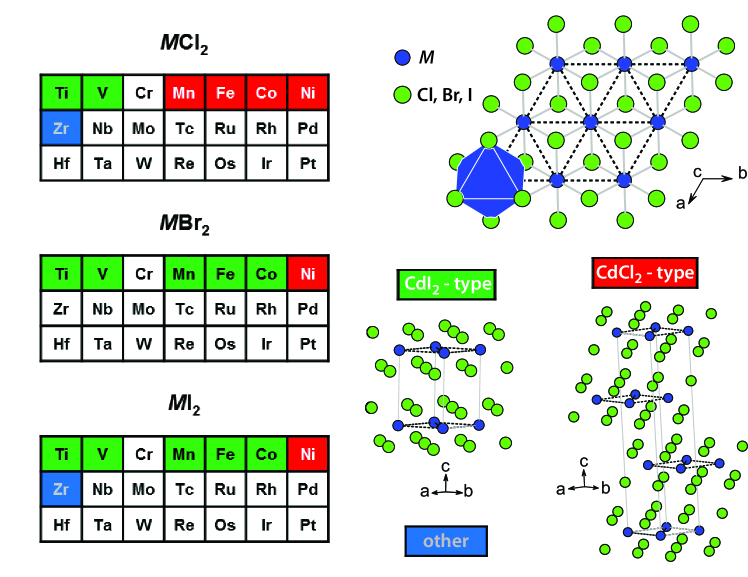
Crystal structure information for compounds with partially filled -shells is collected in Table 1. Non-magnetic, layered dihalides of Zn, Cd, and Hg, with valence electronic configurations 3, 4, and 5, respectively, are also known Brehzer (1959); Yamaguchi (1942a, b); Pauling (1929); Mitchell (1962); Bozorth (1922); Bijvoet et al. (1926), but these are not considered here. It can be seen that most of the compounds in Table 1 adopt either the trigonal CdI2 structure type or the rhombohedral CdCl2 structure type. These structures are shown in Figure 1. Both contain triangular nets of cations in edge sharing octahedral coordination forming layers of composition separated by van der Waals gaps between the anions. The structures differ in how the layers are stacked. The CdI2 structure type has AA stacking with one layer per unit cell, and the anions adopt a hexagonal close packed arrangement. The CdCl2 structure has ABC stacking with three layers per unit cell, and the anions adopt a cubic close packed arrangement.
Figure 1 also shows sections of the periodic table highlighting the transition metals for which the compounds listed in Table 1 form. Note that compounds with stoichiometry are known for other , for example Cr, Mo, and Pd, but they form molecular (cluster) compounds or 1D chain structures. Among the dichlorides, the CdCl2 structure is found only for the later transition metals, and only for Ni in the dibromides and diiodides. However, Schneider et al. have shown that MnBr2 may undergo a crystallographic phase transition from the CdI2 structure type to the CdCl2 structure type at high temperature Schneider et al. (1992). NiI2 undergoes a crystallographic phase transition at 60 K Kuindersma et al. (1981). It is monoclinic below this temperature, resulting from a slight distortion () from the C-centered orthorhombic description of the hexagonal lattice. In addition, diffraction measurements on FeCl2 under pressure have shown a transition from the CdCl2 structure to the the CdI2 structure near 0.6 GPa Narath and Schirber (1966); Rozenberg et al. (2009).
Interatomic distances between cations within the layers and the spacing of the layers are shown in Table 1. For the CdCl2 and CdI2 structure types the in-plane distance is equal to the length of the crystallographic axis (hexagonal settings). The layer spacing, defined as the distance between the midpoints of neighboring layers measured along the stacking direction, is equal to the length of the axis in the CdI2 structure and /3 in the CdCl2 structure. Moving across the series from Mn to Ni, both of these distances generally decrease, while less systematic behavior is seen for Ti and V.
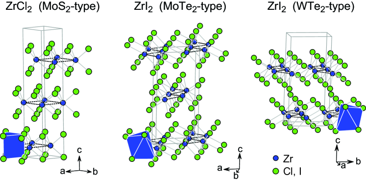
The layered phases are restricted to the first row of the transition metals, with the exception of the 4 element Zr. Both ZrCl2 and ZrI2 are reported, but not the dibromide. The zirconium compounds are found to have different structures than the layered 3 transition metal dihalides. As shown in Figure 2, ZrCl2 adopts the MoS2 structure type Cisar et al. (1979), which has the same triangular nets of metal cations and ABC stacking found in CdCl2. However, in ZrCl2 the Zr atoms are in trigonal prismatic coordination rather than octahedral coordination. As a result the Cl anions do not form a cubic close packed arrangement in ZrCl2 but instead an AABBCC stacking sequence. ZrI2 is reported to adopt both the MoTe2 and WTe2 structure types Guthrie and Corbett (1981); Corbett and Guthrie (1982). The closely related structures are shown in Figure 2. The regular triangular net of cations found in the compounds described previously is disrupted in ZrI2, which has zigzag chains of Zr atoms (see in-plane distances in Table 1). This points to the tendency of heavier (4 and 5) transition metals to form metal-metal bonds. Indeed, in addition to the layered MoS2 structure described above for ZrCl2, a molecular crystal structure with Zr6 clusters is also known Imoto et al. (1981). Further examples of this tendency will be noted later in discussion of compounds.
II.2 MX3 Compounds
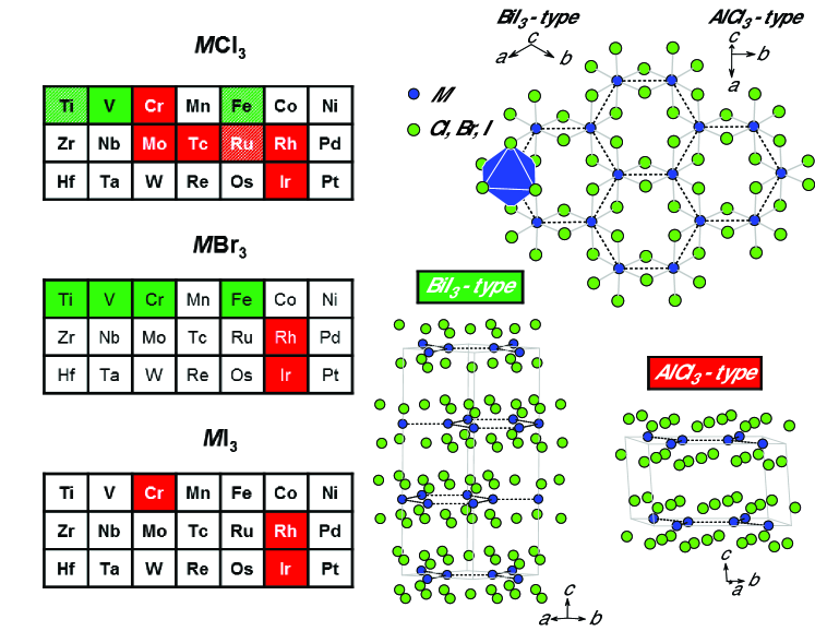
Crystal structure information for layered compounds is collected in Table 2. Only compounds with transition metals containing partially filled d-shells are included, since those are the materials in which magnetism may be expected. Non-magnetic, layered trihalides of Sc and Y, with valence electronic configurations 3 and 4, respectively, are also known Klemm and Krose (1947); Men’kov and Komissarova (1964a, b); Templeton and Darter (1954); Brown et al. (1968); Jongen and Meyer (2005). Note that several of these materials also form in 1D chain structures, but those polymorphs are outside of the scope of the present work. All of the layered compounds have been reported to adopt either the monoclinic AlCl3 structure type or the rhombohedral BiI3 structure type, and this is indicated for each element on the periodic table sections shown in Figure 3. In these materials the common structural motif is a honeycomb net of cations that are in edge sharing octahedral coordination, as shown in Figure 3. In the BiI3 structure the layer stacking sequence is strictly ABC, and the stacking in AlCl3 is approximately ABC. In the former case subsequent layers are shifted along one of the “bonds” (to the right in the BiI3 structure shown in Figure 3), while in the latter case the layers are shifted perpendicular to this direction (into the page in the AlCl3 structure shown in Figure 3).
In the BiI3 structure the honeycomb net is regular due to the three-fold symmetry. In the AlCl3 structure the honeycomb net can be distorted, and the y-coordinate of the site determines the degree of distortion. This results in two unique in-plane distances (Table 2). In most of the compounds these two distances are seen to be quite similar, that is the honeycomb nets are nearly undistorted. The two exceptions are the heavier transition metal compounds MoCl3 and TcCl3, in which the net is broken into dimers that are separated from one another by a distance about one Angstrom longer than their intradimer distance. Metal-metal bonding in Tc halides including layered () TcCl3 is discussed in [86].
Three elements, Ti, Fe, and Ru, are reported to form multiple layered crystal structures with stoichiometry Cl3 (Table 2). This is indicated by the crosshatching on the table in Figure 3. As noted in Table 2, TiCl3 is also reported to form in the trigonal Ti3O structure type. This is similar to the BiI3 structure shown in Figure 3, but with an ABB stacking sequence. This same structure type is also found for one of the FeCl3 polymorphs, which also forms in a third structure type (trigonal, ) with twelve honeycomb layers per unit cell and a axis length of 70 Å.
TiCl3 undergoes a structural phase transition at low temperature Ogawa (1960). Troyanov et al. demonstrated that the distortion upon cooling corresponds to a dimerization similar to that noted above in MoCl3 and TcCl3 Troyanov et al. (1991). Below 220 K a monoclinic structure was reported. The space group, is the same as the AlCl3 structure type, but the structure is different, with three layers per unit cell. The dimerization is not as extreme in TiCl3 as it is in MoCl3 and TcCl3. At 160 K the Ti-Ti distances within the distorted honeycomb net are 3.36 and 3.59 Å Troyanov et al. (1991), so the dimerization is not as strong at this temperature, 60 K below the transition, as it is in MoCl3 and TcCl3 (Table 2) at room temperature. A structural phase transition is also reported for TiBr3, with a triclinic low temperature structure () Troyanov et al. (1994), and this same triclinic structure was also later reported for TiCl3 Troyanov and Snigireva (2000).
All three of the layered chromium trihalides are known to undergo temperature induced crystallographic phase transitions between the AlCl3 and BiI3 structure types Morosin and Narath (1964); McGuire et al. (2015). At high temperatures all three adopt the AlCl3 structure and transition to the BiI3 structure upon cooling. This happens near 240, 420, and 210 K in the chloride, bromide, and iodide, respectively. The phase transition is first order, displaying thermal hysteresis and a temperature range over which both phases coexist. Interestingly, it is the lower symmetry monoclinic phase that is preferred at higher temperatures. The transition must be driven by interlayer interactions, since the layers themselves are changed little between the two phases. As expected, twinning and stacking faults develops during the transition upon cooling as the layers rearrange themselves into the BiI3 stacking, which can complicate interpretation of diffraction data McGuire et al. (2015).
Multiple structure types have been assigned to the layered form of RuCl3, known as -RuCl3. Early reports assigned the trigonal space group Stroganov and Ovchinnikov (1957) (known as the CrCl3 structure type, although it has been shown that CrCl3 does not actually adopt it) and the AlCl3 type Brodersen et al. (1965), and a tendency to form stacking defects has been noted Brodersen et al. (1968b). The Ti3O type was also reported Fletcher et al. (1967). More recently an X-ray and neutron diffraction study reported the monoclinic AlCl3 structure for small single crystals at and below room temperature, and a phase transition in large single crystals from a trigonal structure at room temperature to the monoclinic AlCl3 structure type below about 155 K Cao et al. (2016). A recent report finds high quality crystals undergo a crystallographic phase transition upon cooling from the AlCl3-type at room temperature to the BiI3-type below about 60 K Park et al. (2016), the same transition described above for Cr. Note that even in the monoclinic form the honeycomb net of Ru has little or no distortion (Table 2).
Finally, layered IrCl3 has the AlCl3 structure with a nearly regular honeycomb net (Table 2), but it is also known to adopt a less stable orthorhombic polymorph (). The orthorhombic structure is made up of edge sharing octahedra like the layered structure, but the connectivity extends the structure in three dimensions Babel and Deigner (1965). It is interesting to note that the structure of orthorhombic IrCl3 is made up of fragments of honeycomb nets like those found in the layered structures shown in Figure 3.
Clearly there are many variants on the stacking sequence in these layered materials due to the weak van der Waals interactions between layers that results in small energy differences between arrangements with different stacking sequences. This is apparent from the crystallographic results from the Ti, Cr, Fe, and Ru trichlorides discussed above. This has been demonstrated using first principles calculations for RuCl3 where multiple structures are found to be very close in energy, and the ground state can depend on the fine details of spin-orbit coupling and electron correlations Kim and Kee (2016). The possibility of mechanically separating these materials into thin specimens or even monolayers is of great interest from the point of view of low dimensional magnetism and potential applications and is greatly facilitated by the weakness of the interlayer interactions. The cleavability of several of these compounds has been studied with first principles calculations, using density functionals that incorporate the weak interlayer dispersion forces that are missing from many conventional functionals. For the Ti, V, and Cr trihalides, cleavage energies are reported to be near 0.3 J/m2, which is smaller than that of graphite McGuire et al. (2015); Zhang et al. (2015); Zhou et al. (2016). Stable monolayer crystals of CrI3 have recently been demonstrated experimentally Huang et al. (2017).
III Magnetic Structures of Layered, Binary, Transition Metal Halides
The magnetic order in layered and compounds is described below, and some description of the high temperature paramagnetic behavior is given as well. Magnetic excitations and magnetic correlations that develop above the long range ordering temperature are not considered here. Magnetism in these insulating transition metal halide compounds arises from the angular momentum associated with partially filled d orbitals. In octahedral coordination, interaction with the coordinating anions split the five d orbitals into a set of three levels at lower energy, the levels (), and two levels at higher energy, the levels (). According to Hund’s rules, the electrons first fill these states singly with their spins parallel, unless the energy cost of putting electrons in the higher energy states overcomes the cost of doubly occupying a single state. In addition to their spin, the electrons in these levels also have orbital angular momentum. In ideal octahedral coordination, the total orbital angular momentum can be shown to be zero for certain electronic configurations. This arises due to rotational symmetry of the system, and when this occurs the orbital angular momentum is said to be “quenched”. For octahedral coordination the orbital angular momentum is quenched when there is exactly one electron in each of the orbitals, and when there are two electrons in each of the orbitals. Otherwise there is an orbital moment that must be considered. There is no orbital angular momentum associated with the orbitals. Of course, distortions of the octahedral environments can affect the details of the magnetism that are based on symmetry and degeneracy of electronic states. Despite the partially filled -orbitals, the materials considered here are electrically insulating under ambient conditions. This can be attributed to a Mott-Hubbard type mechanism by which electron-electron interactions produce a band gap related to the Coulomb repulsion among the well-localized electrons (see for example Khomskii (2014)).
Magnetism in a material is often first characterized by measurements of magnetization () as functions of applied magnetic field () and temperature (). Considering magnetic interactions between localized magnetic moments, the temperature dependence of the magnetic susceptibility () can often be described by the Curie-Weiss formula, C/. The Curie constant (C) is a measure of the size of the magnetic moment and is given by , where is Avogadro’s number, is the Boltzmann constant, is the Bohr magneton, is the total spin, and is the electron gyromagnetic ratio. The “effective moment” () is also often quoted, . In cgs units, . Fully ordered magnetic moments are expected to be equal to in units of Bohr magnetons. When both orbital and spin moments are present, the total angular momentum and associated g-factor must be used. The Weiss temperature () is a measure of the strength of the magnetic interactions. Considering magnetic interactions between nearest neighbors of the form , it can be shown that the Weiss temperature depends on the spin , the magnetic exchange interaction strength , and the number of nearest neighbors according to . Positive values of indicate positive values of , which indicate ferromagnetic interactions. Negative values of indicate antiferromagnetic interactions. In a simple mean field model, the Weiss temperature corresponds to the ordering temperature ( = ). Note that the presence of multiple types of interactions, for example FM intralayer interactions and AFM interlayer interactions, complicates the interpretation of Weiss temperatures.
In the materials considered here, the in-plane magnetic interactions between transition metal cations are expected to arise mainly from superexchange through shared coordinating halogen anions. The sign of the superexchange interaction depends upon many factors, including the orbital occupations and the angle (see, for example, the discussion in Khomskii (2014)). It is often AFM and strong when the angle is 180∘. When this angle is 90∘, as it is in the edge sharing octahedral coordination found in layered and compounds, superexchange can be either FM or AFM. There are also direct exchange interactions, which tend to be AFM, but this is expected to be relatively weak in these materials due to the relatively large distances. The in-plane magnetic order in most of the compounds described below either is ferromagnetic, contains ferromagnetic stripes, or has a helimagnetic arrangement. The later two scenarios are expected to arise from competing magnetic interactions. The exceptions are V in which the interactions are predominantly AFM Niel et al. (1977), and perhaps TiCl2.
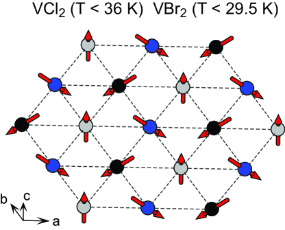
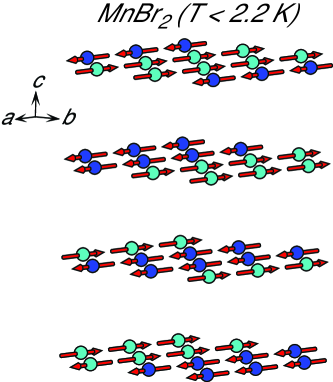
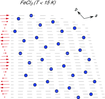
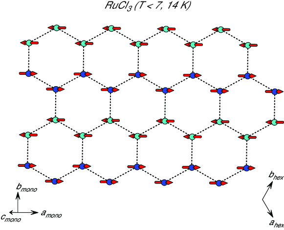
Note that in the figures below showing the magnetic structures of and compounds, only the sublattices are shown. The magnetic moments directions are indicated by red arrows. In addition, to make the magnetic structures easier to view, different colored balls are used to represent atoms with moments along different directions, except for in the more complex helimagnetic structures.
III.1 MX2 Compounds
III.1.1 TiX2 and ZrX2
These compounds have Ti and Zr in the unusual formal oxidation state of 2+. However, as noted above, metal-metal bonds are present in ZrI2, so this simple electron counting is invalid in this case. Divalent Ti and Zr in Ti and ZrCl2 have electron configurations of and , respectively, with an expected spin of . There have been very few magnetic studies of these materials, likely due in part to their instability and reactivity. Magnetic susceptibility measurements on TiCl2 down to 80 K have revealed a cusp near 85 K Lewis et al. (1962). The authors suggest that this may indicate antiferromagnetic ordering at this temperature, although they note that previous measurements showed smoothly increasing susceptibility upon cooling from 300 to 20 K Starr et al. (1940), but this was based on only six temperature points and significant features could have been overlooked. Magnetic susceptibility versus temperature curves have somewhat unusual shapes, and effective moments of 1.1 and 2.0 per Ti have been reported Lewis et al. (1962); Starr et al. (1940). A Weiss temperature of 702 K was determined by Starr et al. Starr et al. (1940), which would indicate strong antiferromagnetic interactions. Frustration of these interactions by the triangular Ti lattice may be responsible for the relatively low ordering temperature of 85 K proposed in Ref. Lewis et al. (1962).
ZrCl2 is reported to have a reduced magnetic moment at room temperature Lewis et al. (1962), but no temperature dependent data were reported. The authors suggest that this may indicate strong antiferromagnetic interactions between Zr magnetic moments. No magnetic structure determinations for TiCl2 were located in the literature and no magnetic information was found for TiBr2 or TiI2.
III.1.2 VX2
These materials contain divalent V with an electronic configuration , . An early report on VCl2 found it to be paramagnetic with a large negative Weiss temperature (565 K) indicating strong antiferromagnetic interactions Starr et al. (1940). Niel et al. later reported Weiss temperatures of 437, 335, and 143 K for VCl2, VBr2, and VI2, respectively, with effective moments close to the expected value of 3.9 , and explained their behavior in terms of a 2D Heisenberg model Niel et al. (1977).
A neutron powder diffraction study showed that all three of the vanadium dihalides order antiferromagnetically with Néel temperatures of 36.0 K for VCl2, 29.5 K for VBr2 and 16.3 K for VI2 Hirakawa et al. (1983). The strong suppression of these ordering temperatures relative to the Weiss temperatures is a result of geometrical frustration. Both temperatures trend to lower values as the halogen is changed from Cl to Br to I. Further neutron scattering experiments revealed that the magnetic order in VCl2 develops in two steps, with phase transition temperatures separated by about 0.1 K, and found the magnetic structure at low temperature to be a 120∘ Néel state shown in Figure 4, where each moment in the triangular lattice is rotated by this angle with respect to its neighbors, with moments in the -plane Kadowaki et al. (1987). The ordered moment corresponded to a spin of 1.2. In that study, three types of critical behavior were observed, corresponding to 2D Heisenberg, 3D Heisenberg, and 3D Ising models. A similar magnetic structure was found for VBr2 with moments of about 83% of the expected value Kadowaki et al. (1985). The magnetic order in VI2 develops in two steps with K and near 15 K, but the low temperature magnetic structure of this compound was not resolved with any certainty Hirakawa et al. (1983).
Recently Abdul Wasey et al. proposed V materials as promising candidates for extending 2D materials beyond graphene and dichalcogenides Abdul Wasey et al. (2013). They report results of first principles calculations of the magnetic order in these systems in both bulk and monolayer forms. In the bulk crystal the experimental spin structure was reproduced. A similar structure is predicted for the monolayer, and the authors suggest that magnetic order in the monolayer may occur at much higher temperature than in the bulk.
III.1.3 MnX2
Divalent Mn has a electronic configuration, with . Magnetization measurements for MnCl2 indicate weak antiferromagnetic interactions ( = 3.3 K) and an effective moment of 5.7 , close to the expected value of 5.9 Starr et al. (1940). Heat capacity measurements indicate magnetic phase transitions at 1.96 and 1.81 K Murray (1962). The magnetic structures of MnCl2 below these two transitions have not been completely determined. Neutron diffraction from single crystals were analyzed assuming a collinear structure and complex orderings with stripes of ferromagnetically aligned spins in the plane were proposed Wilkinson et al. (1958). A more recent investigation of MnCl2-graphite intercalation compounds found that the magnetic order within isolated MnCl2 layers could be described by an incommensurate helimagnetic arrangement, and it was suggested that this may also hold for the magnetic structure of the bulk crystal Wiesler et al. (1995).
A heat capacity anomaly was reported at 2.16 K in MnBr2, and neutron diffraction showed that antiferromagnetic order is present below this temperature Wollan et al. (1958). The magnetic structure has ferromagnetic stripes within the layers with antiferromagnetic coupling between neighboring stripes, as depicted in Figure 5. The moments are along the a axis of the hexagonal cell of the crystal structure. There is antiferromagnetic order between the layers. Later, an incommensurate magnetic phase was identified between this phase and the paramagnetic state, persisting up to about 2.3 K Sato et al. (1995).
MnI2 adopts a complicated helical magnetic structure below 3.4 K Cable et al. (1962a). The moments lie in the (307) planes, and are ferromagnetically aligned within each of these planes. The variation of the moment direction upon moving between (307) planes was originally reported to be a rotation by 2/16 Cable et al. (1962a). Further measurements resolved multiple phase transitions as the magnetic order develops and find the helical ordering to be incommensurate, but with a wave vector close to that reported in the earlier work Sato et al. (1995).
It was recently noted that a ferroelectric polarization develops in the magnetically ordered state of MnI2, spurring interest in this compound as a multiferroic material Kurumaji et al. (2011); Wu et al. (2012). Density functional theory calculations suggest that spin-orbit coupling on the iodine ions is the main source of the ferroelectric polarization in MnI2 Wu et al. (2012), which has been measured to exceed 120 C/m2 Kurumaji et al. (2011). While spin-orbit coupling is required to accurately describe the polarization, is was found to have little influence on the magnetic interactions determined by fitting density functional theory results to a Heisenberg model Wu et al. (2012). In that study it was found that the observed helimagnetic order arises from competing magnetic interactions on the triangular Mn lattice, that electronic correlations, which weaken AFM superexchange, must be considered to accurately reproduce the experimental magnetic structures, and that the details of the spiral structure are sensitive to relatively strong interplane magnetic interactions. The ferroelectric polarization responds to applied magnetic fields in multiferroic MnI2. Magnetic fields affect the polarization by modifying the helimagnetic domain structure at low fields, and by changing the magnetic order at higher fields Kurumaji et al. (2011). Ferroelectric distortions onsetting at the magnetic ordering temperatures and associated multiferroictiy is a common occurrence in compounds that adopt non-collinear magnetic structures (see CoI2, NiBr2, and NiI2 below); however, the details of the coupling between the spin and electric polarization in these and related triangular lattice multiferroics is not well understood Kurumaji et al. (2013).
III.1.4 FeX2
The divalent iron, , in these compounds is expected to be in the high spin state with . The partially filled levels means that orbital angular momentum is not quenched, and an orbital moment may be expected, as discussed in [106] and references therein. Significant anisotropy is observed in the paramagnetic state in all three of the iron dihalides, with a larger effective moment measured along the axis Bertrand et al. (1974). Moments in the magnetically ordered states are also along this direction. Weiss temperatures determined from measurements with the field in the plane () and out of the plane () are 9 K () and 21 K () for FeCl2, 3.0 K () and 3.5 K () for FeBr2, and 24 K () and 21.5 K () for FeI2 Bertrand et al. (1974).
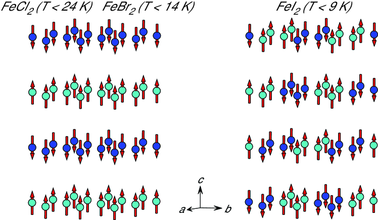
Although the crystallographic structures of FeCl2 and FeBr2 differ (Table 1), they have the same ordered arrangement of spins at low temperature. This magnetic structure is shown in Figure 6, and contains ferromagnetic intralayer order and antiferromagnetic stacking. The chloride orders below 24 K and has an ordered moment of 4.5 Wilkinson et al. (1959), and the bromide orders below 14 K and has an ordered moment of 3.9 Wilkinson et al. (1959); Fert et al. (1973a). The iodide adopts a different low temperature structure below its Néel temperature of 9 K, with two-atom-wide ferromagnetic stipes in the plane (ordered moment of 3.7 ) that are aligned antiferromagnetically with neighboring stripes Gelard et al. (1974). The moment arrangement is shifted from layer to layer so that the magnetic unit cell contains four layers. This is similar to the magnetic structure of MnBr2 shown in Figure 5, but the stripes run in different directions in the plane. There is no apparent correlation between the Weiss temperatures and magnetic ordering temperatures in the Fe series. This is likely related to the presence of both FM and AFM interaction in these materials, which complicates interpretation of the fitted Weiss temperatures.
As noted above, FeCl2 undergoes a transition from the CdCl2 structure to the CdI2 structure at a pressure of 0.6 GPa. At higher pressures two additional phase transitions occur, with pronounced effects on the magnetic behavior. Above 32 GPa the orbital moment is quenched and the magnetic moments cant away from the axis. A further increase in pressure results in the collapse of the magnetization and an insulator-metal transition that is attributed to delocalization of the Fe electrons Xu and Pasternak (2002); Rozenberg et al. (2009). Similar behavior is reported for FeI2 Pasternak et al. (2001). In both materials the Néel temperature in increased with applied pressure, and reaches room temperature before collapsing into the non-magnetic state.
In the antiferromagnetic state, magnetic field induced phase transitions, or metamagnetic transitions, occur in FeCl2, FeBr2, and FeI2 at applied fields near 11, 29, and 46 kOe, respectively Jacobs and Lawrence (1967); Fert et al. (1973a, b) . This arises from stronger ferromagnetic coupling within the layers compared to the weak antiferromagnetic coupling between them, and led to much of the early interest in these materials, as summarized in [114] and references therein. The most complex behavior is seen in FeI2 Fert et al. (1973b). From magnetization and heat capacity measurements, Katsumata et al. identified four different field induced phases, in addition to the antiferromagnetic ground state, and proposed ferrimagnetic structures for them Katsumata et al. (2010). In addition, Binek et al. have proposed the emergence of a Griffith’s phase in FeCl2 Binek and Kleemann (1994); Binek et al. (1996), and neutron diffraction has been used to construct the temperature-field magnetic phase diagram of FeBr2 Katsumata et al. (1997).
III.1.5 CoX2
Cobalt dihalides have cobalt in electronic configuration , which can have a high () or low () spin state. Orbital magnetic moments may be expected in either state. It is apparent from neutron diffraction results that the high spin state is preferred, at least for CoCl2 and CoBr2. The ordered moment on Co in CoCl2 which orders below 25 K Chisholm and Stout (1962), is 3.0 Wilkinson et al. (1959), and it is 2.8 in CoBr2 Wilkinson et al. (1959), which orders at 19 K Yoshizawa et al. (1980). These are close to the expected value of for for high-spin only. However, magnetization measurements on CoCl2 Starr et al. (1940) indicate an enhanced effective moment in the paramagnetic state (5.3 ), which suggests an orbital contribution, and a Weiss temperature of 38 K.
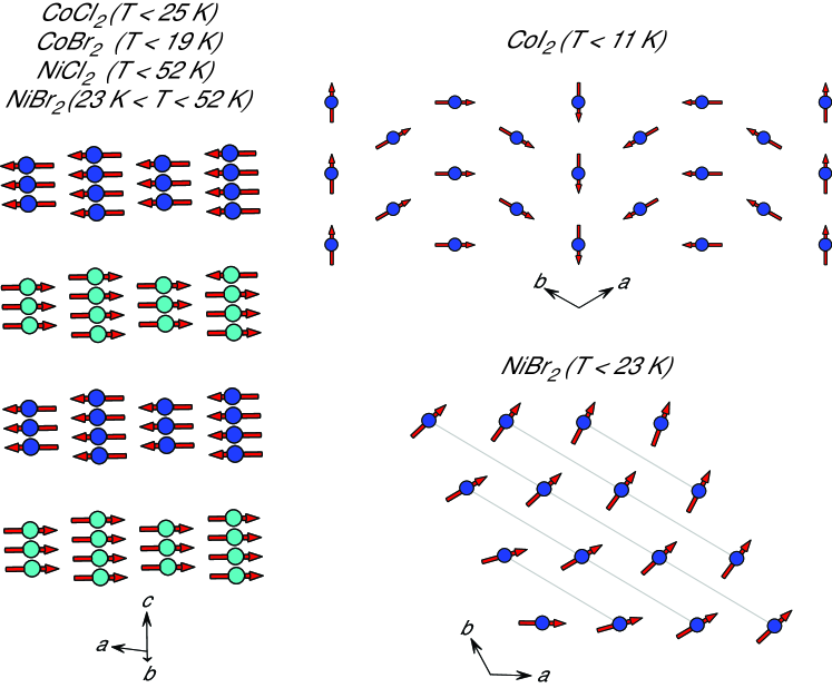
Below their ordering temperatures, both of these compounds adopt the magnetic structure shown in Figure 7, with ferromagnetic alignment within each layer and antiferromagnetic stacking. The moments are known to be parallel or antiparallel to the hexagonal [210] direction for CoCl2 Wilkinson et al. (1959), as shown in the Figure. The moments in CoBr2 are only known to lie within the ab plane Wilkinson et al. (1959).
The magnetic behavior in CoI2 is more complex. CoI2 is a helimagnet with a spiral spin structure, and anisotropic magnetic susceptibility in the paramagnetic state arising from spin-orbit coupling Mekata et al. (1992). Powder neutron diffraction analysis indicated a cycloidal structure with moments in the plane and planes stacked antiferromagnetically Kuindersma et al. (1981), which is supported by Mössbauer spectroscopy Friedt et al. (1976). The corresponding in-plane spin arrangement is shown Figure 7. Mekata et al. used single crystal neutron diffraction to examine the magnetic order in CoI2 and found evidence of a more complicated magnetic structure that requires an additional propagation vector to describe. The same study identified a first order magnetic phase transition at 9.4 K, just below the magnetic ordering transition at 11.0 K, and suggested that these successive transitions may arise due to in-plane magnetic frustration, but no change in the magnetic structure was observed at 9.4 K Mekata et al. (1992).
An electric polarization of about 10 C/m2 that varies with applied magnetic field is induced below the magnetic ordering transition in CoI2 indicating multiferroic behavior Kurumaji et al. (2013) (see MnI2 above, NiBr2, NiI2 below).
III.1.6 NiX2
The octahedrally coordinated, divalent nickel in these compounds has a electronic configuration, with filled and half-filled orbitals. Magnetic moments are expected to be spin only, as orbital angular momentum is quenched in this configuration. Magnetization data for NiCl2 indicate an effective moment of 3.3 , somewhat larger than the spin only value of 2.8 expected for , and Weiss temperature of 68 K, suggesting predominantly ferromagnetic interactions Starr et al. (1940). The Néel temperatures of NiCl2 and NiBr2 are quite similar; upon cooling, both develop long range antiferromagnetic order below 52 K Busey and Giauque (1952); Adam et al. (1980). Their fully ordered moments are 2.11 and 2.0 , respectively De Gunzbourg et al. (1971); Adam et al. (1980), as expected for . The resulting magnetic structure is shown in Figure 7a. The moments lie within the plane and are ferromagnetically aligned within each layer, with antiferromagnetic stacking. The moment directions were determined from Mössbauer spectroscopy to be parallel and antiparallel to the [210] direction, as depicted in the figure Pollard et al. (1982).
While the magnetic structure shown in Figure 7 describes NiCl2 at all temperatures below , NiBr2 undergoes a second phase transition, to a more complicated magnetic structure below 23 K Day et al. (1976); Day and Ziebeck (1980); Adam et al. (1980). Below this first order transition the magnetic moments adopts an incommensurate helimagnetic structure with a periodicity that varies with temperature. As described by Adam et al., the magnetic moments still lie within the basal plane, but vary in direction at 4.2 K by 9.72∘ from site to site along both the hexagonal and axes Adam et al. (1980), as depicted in Figure 7. This results in a periodicity of about 37 crystallographic unit cells along each in-plane direction. The stacking remains antiferromagnetic.
Heat capacity data show that NiI2 undergoes two phase transitions upon cooling, at 75 and 60 K Billery et al. (1977). Helimagnetic order develops at 75 K, and the phase transition at 60 K is crystallographic Kuindersma et al. (1981). The helimagnetic structure of NiI2 is incommensurate with the nuclear structure and the moments rotate in a plane that makes a 55∘ angle with the axis, as depicted in Kuindersma et al. (1981). The ordered moment at 4.2 K was determined to be 1.6 .
Like helimagnetic MnI2 and CoI2 described above, NiBr2 and NiI2 also develop a ferroelectric polarization in their helimagnetic states Tokunaga et al. (2011); Kurumaji et al. (2013). Polarizations of 2025 C/m2 are observed in the bromide, and polarizations exceeding 120 C/m2 are reported for the iodide. As in MnI2 and CoI2, the polarization can be controlled by applied magnetic fields through their influence on the helimagnetic domain structure Tokunaga et al. (2011); Kurumaji et al. (2013).
III.2 MX3 Compounds
Several of the compounds listed in Table 2 are not known to form magnetically ordered states. These include Ti, MoCl3, TcCl3, Rh, and Ir. The later two materials have electron configuration , and are expected to have non-magnetic ground states with all electrons paired. A clue to the non-magnetic nature of MoCl3 Schäfer et al. (1967) is found in the magnetic behavior of TiCl3. Although neutron diffraction shows no magnetic ordering in layered TiCl3 at low temperature, magnetic susceptibility shows a dramatic and sharp decrease near 217 K. This corresponds to the structural distortion noted above in the discussion of TiCl3 and described in [52] and [89]. Ogawa had earlier observed a lattice response coincident with the magnetic anomaly, and proposed that the formation of covalently bonded Ti-Ti dimers that pair the electrons on each Ti as the reason for the collapse of the magnetic moment Ogawa (1960). Thus the strong dimerization in MoCl3 (Table 2) is expected to be responsible for its non-magnetic nature. Dimerized TcCl3 is also expected to be non-magnetic Poineau et al. (2013).
III.2.1 VX3
Little information about magnetic order in VCl3 or VBr3 is available. These compounds are expected to be magnetic due to their electron configuration () and the undistorted honeycomb net of the BiI3 structure type reported for these materials (Table 2). Magnetic susceptibility data Starr et al. (1940) for VCl3 give an effective moment of 2.85 , close to the expected value for (2.82 ), and a Weiss temperature of 30 K, indicating antiferromagnetic interactions. The maximum displayed near 20 K in the temperature dependence of the susceptibility suggests antiferromagnetic order at lower temperatures. First principles calculations have been done to examine the electronic and magnetic properties of monolayers of VCl3 and (hypothetical) VI3 Zhou et al. (2016); He et al. (2016). Both are predicted to be ferromagnetic.
III.2.2 CrX3
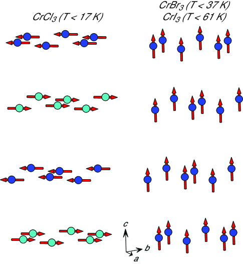
In these compounds Cr is expected to be in a electronic configuration, and effective moments determined from high temperature magnetic susceptibility range from 3.7 to 3.9 per Cr as expected for Starr et al. (1940); Tsubokawa (1960); McGuire et al. (2015). Weiss temperatures determined from these measurements are 27, 47, and 70 K for CrCl3, CrBr3, and CrI3, respectively, indicating predominantly ferromagnetic interactions. In fact, among the layered and materials, the chromium trihalide family contains the only compounds in which long-range, 3D ferromagnetic ground states are observed. The magnetic structures are shown in Figure 8. Below 61 K for CrI3 and 37 K for CrBr3, moments directed out of the plane order ferromagnetically Hansen (1959); Tsubokawa (1960); Dillon Jr. and Olson (1965); McGuire et al. (2015). In CrCl3 below about 17 K, ferromagnetic order is also observed within the layers, but the layers stack antiferromagnetically Cable et al. (1961); Kuhlow (1982). Also unlike the tribromide and triiodide, the moments in CrCl3 lie within the planes. In this series, the ordering temperatures scale nicely with the Weiss temperatures. The ordered moments determined by neutron diffraction and magnetic saturation are all close to 3 as expected for the electronic configuration of Cr3+. Reported values are 2.7–3.2 for CrCl3 Cable et al. (1961), 3 for CrBr3 Tsubokawa (1960), and 3.1 for CrI3 McGuire et al. (2015); Dillon Jr. and Olson (1965). Significant magnetic anisotropy is observed in the ferromagnetic state of CrI3; the anisotropy field, the field required to rotate the ordered moments away from the -axis and into the -plane, is found to be near 30 kOe near 2 K McGuire et al. (2015); Dillon Jr. and Olson (1965). Ferromagnetic CrBr3 has a significantly lower anisotropy field of about 5 kOe Hansen (1959); Tsubokawa (1960).
With moments in the plane and antiferromagnetic stacking of the layers CrCl3 is unique among the chromium trihalides. It also has weak magnetic anisotropy. A magnetic field of only a few kOe is sufficient to overcome the antiferromagnetic order and fully polarize the magnetization in any direction Cable et al. (1961); Kuhlow (1982). Using the optical technique of Faraday rotation, Kuhlow followed closely the evolution of the magnetization in CrCl3 with changing temperature and applied magnetic field Kuhlow (1982). It was noted that the magnetic order appears to onset in two stages upon cooling, first developing ferromagnetic correlations and 16.7 K with long range antiferromagnetic order as shown in Figure 8 below 15.5 K.
The ferromagnetism in these Cr compounds makes them particulary interesting for incorporating magnetism into functional van der Waals heterostructures. Several relevant theoretical studies have been reported that suggest ferromagnetic order may persist into monolayer specimens Wang et al. (2011); McGuire et al. (2015); Liu et al. (2016); Zhang et al. (2015) . Recently ferromagnetic monolayers of CrI3 were demonstrated experimentally Huang et al. (2017). Ferromagnetic CrI3 was also recently incorporated into a van der Waals heterostructure in which an exchange field effect equivalent to a 13 T applied magnetic field was observed in the electronic properties of monolayer WSe2 when the heterostructure was cooled through the Curie temperature of CrI3 Zhong et al. (2017). Although CrCl3 has an antiferromagnetic structure in the bulk, each layer is ferromagnetically ordered. If this proves to be independent of sample thickness then ferromagnetic monolayers may be realized in all three of the chromium trihalides, with a range of magnetic anisotropy that may allow easy tuning of the magnetization direction in the chloride or more robust moment orientation in the iodide.
III.2.3 FeX3
FeCl3 and FeBr3 have iron in the configuration. There has been considerable study of the magnetism in the chloride, but very little for the bromide. Early magnetization measurements on FeCl3 found an effective moment of 5.7 , close to the expected spin-only value of 5.9 , and a Weiss temperature of 11.5 K, indicating antiferromagnetic interactions Starr et al. (1940). A neutron diffraction study found a helimagnetic structure for FeCl3 below about 15 K, with an ordered moment on 4.3 per iron at 4.2 K Cable et al. (1962b). The reduction from the expected value of 5 may be due to some disorder still present at 4.2 K or could arise from a slight distortion from the periodic model used to describe the magnetic order. Later magnetization measurements place the Néel temperature at 9–10 K Jones Jr. et al. (1969); Johnson et al. (1981).
The magnetic structure of FeCl3 is shown in Figure 9. The figure shows one layer of Fe atoms, with dashed lines denoting (140) planes. Sites in this layer on a common (140) plane have parallel moments with their orientation indicated at the left of the Figure. Note that the moments all have the same magnitude, but their projections on to the plane of the page vary as their orientations rotate about the [140] direction by 2/15 between neighboring planes Cable et al. (1962b). The layers stack antiferromagnetically. A field induced magnetic phase transition was noted in FeCl3 by Stampfel et al. and Johnson et al. with the magnetic structure evolving with field up to about 15 kOe and experiencing a spin-flop near 40 kOe Stampfel et al. (1973); Johnson et al. (1981) . A Mössbauer spectroscopy study of FeBr3 found magnetic order below 15.7 K, and the authors proposed the order below this temperature to be antiferromagnetic in analogy with FeCl3 Oosterhuis et al. (1975).
III.2.4 RuX3
Recent interest in RuCl3 began with Plumb et al. identifying it as a spin-orbit assisted Mott insulator in which a small band gap arises from a combination of spin-orbit interactions and strong electron-electron correlations Plumb et al. (2014). In this compound, Ru has electron configuration . Considering spin only gives an option of a high spin configuration () with all and levels half filled, or a lower spin configurations with some levels doubly occupied. In this case the crystal field splitting is large enough so that all five of the electrons go into the lower, set leaving only one unpaired spin (). However, the orbital angular momentum is not quenched and cannot be neglected. In addition, the spin orbit coupling interaction, which increases in strength as where is the atomic number of the nucleus, must also be considered for this heavy, transition metal. In RuCl3, spin orbit coupling, along with significant electron-electron correlations, splits the otherwise degenerate states into states with effective angular momentum and Kim et al. (2008, 2015). The states are lower in energy, and hold four of the five electrons, leaving one for the higher energy level, and giving Ru in this compound an angular momentum of . Magnetization measurements in the paramagnetic state have been reported for both powder and single crystals. Powder measurements give effective moments of 2.2–2.3 and Weiss temperatures of 23–40 K Fletcher et al. (1963, 1967); Kobayashi et al. (1992); Banerjee et al. (2016). Single crystal measurements show strong paramagnetic anisotropy, and give = 2.1 and = 37 K with the field applied in the plane, and = 2.7 and = 150 K with the field applied perpendicular to the layers Majumder et al. (2015).
Two magnetic phase transitions have been observed in RuCl3, at 14 K and 7 K. It is believed that the difference depends upon the details of the stacking sequence of the RuCl3 layers and the density of stacking faults Banerjee et al. (2016). Some crystals show only one transition or the other, while others samples show both. In crystals which undergo no crystallographic phase transition upon cooling (see above) and remain monoclinic at all temperatures magnetic order occurs below 14 K, while crystals that undergo a structural transition upon cooling show only the 7 K transition Banerjee et al. (2016); Park et al. (2016). Pristine crystals that have shown a phase transition at 7 K can be transformed into crystals with only the 14 K transition through mechanical deformation Banerjee et al. (2016); Cao et al. (2016). Although all of the details of the magnetic structures of the two phases are have not been settled, there is consensus that the in-plane magnetic structures are of the so-called zig-zag type Sears et al. (2015); Johnson et al. (2015); Banerjee et al. (2016); Cao et al. (2016) shown in Figure 10. Determinations of the size of the ordered moment include 0.4 Banerjee et al. (2016), 0.45 Cao et al. (2016), 0.64 Johnson et al. (2015), and 0.73 Park et al. (2016). The moment direction is reported to lie in the monoclinic -plane, with components both in and out of the plane of the RuCl3 layers Johnson et al. (2015); Cao et al. (2016); Park et al. (2016). The layers stack antiferromagnetically with a different stacking sequence associated with the different transition temperatures. AB magnetic stacking is seen in crystals with a 14 K transition, ABC stacking is seen in crystals with a 7 K transition, and both types of stacking onsetting at the appropriate temperatures are seen in samples with both transitions Johnson et al. (2015); Banerjee et al. (2016); Cao et al. (2016).
With and strong spin orbit coupling on a honeycomb lattice, RuCl3 is identified as a promising system for studying the Kitaev model Kitaev (2006); Plumb et al. (2014); Kim et al. (2015). In this model, anisotropic interactions result in a type of magnetic frustration. This can give rise to a quantum spin liquid ground state, in which fluctuations prevent magnetic order even at very low temperature, and in which particulary exotic magnetic excitations are predicted Baskaran et al. (2007); Knolle et al. (2014); Banerjee et al. (2016). This is, in fact, the motivation for much of the current interest in RuCl3.
IV Summary and Conclusions
The binary transition-metal halides and reviewed here have simple layered crystal structures containing triangular and honeycomb transition metal nets, yet they display a wide variety of interesting crystallographic and magnetic behaviors. Several compounds display polymorphism, with multiple layered and non-layered structures reported. Temperature and pressure induced crystallographic phase transitions are observed in some. Dimerization of transition metal cations results in a quenching of the magnetic moment in materials like Ti and MoCl3. All of the materials which maintain a local magnetic moment are observed to order magnetically, although the magnetic order in TiCl2 is not definitively confirmed. This compound and the vanadium dihalides clearly show evidence of geometrical frustration of strong antiferromagnetic interactions on their triangular lattices, with ordering temperatures an order of magnitude smaller than their Weiss temperatures. Effects of a different kind of frustration, due to competing anisotropic exchange interactions, is observed in RuCl3, making it a promising candidate for the realization of a Kitaev spin liquid. It appears that the in-plane magnetic interactions are at least partly ferromagnetic in most of the other magnetic and compounds, and field induced phase transitions that may arise from competing magnetic interactions and multiple low energy magnetic configurations are observed in several of cases. Several dihalides adopt helimagnetic structures and develop electric polarization at their magnetic ordering temperature, providing an interesting class of multiferroic materials. Finally, interest is growing in producing monolayer magnetic materials from several of these compounds, in particular the chromium trihalides, which will enable exciting advances in functional van der Waals heterostructures. Particularly interesting for this application is the wide variety of in-plane magnetic structures that occur in and compounds. Although several of these materials have been studied for many decades, it is likely that layered, binary, transition-metal halides will continue to provide a fruitful playground for solid state chemists, physicists, and materials scientists seeking to further our understanding of low dimensional magnetism and to develop new functional materials.
Acknowledgments
This work is supported by the US Department of Energy, Office of Science, Basic Energy Sciences, Materials Sciences and Engineering Division.
References
- de Jongh (1990) L. J. de Jongh, Magnetic Properties of Layered Transition Metal Compounds (Kluwer Academic Press: Dordrecht, The Netherlands, 1990).
- Kadowaki et al. (1987) H. Kadowaki, K. Ubukoshi, K. Hirakawa, J. L. Martinez, and G. Shirane, J. Phys. Soc. Japan 56, 4027 (1987).
- Ramirez (1994) A. P. Ramirez, Annu. Rev. Mater. Sci. 24, 453 (1994).
- Collins and Petrenko (1997) M. F. Collins and O. A. Petrenko, Can. J. Phys. 75, 605 (1997).
- Tokunaga et al. (2011) Y. Tokunaga, D. Okuyama, T. Kurumaji, T. Arima, H. Nakao, Y. Murakami, Y. Taguchi, and Y. Tokura, Phys. Rev. B 84, 060406(R) (2011).
- Kurumaji et al. (2011) T. Kurumaji, S. Seki, S. Ishiwata, H. Murakawa, Y. Tokunaga, Y. Kaneko, and Y. Tokura, Phys. Rev. Lett. 106, 167206 (2011).
- Wu et al. (2012) X. Wu, Y. Cai, Q. Xie, H. Weng, H. Fan, and J. Hu, Phys. Rev. B 86, 134413 (2012).
- Kurumaji et al. (2013) T. Kurumaji, S. Seki, S. Ishiwata, H. Murakawa, Y. Kaneko, and Y. Tokura, Phys. Rev. B 87, 014429 (2013).
- Plumb et al. (2014) K. W. Plumb, J. P. Clancy, L. J. Sandilands, V. V. Shankar, Y. F. Hu, K. S. Burch, H.-Y. Kee, and Y.-J. Kim, Phys. Rev. B 90, 041112 (2014).
- Kim et al. (2015) H. Kim, V. Shankar V., A. Catuneanu, and H. Kee, Phys. Rev. B 91, 241110(R) (2015).
- Sears et al. (2015) J. A. Sears, M. Songvilay, K. W. Plumb, J. P. Clancy, Y. Qiu, Y. Zhao, D. Parshall, and Y. J. Kim, Phys. Rev. B 91, 144420 (2015).
- Johnson et al. (2015) R. D. Johnson, S. C. Williams, A. A. Haghighirad, J. Singleton, V. Zapf, P. Manuel, I. I. Mazin, Y. Li, H. O. Jeschke, R. Valenti, and R. Coldea, Phys. Rev. B 92, 235119 (2015).
- Banerjee et al. (2016) A. Banerjee, C. A. Bridges, J. Q. Yan, A. A. Aczel, L. Li, M. B. Stone, G. E. Granroth, M. D. Lumsden, Y. Yiu, J. Knolle, S. Bhattacharjee, D. L. Kovrizhin, R. Moessner, D. A. Tennant, D. G. Mandrus, and S. E. Nagler, Nature Materials 15, 733 (2016).
- Geim and Geigorieva (2013) A. K. Geim and I. V. Geigorieva, Nature 499, 419 (2013).
- Wang et al. (2011) H. Wang, V. Eyert, and U. Schwingenschlögl, J. Phys. Condens. Matter 23, 116003 (2011).
- McGuire et al. (2015) M. A. McGuire, H. Dixit, V. R. Cooper, and B. C. Sales, Chem. Mater. 27, 612 (2015).
- Zhang et al. (2015) W.-B. Zhang, Q. Qu, P. Zhu, and C.-H. Lam, J. Mater. Chem. C 3, 12457 (2015).
- Liu et al. (2016) J. Liu, Q. Sun, Y. Kawazoe, and P. Jena, Plys. Chem. Chem. Phys. 18, 8777 (2016).
- Wang et al. (2016) H. Wang, F. Fan, S. Zhu, and H. Wu, EPL 114, 47001 (2016).
- Zhong et al. (2017) D. Zhong, K. L. Seyler, X. Linpeng, R. Cheng, N. Sivadas, B. H. E. Schmidgall, T. Taniguchi, K. Watanabe, M. A. McGuire, W. Yao, D. Xiao, K.-M. C. Fu, and X. Xu, arXiv:1704.00841 (2017).
- Huang et al. (2017) B. Huang, G. Clark, E. Navarro-Moratalla, D. R. Klein, R. Cheng, K. L. Seyler, D. Zhong, E. Schmidgall, M. A. McGuire, D. H. Cobden, W. Yao, D. Xiao, P. Jarillo-Herrero, and X. Xu, arXiv:1703.05892 (2017).
- Lebègue et al. (2013) S. Lebègue, T. Björkman, M. Klintenberg, R. M. Nieminen, and O. Eriksson, Phys. Rev. X 3, 031002 (2013).
- Ajayan et al. (2016) P. Ajayan, P. Kim, and K. Banerjee, Phys. Today 69, 38 (2016).
- Park (2016) J. Park, J. Phys.: Condens. Matter 28, 301001 (2016).
- MacDonald and Tsoi (2011) A. H. MacDonald and M. Tsoi, Phil. Trans. R. Soc. A 369, 3098 (2011).
- Gomonay and Loktev (2014) E. V. Gomonay and V. M. Loktev, Low Temp. Phys. 40, 17 (2014).
- Jungwirth et al. (2016) T. Jungwirth, X. Marti, P. Wadley, and J. Wunderlich, Nature Nanotechnology 11, 231 (2016).
- Klemm and Krose (1947) W. Klemm and E. Krose, Z. Anorg. Chem. 253, 218 (1947).
- Natta et al. (1961) G. Natta, P. Corradini, and G. Allegra, J. Polymer Sci. 51, 399 (1961).
- von Schnering et al. (1961) H. G. von Schnering, H. Wöhrle, and H. Schäfer, Naturwissensch. 48, 159 (1961).
- Sheckelton et al. (2017) J. P. Sheckelton, K. W. Plumb, B. A. Trump, C. L. Broholm, and T. M. McQueen, Inorg. Chem. Front. 4, 481 (2017).
- Jiang et al. (2017) J. Jiang, Q. Liang, R. Meng, Q. Yang, C. Tan, X. Sun, and X. Chen, Nanoscale 9, 2992 (2017).
- Baenziger and Rundle (1948) N. C. Baenziger and R. E. Rundle, Acta Crystallogr. 1, 274 (1948).
- Ehrlich et al. (1961) P. Ehrlich, W. Gutsche, and H. J. Seifert, Z. Anorg. Allg. Chem. 312, 80 (1961).
- Klemm and Grimm (1942) W. Klemm and L. Grimm, Z. Anorg. Allg. Chem. 249, 198 (1942).
- Villadsen (1959) J. Villadsen, Acta Chem. Scand. 13, 2146 (1959).
- Kuindersma et al. (1979) S. R. Kuindersma, C. Hass, J. P. Sanchez, and R. Al, Solid State Commun. 30, 403 (1979).
- Tornero and Fayos (1990) J. D. Tornero and J. Fayos, Z. Kristallogr. 192, 147 (1990).
- Wollan et al. (1958) E. O. Wollan, W. C. Koehler, and M. K. Wilkinson, Phys. Rev. 110, 638 (1958).
- Ferrari and Giorgi (1929a) A. Ferrari and F. Giorgi, Atti Accad. Naz. Lincei, Cl. Sci. Fis., Mat. Nat., Rend. 10, 522 (1929a).
- Vettier and Yellon (1975) C. Vettier and W. B. Yellon, J. Phys. Chem. Solids 36, 401 (1975).
- Haberecht et al. (2001) J. Haberecht, H. Borrmann, and R. Kniep, Z. Kristallogr. - New Cryst. Struct. 216, 210 (2001).
- Gelard et al. (1974) J. Gelard, A. R. Fert, P. Mériel, and Y. Allain, Solid State Commun. 14, 187 (1974).
- Grimme and Santos (1934) H. Grimme and J. A. Santos, Z. Kristallogr. 88, 136 (1934).
- Ferrari and Giorgi (1929b) A. Ferrari and F. Giorgi, Atti Accad. Naz. Lincei, Cl. Sci. Fis., Mat. Nat., Rend. 9, 1134 (1929b).
- Ferrari et al. (1963) A. Ferrari, A. Braibanti, and G. Bigliardi, Acta Crystallogr. 16, 846 (1963).
- Nasser et al. (1992) J. A. Nasser, J. M. Kiat, and R. Gabilly, Solid State Commun. 82, 49 (1992).
- Ketalaar (1934) J. A. A. Ketalaar, Z. Kristallogr. 88, 26 (1934).
- Cisar et al. (1979) A. Cisar, J. D. Corbett, and R. L. Daake, Inorg. Chem. 18, 836 (1979).
- Guthrie and Corbett (1981) D. H. Guthrie and J. D. Corbett, J. Solid State Chem. 37, 256 (1981).
- Corbett and Guthrie (1982) J. D. Corbett and D. H. Guthrie, Inorg. Chem. 21, 1747 (1982).
- Troyanov et al. (1991) S. I. Troyanov, E. M. Snigireva, and V. B. Rybakov, Russ. J. Inorg. Chem. 36, 634 (1991).
- Troyanov et al. (1990) S. I. Troyanov, V. B. Rybakov, and V. M. Ionov, Russ. J. Inorg. Chem. 35, 494 (1990).
- McCarley et al. (1964) R. E. McCarley, J. W. Roddy, and K. O. Berry, Inorg. Chem. 3, 50 (1964).
- Morosin and Narath (1964) B. Morosin and A. Narath, J. Chem. Phys. 40, 1958 (1964).
- Handy and Gregory (1952) L. L. Handy and N. W. Gregory, J. Am. Chem. Soc. 74, 891 (1952).
- Hashimoto et al. (1989) S. Hashimoto, K. Forster, and S. C. Moss, J. Appl. Crystallogr. 22, 173 (1989).
- Troyanov (1993) S. Troyanov, Russ. J. Inorg. Chem. 38, 1821 (1993).
- Armbrüster et al. (2000) M. Armbrüster, T. Ludwig, H. W. Rotter, G. Thiele, and H. Oppermann, Z. Anorg. Allg. Chem. 626, 187 (2000).
- Schäfer et al. (1967) H. Schäfer, H. G. von Schnering, J. V. Tillack, F. Kuhnen, H. Wörle, and H. Baumann, Z. Anorg. Allgem. Chem. 353, 281 (1967).
- Poineau et al. (2012) F. Poineau, E. V. Johnstone, P. F. Weck, P. M. Forster, E. Kim, K. R. Czerwinski, and A. P. Sattelberger, Inorg. Chem. 51, 4915 (2012).
- Cao et al. (2016) H. B. Cao, A. Banerjee, J. Yan, C. A. Bridges, M. D. Lumsden, D. G. Mandrus, D. A. Tennant, B. C. Chakoumakos, and S. E. Nagler, Phys. Rev. B 93, 134423 (2016).
- Fletcher et al. (1967) J. M. Fletcher, W. E. Gardner, A. C. Fox, and G. Topping, J. Chem. Soc. A , 1038 (1967).
- Stroganov and Ovchinnikov (1957) E. V. Stroganov and K. V. Ovchinnikov, Vestn. Leningr. Univ., Ser. 4 22, 152 (1957).
- Bärnighausen and Handa (1964) H. Bärnighausen and B. K. Handa, J. Less-Common Met. 6, 226 (1964).
- Brodersen et al. (1968a) K. Brodersen, G. Thiele, and I. Recke, J. Less-Common Met. 14, 151 (1968a).
- Brodersen et al. (1965) K. Brodersen, F. Moers, and H. G. von Schnering, Naturwissensch. 52, 205 (1965).
- Brodersen et al. (1968b) K. Brodersen, G. Thiele, H. Ohnsorge, I. Recke, and F. Moers, J. Less-Common Met. 15, 347 (1968b).
- Brehzer (1959) B. Brehzer, Naturwissenschaften 46, 106b (1959).
- Yamaguchi (1942a) S. Yamaguchi, Sci. Pap. Inst. Phys. Chem. Res. (Jpn.) 39, 291 (1942a).
- Yamaguchi (1942b) S. Yamaguchi, Sci. Pap. Inst. Phys. Chem. Res. (Jpn.) 39, 357 (1942b).
- Pauling (1929) L. Pauling, Proc. Natl. Acad. Sci. U.S.A. 15, 709 (1929).
- Mitchell (1962) R. S. Mitchell, Z. Kristallogr. 117, 309 (1962).
- Bozorth (1922) R. M. Bozorth, J. Am. Chem. Soc. 44, 2232 (1922).
- Bijvoet et al. (1926) J. M. Bijvoet, A. Claassen, and A. Karssen, Proc. K. Ned. Akad. Wet. 29, 529 (1926).
- Schneider et al. (1992) M. Schneider, P. Kuske, and H. D. Lutz, Acta Crystallogr. B 48, 761 (1992).
- Kuindersma et al. (1981) S. R. Kuindersma, J. P. Sanchez, and C. Haas, Phys. B Condens. Matter 111, 231 (1981).
- Narath and Schirber (1966) A. Narath and J. E. Schirber, J. Appl. Phys. 37, 1124 (1966).
- Rozenberg et al. (2009) G. K. Rozenberg, M. P. Pasternak, P. Gorodetsky, W. M. Xu, L. S. Dubrovinsky, T. LeBihan, and R. D. Taylor, Phys. Rev. B 79, 214105 (2009).
- Imoto et al. (1981) H. Imoto, J. D. Corbett, and A. Cisar, Inorg. Chem. 20, 145 (1981).
- Men’kov and Komissarova (1964a) A. A. Men’kov and L. N. Komissarova, Russ. J. Inorg. Chem. 9, 952 (1964a).
- Men’kov and Komissarova (1964b) A. A. Men’kov and L. N. Komissarova, Russ. J. Inorg. Chem. 9, 425 (1964b).
- Templeton and Darter (1954) D. H. Templeton and G. F. Darter, J. Phys. Chem. 58, 940 (1954).
- Brown et al. (1968) D. Brown, S. Fletcher, and D. G. Holah, J. Chem. Soc. A , 1889 (1968).
- Jongen and Meyer (2005) L. Jongen and G. Meyer, Acta Crystallogr. E 61, i151 (2005).
- Poineau et al. (2013) F. Poineau, E. V. Johnstone, K. R. Czerwinski, and A. P. Sattelberger, Accounts of Chemical Research 47, 624 (2013).
- Ogawa (1960) S. Ogawa, J. Phys. Soc. Japan 15, 1901 (1960).
- Troyanov et al. (1994) S. I. Troyanov, E. M. Snigireva, A. P. Pirarevskii, A. I. Yanovskii, and Y. T. Struchkov, Russ. J. Inorg. Chem. 39, 360 (1994).
- Troyanov and Snigireva (2000) S. I. Troyanov and E. M. Snigireva, Russ. J. Inorg. Chem. 45, 580 (2000).
- Park et al. (2016) S.-Y. Park, S.-H. Do, K.-Y. Choi, D. Jang, T.-H. Jang, J. Schefer, C.-M. Wu, J. S. Gardner, J. M. S. Park, J.-H. Park, and S. Ji, arXiv:1609.05690 (2016).
- Babel and Deigner (1965) D. Babel and P. Deigner, Z. Anorg. Allg. Chem. 339, 57 (1965).
- Kim and Kee (2016) H.-S. Kim and H.-Y. Kee, Phys. Rev. B 93, 155143 (2016).
- Zhou et al. (2016) Y. Zhou, H. Lu, X. Zu, and F. Gao, Scientific Reports 6, 19407 (2016).
- Khomskii (2014) D. I. Khomskii, Transition Metal Compounds (Cambridge University Press, 2014).
- Niel et al. (1977) M. Niel, C. Cros, G. Le Flem, M. Pouchard, and P. Hagenmuller, Phys. B Condens. Matter 86-88, 702 (1977).
- Lewis et al. (1962) J. Lewis, D. J. Machin, I. E. Newnham, and R. S. Nyholm, J. Chem Soc. , 2036 (1962).
- Starr et al. (1940) C. Starr, R. Bitter, and A. R. Kaufmann, Phys. Rev. 58, 977 (1940).
- Hirakawa et al. (1983) K. Hirakawa, H. Kadowaki, and K. Ubukoshi, J. Phys. Soc. Japan 52, 1814 (1983).
- Kadowaki et al. (1985) H. Kadowaki, K. Ubukoshi, and K. Hirakawa, J. Phys. Soc. Japan 54, 363 (1985).
- Abdul Wasey et al. (2013) A. H. M. Abdul Wasey, D. Karmakar, and G. P. Das, J. Phys.: Condens. Matter 25, 476001 (2013).
- Murray (1962) R. B. Murray, Phys. Rev. 128, 1570 (1962).
- Wilkinson et al. (1958) M. K. Wilkinson, J. W. Cable, E. O. Wollan, and W. C. Koehler, Oak Ridge National Laboratory Report ORNL-2430, 65 (1958).
- Wiesler et al. (1995) D. G. Wiesler, M. Suzuki, I. S. Suzuki, and N. Rosov, Phys. Rev. Lett. 75, 942 (1995).
- Sato et al. (1995) T. Sato, H. Kadowaki, and K. Iio, Phys. B Condens. Matter 213-214, 224 (1995).
- Cable et al. (1962a) J. W. Cable, M. K. Wilkinson, E. O. Wollan, and W. C. Koehler, Phys. Rev. 125, 1860 (1962a).
- Katsumata et al. (2010) K. Katsumata, H. Aruga Katori, S. Kimura, Y. Narumi, M. Hagiwara, and K. Kindo, Phys. Rev. B 82, 104402 (2010).
- Bertrand et al. (1974) Y. Bertrand, A. R. Fert, and J. Gélard, J. Physique 35, 385 (1974).
- Wilkinson et al. (1959) M. K. Wilkinson, J. W. Cable, E. O. Wollan, and W. C. Koehler, Phys. Rev. 113, 497 (1959).
- Fert et al. (1973a) A. R. Fert, P. Carrara, M. C. Lanusse, G. Mischler, and J. P. Redoules, J. Phys. Chem. Solids 34, 223 (1973a).
- Xu and Pasternak (2002) W. M. Xu and M. P. Pasternak, Hyperfine Interactions 144/145, 175 (2002).
- Pasternak et al. (2001) M. P. Pasternak, W. M. Xu, G. K. Rozenberg, R. D. Taylor, G. R. Hearne, and E. Sterer, Phys. Rev. B 65, 035106 (2001).
- Jacobs and Lawrence (1967) I. S. Jacobs and P. E. Lawrence, Phys. Rev. 164, 866 (1967).
- Fert et al. (1973b) A. R. Fert, J. Gelard, and P. Carrara, Solid State Commun. 13, 1219 (1973b).
- Lines (1963) M. E. Lines, Phys. Rev. 131, 546 (1963).
- Binek and Kleemann (1994) C. Binek and W. Kleemann, Phys. Rev. Lett. 72, 1287 (1994).
- Binek et al. (1996) C. Binek, D. Bertrand, L. P. Regnault, and W. Kleemann, Phys. Rev. B 54, 9015 (1996).
- Katsumata et al. (1997) K. Katsumata, H. Aruga Katori, S. M. Shapiro, and G. Shirane, Phys. Rev. B 55, 11466 (1997).
- Chisholm and Stout (1962) R. C. Chisholm and J. W. Stout, J. Chem. Phys. 36, 972 (1962).
- Yoshizawa et al. (1980) H. Yoshizawa, K. Ubukoshi, and K. Hirakawa, J. Phys. Soc. Japan 48, 42 (1980).
- Mekata et al. (1992) M. Mekata, H. Kuriyama, Y. Ajiro, S. Mitsuda, and H. Yoshizawa, J. Magn. Magn. Mater. 104-107, 859 (1992).
- Friedt et al. (1976) J. M. Friedt, J. P. Sanchez, and G. K. Shenoy, J. Chem. Phys. 65, 5093 (1976).
- Busey and Giauque (1952) R. H. Busey and W. F. Giauque, J. Am. Chem. Soc. 74, 4443 (1952).
- Adam et al. (1980) A. Adam, D. Billery, C. Terrier, R. Mainard, L. P. Regnault, J. Rossat-Mignod, and P. Mériel, Solid State Commun. 35, 1 (1980).
- De Gunzbourg et al. (1971) J. De Gunzbourg, S. Papassimacopoulos, A. Miedan-Gros, and Y. Allain, J. Phys. Colloq. 32, C1 (1971).
- Pollard et al. (1982) R. J. Pollard, V. H. McCann, and J. B. Ward, J. Phys. C: Solid State Phys. 15, 6807 (1982).
- Day et al. (1976) P. Day, A. Dinsdale, E. R. Krausz, and D. J. Robbins, J. Phys. C: Solid State Phys. 9, 2481 (1976).
- Day and Ziebeck (1980) P. Day and K. R. A. Ziebeck, J. Phys. C: Solid State Phys. 13, L523 (1980).
- Billery et al. (1977) D. Billery, C. Terrier, N. Ciret, and J. Kleinclauss, Phys. Lett. A 61, 138 (1977).
- He et al. (2016) J. He, S. Ma, P. Lyu, and P. Nachtigall, J. Mater. Chem. C 4, 2518 (2016).
- Tsubokawa (1960) I. Tsubokawa, J. Phys. Soc. Japan 15, 1664 (1960).
- Hansen (1959) W. N. Hansen, J. Appl. Phys. 30, S304 (1959).
- Dillon Jr. and Olson (1965) J. F. Dillon Jr. and C. E. Olson, J. Appl. Phys. 36, 1259 (1965).
- Cable et al. (1961) J. W. Cable, M. K. Wilkinson, and E. O. Wollan, J. Phys. Chem. Solids 19, 29 (1961).
- Kuhlow (1982) B. Kuhlow, Phys. Stat. Sol. A 72, 161 (1982).
- Cable et al. (1962b) J. W. Cable, M. K. Wilkinson, E. O. Wollan, and W. C. Koehler, Phys. Rev. 127, 714 (1962b).
- Jones Jr. et al. (1969) E. R. Jones Jr., O. B. Morton, L. Cathey, T. Auel, and E. L. Amma, J. Chem. Phys. 50, 4755 (1969).
- Johnson et al. (1981) P. B. Johnson, S. A. Friedberg, and J. A. Rayne, J. Appl. Phys. 52, 1932 (1981).
- Stampfel et al. (1973) J. P. Stampfel, W. T. Oosterhuis, B. Window, and Barros, F. deS, Phys. Rev. B 8, 4371 (1973).
- Oosterhuis et al. (1975) W. T. Oosterhuis, B. Window, and K. Spartalian, Phys. Rev. B 10, 4616 (1975).
- Kim et al. (2008) B. J. Kim, H. Jin, S. J. Moon, J. Y. Kim, B. G. Park, C. S. Leem, J. Yu, T. W. Noh, C. Kim, S. J. Oh, J. H. Park, V. Durairaj, G. Cao, and E. Rotenberg, Phys. Rev. Lett. 101, 076402 (2008).
- Fletcher et al. (1963) J. M. Fletcher, W. E. Gardner, E. W. Hooper, K. R. Hyde, F. H. Moore, and J. L. Woodhead, Nature 199, 1089 (1963).
- Kobayashi et al. (1992) Y. Kobayashi, T. Okada, K. Asai, M. Katada, H. Sano, and F. Ambe, Inorg. Chem. 31, 4570 (1992).
- Majumder et al. (2015) M. Majumder, M. Schmidt, H. Rosner, A. A. Tsirlin, H. Yasuoka, and M. Baenitz, Phys. Rev. B 91, 180401 (2015).
- Kitaev (2006) A. Kitaev, Ann. Phys. 321, 2 (2006).
- Baskaran et al. (2007) G. Baskaran, S. Mandal, and R. Shankar, Phys. Rev. Lett. 98, 247201 (2007).
- Knolle et al. (2014) J. Knolle, D. L. Kovrizhin, J. T. Chalker, and R. Moessner, Phys. Rev. Lett. 112, 207203 (2014).