Migration reversal of soft particles in vertical flows
Abstract
Non-neutrally buoyant soft particles in vertical microflows are investigated. We find, soft particles lighter than the liquid migrate to off-center streamlines in a downward Poiseuille flow (buoyancy-force antiparallel to flow). In contrast, heavy soft particles migrate to the center of the downward (and vanishing) Poiseuille flow. A reversal of the flow direction causes in both cases a reversal of the migration direction, i. e. heavier (lighter) particles migrate away from (to) the center of a parabolic flow profile. Non-neutrally buoyant particles migrate also in a linear shear flow across the parallel streamlines: heavy (light) particles migrate along (antiparallel to) the local shear gradient. This surprising, flow-dependent migration is characterized by simulations and analytical calculations for small particle deformations, confirming our plausible explanation of the effect. This density dependent migration reversal may be useful for separating particles.
pacs:
47.15.Gpacs:
47.57.efpacs:
83.50.-vLow-Reynolds-number (creeping flows) Sedimentation and migration Deformation and flow
1 Introduction
Microfluidics is a rapidly evolving cross-disciplinary field, ranging from basic physics to a great variety of applications in life science and technology [1, 2, 3, 4, 5, 6, 7, 8, 9]. The blooming subfield of the dynamics of neutrally buoyant soft particles in suspension and their cross-streamline migration (CSM) in rectilinear shear flows, plays a central role for cell and DNA sorting, blood flow, polymer processing and so on [6, 10, 11, 12, 13]. In contrast, little is known about the dynamics of non-neutrally buoyant soft particles in rectilinear flows, but we show in this work for such particles a novel migration reversal.
Segre and Silberberg reported in 1961 about CSM of neutrally buoyant rigid particles at finite Reynolds numbers in flows through pipes [14]. When particles and channels approach the micrometer scale, fluid inertia does not matter and particles follow the Stokesian dynamics. In this limit CSM occurs only for soft particles but in curvilinear [15, 16, 17] as well as in rectilinear flows [18, 19, 20], whereby in rectilinear flows, the flows fore-aft symmetry is broken, requiring intra-particle hydrodynamic interaction [18, 19]. Such symmetry breaking occurs also near boundaries via wall-induced lift forces [20, 21, 22, 23, 24] or by space-dependent shear rates, so that dumbbells [18, 19], droplets [25, 26], vesicles and capsules [27, 28, 29] exhibit CSM even in unbounded flow. Such parity breaking mechanisms may be also accompanied by a viscosity contrast [30] or chirality [31]. Recently was found, that CSM takes place also for asymmetric soft particles in time-dependent linear shear flow [32] and that soft particles are actuated even in a homogeneous but time-dependent flow by taking particle inertia into account [33].

Heavy rigid particles in a finite Reynolds number flow downward in a gravitational field migrate away from the tube center and for an upward flow to the tube center, as experimentally observed [34]. Effects of axial forces on rigid particles along the tube axis in finite Reynolds number flows where also studied in Refs. [35, 36] and effects of axial (electrical) forces on (charged) polymers in in pipe flows in Refs. [37, 38]. Little is known about CSM of non-neutrally buoyant soft particles in vertical Stokes flows.
Here we show that a soft heavy particle migrates to the center of a tube in the limit of a vanishing Reynolds number, while rigid particles don’t [39]. Furthermore is shown, that heavy (light) soft particles migrate in vertical rectilinear Stokes flows antiparallel (parallel) to the shear gradient. This dependence of the CSM direction on the shear gradient is shown by approximate analytical calculations and by numerical simulations for soft capsules and ring polymers. Also a plausible qualitative explanation of the origin migration of non-neutral particles is provided: It is based on the interplay between the orientation of the shear induced elliptical shaped soft capsule (ring) together with the related anisotropic friction, a non-buoyant particle experiences.
2 Modeling soft particles in Stokes flow
The dynamical equations of two non-neutrally buoyant particles, bead-spring models for ring polymers and elastic capsules in rectilinear flows is described in this section. The unperturbed linear shear flow is given by and the Poiseuille flow between the two confining plane boundaries at by
| (1) |
The maximal velocity at the center and the shear rate can be either positive or negative.
The migration of the soft particles is obtained by their non-Brownian trajectories. The trajectories of the bead-spring ring-polymer and the capsule in an unperturbed are determined by solving the standard Stokesian dynamics for bead-spring models with the position of the -th bead:
| (2) |
describes the force acting on the th bead and is the mobility matrix described in the following.
The harmonic spring potential for a ring polymer with a finite mean distance between next-neighbor beads and spring constant is given by:
| (3) |
Due to the bending potential
| (4) |
with the bending constant the closed polymer has in the undeformed state the shape of a ring. The angle is given by and the distance vector between the beads by . Unit vectors are denoted by a hat. The forces in Eq. (2) are given by , with .
is the mobility matrix describing the hydrodynamic interactions between beads in the presence of a single wall parallel to -plane with no-slip boundary condition, which is of the following form [40]:
| (5) |
Herein is the position of a mirror-particle to the -th bead with distance to the wall. The first term contains the hydrodynamic interaction (HI) in the bulk regime, represented by the Oseen tensor [41]
| (8) |
where and is the Stokes friction with the bulk viscosity and bead radius . The second term in Eq. (2) is the HI generated by the mirror image
| (9) |
with is the distance to the mirror bead image . The last two terms in (2) contain the Stokes doublet (D) part
| (10) |
and the source doublet (SD) part
| (11) |
of the HI. To take account of the effects of the second wall, a superposition of two single walls is used. This approximation generates according to [42] reasonable results, if the particle size to channel-width ratio is less than . In simulations without walls only is used.
In case of the capsule we use the same equations of motion, but different potential forces. The elastic forces of the capsule are described by the Neo-Hookean Law with Potential . The Neo-Hookean Law describes a rubber like material with a constant surface shear elastic modulus [43, 44].
Furthermore we use a bending-potential [45]
| (12) |
where is the angle between two normal vectors of neighboring triangles of beads, and a potential to conserve the volume of the capsule [45]
| (13) |
means the Volume at a given time t and the desired Volume of the capsule (with the Radius R of the not deformed spherical capsule). The force in case of the capsule is given by
If not stated otherwise we use the following parameters. For the flow, , , ; the ring, , , , , (which gives a ring radius of ); the capsule: , , , , , (which gives a capsule’s radius ); vertical force .
3 Qualitative explanation of cross-stream migration in vertical flows
A capsule or a ring-polymer model exposed to a linear shear or a Poiseuille flow is deformed by the local shear gradient, as shown in Fig. 2, but the capsule’s (ring’s) shape is not identical in a linear shear and a Poiseuille flow (here demonstrated for moderate local shear rates). However, for flows the capsule (ring) may be described in a first approximation by a rotational symmetric ellipsoid (elliptical polymer) with a Stokes drag-coefficient () in the direction perpendicular (parallel) to the major axis and [44].
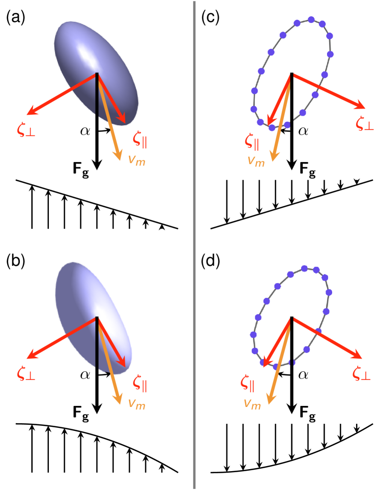
The major axis of a tank-treading capsule (ring) includes with the straight flow lines of both flows an angle, whereby the sign and the magnitude of this angle are determined by the sign and the magnitude of the local shear rate [44]. The buoyancy force acting on a particle points upward for a light and downward for a heavy particle, i. e. it is either parallel or antiparallel to the flow lines. According to different drag coefficients, , an external force on an inclined capsule (ring) in shear flow causes an oblique migration velocity , as shown in Fig. 2. The inclination angle of the ellipsoid (ring) and therefore the inclination angle of depend on the sign of the local shear rate (see also analytical results below). For both flows a reversal of the flow direction leads to a reversal of the local shear gradient and simultaneously to a reversal of the horizontal component ( component) of the migration velocity : I. e. a reversal of the flow direction causes a reversal of the cross-streamline migration of non-neutrally buoyant soft particles. Furthermore, if the buoyancy force is downward (upward) then the shear gradient and the horizontal migration direction are antiparallel (parallel).
4 Small capsule-deformations
The shape of a Neo-Hookean capsule, its anisotropic drag and its cross-streamline drift in a linear shear flow can be determined analytically in the range of a small capillary number [43, 44]. In this limit, the capsule shape is given by the equation
| (14) |
which describes an ellipsoid with three different axes. The major axis forms with the undisturbed straight stream lines an angle of about . The length of the three axes are
| (15) |
In order to proceed with analytical calculations we make a common approximation and assume rotational symmetry with respect to the major axis. Then the length of the major/minor axis are given by
| (16) | ||||
| (17) |
The drag coefficients of a rotational symmetric ellipsoid parallel and perpendicular to the major axis are given by Perrin’s formulas (see e.g. [46] and references therein)
| (18) | ||||
| (19) |
with . The migration velocity of the ellipsoid perpendicular and parallel to the stream lines is obtained by decomposing the buoyancy fore into its component along the major axis, , and perpendicular to it, . The migration velocity across the streamlines is then given by
| (20) |
A Taylor expansion with respect to Ca gives at leading order
| (21) |
The capsule’s shape in a Poiseuille flow at an off-center position has the shape of a slightly deformed ellipsoid, as indicated also in Fig. 2. The deformation of a spherical shape is determined by the local shear rate in Poiseuille flow at the capsule’s center : . With the local capillary number one obtains within this approximation the position dependent cross-streamline migration velocity in Poiseuille flow
| (22) |
The force induced velocity relative to the unperturbed flow can be calculated analogous as in a linear shear, which includes besides result from the Stokes drag a deformation dependent correction proportional to :
| (23) |
Its explicit form for Poiseuille flow is then
| (24) |
If the external force is antiparallel to the flow and if it is large enough, the capsule moves against the flow direction. This is approximately the case if is larger then the velocity of the Poiseuille flow at the capsule center
| (25) | ||||
| (26) | ||||
| (27) |
5 Numerical results on CSM in unbounded flows
To verify our approximate analytical predictions and qualitative descriptions of the migration of non-neutrally buoyant soft particles in unbounded flows, we simulate the Stokesian dynamics of capsules and a rings.
This ensures that the occurred migration is no inertial effect or imposed by wall interactions. Since the migration reversal does only depend on the local shear rate, we confine the numerical investigation, without loss of generality, to that of the Poiseuille flow.
The setup for all simulations can be seen in Fig. 1. The imposed flow is a Poiseuille flow applied in y-direction with . The deformable particles are placed with center of mass positions . As consequence, particles with negative migration velocity () will migration to the wall and positive migration means center migration.
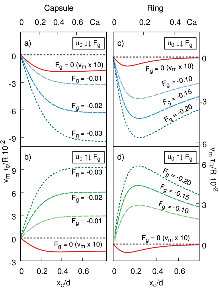
As reference, we first discuss the case without external force, which is shown as red curve in Fig. 3. For this case we observe the already known center migration for both, the capsule and the ring [zitat: zentrumsmigration für soft-particle low Re].
If we now apply a gravitational force parallel to the stream lines (), we see an increase of the center migration (Fig. 3 (a) and (c)). This additional center-migration is enlarged for higher external forces. During the migration to the center, the migration speed decreases, which is a result of the position dependent shear-rate of the Poiseuille flow. When the particles reach the center line, vanishes and the particle follows the stream lines.
For the case of antiparallel force and flow-direction (), we find the opposite behavior (Fig. 3 (b) and (d)). The migration direction is reversed and the particles experience a positive migration-velocity. This effect is also correlated to the force strength and position of the particle. The migration in this case does not vanish on its way remote from the center, since there is no repulsive interaction with the walls. This migration reversal is observed for both, the capsule and the ring. Both migration curves look similar, which means the reversal effect does not depend on the detail of the particle but is a more generic feature of the interplay between deformation and external forces. This is consistent with the results from [37], where they could measure this behavior for bundled DNA-molecules, which have no impenetrable surface.
6 Cross-stream drift between walls
6.1 Migration of a sedimenting capsule
The influence of the flat walls of the channel should also be studied. At first we investigate the interaction between a sedimenting capsule and the walls of the channel without a flow. We observe a repulsion of the capsule from the wall which depends on the stiffness of the capsule, see Fig. 4. The softer the capsule is the stronger is the repulsion. This is consistent with the fact that a solid particle sinks parallel to the wall (see zitat).
The reason of the repulsion is the deformability of the capsule. The part of the capsule closer to the wall is subjected to a friction with the wall (transmitted via the fluid) and lags behind. The other part of the capsule more away from the wall moves therefore faster. This stretches the capsule and lasts until a steady state is reached which has a shorter and a longer axis. The longer axis points away from the wall if seen from the center of the capsule in direction of the external force. This leads, as described above, to an asymmetric drag and the capsule moves not completely in direction of the force but a bit shifted towards the major axis. This means it drifts away from the wall. This mechanism is different from the wall repulsion of capsules in a shear flow without a external force where a lift force due to the tank treading leads to the wall repulsion.
6.2 Dynamics of rings and capsules in Poiseuille flows
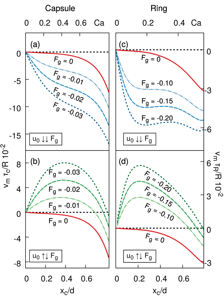
The contribution of the wall interaction to the migration of capsules in a Poiseuille flow is examined here. The Fig. 3 and 5 show the migration velocity of a ring and a capsule as function of the capillary number Ca for different values of the force in case of an unbounded or an bounded flow. A comparison of both Fig. shows that far away from the walls the migration is similar in case with and without walls but is changed close to the walls where the repelling lift force becomes important. In case of a parallel external force and flow the lift force enhances the migration to the center. In case of an antiparallel external force and flow the bulk migration to the wall is hindered or surpassed by the lift force. The capsule and the ring migrates away from the wall if it is close to it. This leads to stable lateral position outside the channel center where the migration due to the external force and due to the the lift force are equal.
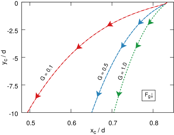
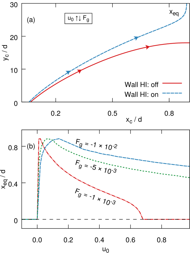
The drift towards such a stable wall distance at and the dependence of on and is shown in Fig. 6 . If the flow is parallel to the force the stable position is the channel center because the external force, the center migration occurring also without an external force and the wall repulsion lead to a migration to the center. If the flow is reversed (meaning now antiparallel to the force) the migration due to the force leads to a wall migration and stable, lateral off-center positions occur. They are at approximately the closest to the wall depending on the external force. Beyond this maximal off-center position becomes closer to the center the higher is because the increasing tank-treading motion and is the closer to the wall the larger the external force is. With a weak force and a strong flow e.g. and the stable position is again the center of the channel despite they are antiparallel.
6.3 Comparison of simulation methods and analytical approximation
We used in our simulations with the Oseen and Blake tensor the assumption that the external force acts on the surface of the capsule. In our analytical approximation we approximate the shape of the capsule as an rotational ellipsoid to calculate the drag. To justify these approximations we compare the results with an Lattice Boltzmann method (LBM) with the BGK collision operator and a singe relaxation time. Flow and particle are coupled by the immersed boundary method. With lattice Boltzmann, it is possible to simulate an external force that acts on the interior of the capsule or on the surface.
With the LBM we can compare the analytical approximation, the Oseen and Blake tensor simulation, a LBM simulation with an external force acting on the surface and a second LBM simulation with an external force acting on the interior of the capsule. We determine the migration velocity of a capsule with an external force in an antiparallel directed, bounded Poiseuille flow as function of the lateral position, see Fig. LABEL:yc_vm_LBM.eps. All simulations show that the capsule migrates towards the walls and stops at a certain distance to the wall due to the wall repulsion. Furthermore they all display zero migration in the center, a maximum of the migration in the middle between center and wall and a stable, stationary position at approximately . So the simulations agree qualitatively. Quantitatively the simulations differ at the maximum of the migration velocity (approximately a factor of two) but agree well at low capillary numbers close to the center of the channel. This means the Oseen and Blake tensor describes the capsule qualitatively correct.
The analytical approximation agrees well at low capillary numbers at the center of the channel. This is due to the fact that small deformations are assumed. Also the analytical approximation can not reproduce the stationary position because the wall repulsion is not included here. This means the analytical approximations is justified as long as the assumptions of a small capillary number and a position far away from the wall are given.
7 Summary and conclusions
The migration of the sinking (elevating) soft particles away from the walls has a similar origin as the lift force observed
in linear shear flow [21, 22, 23].
Migration during sedimentation
This cross-streamline migration is more efficient than bulk migration.
By this method we can separate particles with respect to their density and stiffness.
Shear flow
Acknowledgements.
References
- [1] \NameSquires T. M. Quake S. R. \REVIEWRev. Mod. Phys.772005978.
- [2] \NameKirby B. J. \BookMicro- and Nanoscale Fluid Mechanics (Cambridge Univ. Press, Cambridge) 2010.
- [3] \NameNguyen N.-T. Wereley S. T. \BookFundamentals and Applications of Microfluidics (Artech House, Boston) 2010.
- [4] \NameWhitesides G. M. \REVIEWNature4422006368.
- [5] \NamePopel A. S. Johnson P. C. \REVIEWAnnu. Rev. Fluid Mech.37200543.
- [6] \NameGraham M. D. \REVIEWAnn. Rev. Fluid Mech.432011273.
- [7] \NameSackmann E. K., Fulton A. L. Beebe D. L. \REVIEWNature5072014181.
- [8] \NameDahl J. B., Lin J.-M. G., Muller S. J. Kumar S. \REVIEWAnn. Rev. Chem. Biomol. Eng.62015293.
- [9] \NameAmini H., Lee W. Carlo D. D. \REVIEWLap Chip1420142739.
- [10] \NameGeislinger T. M. Franke T. \REVIEWAdv. Coll. Int. Sci.208201414.
- [11] \NameSajeesh P. Sen A. K. \REVIEWMicrofluid Nanofluid1720141.
- [12] \NameMisbah C. \REVIEWJ. Fluid Mech.76020141.
- [13] \NameFarutin A., Piasecki T., Slowicka A. M., Misbah C., Wajnryb E. Ekiel-Jeźewska M. L. \REVIEWSoft Matter1220167307.
- [14] \NameSegré G. Silberberg A. \REVIEWNature1891961209.
- [15] \NameShafer R. H. \REVIEWBiophy. Chem.21974185.
- [16] \NameNitsche L. C. \REVIEWAIChE J.421996613.
- [17] \NameGhigliotti G., Rahimian A., Biros G. Misbah C. \REVIEWPhys. Rev. Lett.1062011028101.
- [18] \NameSekhon G., Armstrong R. Jhon M. S. \REVIEWJ. Polymer Sci.:Polymer Phys.201982947.
- [19] \NameBrunn P. O. \REVIEWInt. J. Multiphase Flow1871983202.
- [20] \NameJhon M. S. Freed K. F. \REVIEWJ. Polymer Sci.: Polymer Phys.231985255.
- [21] \NameCantat I. Misbah C. \REVIEWPhys. Rev. Lett.831999880.
- [22] \NameSeifert U. \REVIEWPhys. Rev. Lett.831999876.
- [23] \NameAbkarian M., Lartigue C. Viallat A. \REVIEWPhys. Rev. Lett.882002068102.
- [24] \NameMa H. Graham M. D. \REVIEWPhys. Fluids172005083103.
- [25] \NameLeal L. G. \REVIEWAnn. Rev. Fluid Mech.121980435.
- [26] \NameMandal S., Bandopadhyay A. Chakraborty S. \REVIEWPhys. Rev. E922015023002.
- [27] \NameKaoui B., Ristow G. H., Cantat I., Misbah C. Zimmermann W. \REVIEWPhys. Rev. E772008021903.
- [28] \NameCoupier G., Kaoui B., Podgorski T. Misbah C. \REVIEWPhys. Fluids202008111702.
- [29] \NameDoddi S. K. Bagchi P. \REVIEWInt. J. Multiphas. Flow342008966.
- [30] \NameFarutin A. Misbah C. \REVIEWPhys. Rev. E892011042709.
- [31] \NameWatari N. Larson R. G. \REVIEWPhys. Rev. Lett.1022009246001.
- [32] \NameLaumann M., Bauknecht P., Gekle S., Kienle D. Zimmermann W. \REVIEWEPL117201744001.
- [33] \NameJo I., Huang Y., Zimmermann W. Kanso E. \REVIEWPhys. Rev. E942016063116.
- [34] \NameJeffrey R. C. Pearson J. R. A. \REVIEWJ. Fluid Mech.221965721.
- [35] \NameKim Y. W. Yoo J. Y. \REVIEWLap Chip920091043.
- [36] \NameProhm C. Stark H. \REVIEWLap Chip1420152115.
- [37] \NameZheng J. Yeung E. S. \REVIEWAnal. Chem.7420024536.
- [38] \NameUsta O. B., Butler J. E. Ladd A. J. C. \REVIEWPhys. Rev. Lett.982007098301.
- [39] \NameFeng J., Hu H. H. Joseph D. D. \REVIEWJ. Fluid Mech.261199495.
- [40] \NameBlake J. R. \REVIEWProc. Camb. Philos. Soc.701971303.
- [41] \NameDhont J. K. G. \BookAn Introduction to dynamics of colloids (Elsevier, Amsterdam) 1996.
- [42] \NameJones R. B. \REVIEWJ. Chem. Phys.1212004483.
- [43] \NameBarthès-Biesel D. \REVIEWJ. Fluid Mech.1131981251.
- [44] \NameBarthès-Biesel D. \REVIEWAnnu. Rev. Fluid Mech.48201625.
- [45] \NameKrüger T., Kusumaatmaja H., Kuzmin A., Shardt O., Silva G. Viggen E. M. \BookThe Lattice Boltzmann Method - Principles and Practice (Springer, Berlin) 2016.
- [46] \NameHappel J. Brenner H. \BookLow Reynolds Number Hydrodynamics (Prentice-Hall, Englewood Cliffs) 1981.
- [47] \NameKrüger T., Kaoui B. Harting J. \REVIEWJ. Fluid Mech.7512014725.