Laminar free shear layer modification using localized periodic heating
Abstract
The application of local periodic heating for controlling a spatially developing shear layer downstream of a finite-thickness splitter plate is examined by numerically solving the two-dimensional Navier-Stokes equations. At the trailing edge of the plate, oscillatory heat flux boundary condition is prescribed as the thermal forcing input to the shear layer. The thermal forcing introduces low level of oscillatory surface vorticity flux and baroclinic vorticity at the actuation frequency in the vicinity of the trailing edge. The produced vortical perturbations can independently excite the fundamental instability that accounts for shear layer roll-up as well as the subharmonic instability that encourages the vortex pairing process farther downstream. We demonstrate that the nonlinear dynamics of a spatially developing shear layer can be modified by local oscillatory heat flux as a control input. We believe that this study provides a basic foundation for flow control using thermal-energy-deposition-based actuators such as thermophones and plasma actuators.
keywords:
shear layer, flow control, instability.1 Introduction
Shear layer may be the most common flow that arises in virtually every applications, including jets, flow over a cavity, separated boundary layer over an aerodynamic body, and merging of two streams behind the trailing edge of an airfoil. Accordingly, active control of shear layer flows has been a major area of interest for the community. Early efforts on control of shear layers arising from separated flows have been summarized by Gad-el Hak & Bushnell (1991). For jet flows, Wiltse & Glezer (1998) examined the use of dissipative-range forcing with piezoelectric actuators and found that the high-frequency actuation is able to enhance the turbulent energy cascade and increase the dissipation of turbulent kinetic energy. Later, Seifert & Pack (1999) examined the effect of synthetic jet actuation for flow control of a separated flow over a NACA 0015 airfoil and found that the actuation is able to delay stall and improve post-stall aerodynamic performance. With plasma actuators, these control effects are also observed by Post & Corke (2004) on the same airfoil. The uses of plasma actuators on other shear layer setups have been continuing to attract research interests (Samimy et al., 2007; Corke et al., 2009; Akins et al., 2015). Synthetic-jet-based flow control of a shear layer that forms in a separated flow over a wall-mounted hump is studied by Greenblatt et al. (2006), who showed control input from the jet is able to change the generation rate of turbulent kinetic energy along the shear layer. For shear layers in cavity flows, Cattafesta et al. (2008) summarized flow control attempts using a number of modern actuators. Flow over a backward-facing step is also a canonical problem setup where a shear layer is formed, and was chosen by Vukasinovic et al. (2010) to investigate high-frequency actuation effects from a spanwise arrangement of synthetic jets. While the above studies do not encompass all studies to date, they show the breadth of active control techniques being applied to shear layers that arise from a range of flows.
Amongst the aforementioned flows, the free shear layer formed by the mixing of two streams with different velocities is considered especially to be the canonical configuration for shear layer flows. Studies on the characteristics of free shear layer dates back to the seminal work of Brown & Roshko (1974), where they showed that the large spanwise roll-up coherent structures forming behind the trailing edge of a splitter plate serve as the main driving force for mixing of two streams and induce the entrainment that feeds fluid from two streams to the mixing region. Along with their work, Winant & Browand (1974) and Ho & Huang (1982) have attributed the initial shear layer roll-up to the fundamental instability waves, where as their subharmonic instability accounts for the vortex merging downstream. These findings are extended to compressible flow later by Elliott & Samimy (1990) and Clemens & Mungal (1995).
As fundamental studies on the free shear layer instabilities, Ho & Huang (1982) introduced (non-local) subharmonic velocity disturbances in the entire free streams. Bechert & Stahl (1988) found the external acoustic excitation is also able to trigger the instability wave in the shear layer. While leveraging flow instabilities is a general strategy for flow control, introducing control inputs in a limited local region may be a more practical approach than introducing control inputs externally. On the other hand, Barone & Lele (2005) studied the receptivity of the shear layer behind a finite-thickness splitter plate to various type of disturbances by performing adjoint simulations. Temperature disturbance is among one of them and the shear layer is found to be receptive to such perturbation. However, studies on the excitation of shear layer instability by directly manipulating the local temperature are limited in the literature. Based on these two reasons, the use of a localized thermal forcing input for flow control on a free shear layer draws our interests to the present study.
The objective of this study is to assess the effectiveness of the use of local periodic heating for modifying the early evolution of a free shear layer. Two-dimensional Navier–Stokes equations are numerically solved to simulate a spatially developing shear layer downstream a finite-thickness splitter plate, with local periodic heating introduced at the trailing edge. As it has been pointed out by Crighton (1985) and Bechert (1988), active control of shear layer by introducing control inputs downstream of the trailing edge appears ineffective, but control via manipulation of the instabilities at the onset of a shear layer can be effective. A slight perturbation during the genesis of a shear layer can lead to the overall change in flow physics downstream, because its instability characteristics determine which existing disturbances can be amplified. Nonlinear effect takes place when disturbance becomes large in magnitude and transfers energy among modes while creating new ones, which drives the evolution of the flow. Thus, focusing forcing input to the origin of a shear layer is favorable for flow control since the input can leverage the flow instabilities to grow and alter the flow behavior downstream.
Our fundamental study on the use of local periodic heating as a forcing input to modify the spatial evolution of a shear layer is inspired by the development in thermophones and nanosecond pulse driven dielectric barrier discharge (ns-DBD) actuators. For the former, thermophone is a sound generation technique discovered by Arnold & Crandall (1917). With the application of alternating current (AC) over a platinum film, they found that the Joule heating on the film periodically increases the surrounding fluid temperature and leads to local pressure fluctuations at the frequency of alternating current. This thermophone technique was not widely utilized in the past due to the relatively large power required for a desired surface pressure disturbance level. In recent years, however, this drawback has been overcome by the use of graphene- and carbon-nanotube-based membranes for thermophones. Compared to traditional metal membranes, the carbon-based membranes can be fabricated extremely thin, usually around mm (Tian et al., 2011), such that its heat capacity per unit area (HCPUA) is at least two orders of magnitude lower than that of the metal films. Since the output power of pressure disturbance delivered to the surrounding flow field is inversely proportional to the material HCPUA, the use of carbon-based membranes dramatically enhances the device efficiency. The operating frequency is also extended in range ( to kHz) with these membranes (Tian et al., 2011; Bin et al., 2015). Considering thermophone as a new candidate for flow control actuators, the broadened range of its operating frequency is able to encompass that of many flow control applications.
On the other hand, the use of ns-DBD actuators for flow control has also become widespread in recent years (Little et al., 2012; Lehmann et al., 2014). The control mechanism of ns-DBD plasma actuation is believed to primarily rely on the deposition of thermal energy (Nudnova et al., 2010; Adamovich et al., 2012), in contrary to alternating current driven dielectric barrier discharge (ac-DBD) actuators that employ electrohydrodynamic effect to introduce momentum perturbation (Abe et al., 2008; Corke et al., 2010). Numerous studies have reported the rapid heating effect near the pulse-driven plasma actuator and attributed the kinetic mechanism of the localized heating to the energy transfer to molecular translational/rotational modes on a sub-microsecond time scale (Aleksandrov et al., 2010; Popov, 2011). For both thermophone and ns-DBD actuators, their energy-flux-based actuators rely on no mechanical moving parts. Moreover, their sheet-like arrangement facilitates surface-compliant installation without occupying any internal space or adding significant weight. This advantage in installation allows them to be mounted on virtually any surface, and extend their potential uses for flow control on applications including rotorcraft blades and small-scale unmanned air vehicle wings.
In this study, we numerically examine the capability of this thermal energy-flux-based actuation for flow control on a canonical free shear layer flow. In what follows, we describe the problem and discuss the computational setup in section 2. Two boundary conditions for modeling local periodic heating are presented in section 2.3. Two-dimensional baseline shear layers are characterized in section 3. In section 4, the underlying mechanism of how thermal actuation can introduce perturbations to the flow field and alter the characteristics of the downstream shear layer is revealed by examining the near-field effect of the actuator. The flow control effect by local periodic heating on the downstream shear layer is discussed in detail in section 5. We conclude this study in section 6 by offering summarizing remarks.
2 Computational setup
2.1 Problem description
We consider a two-dimensional free shear layer as a model problem to examine the effectiveness of thermal actuation. Two incoming streams, initially separated by the splitter plate, at Mach numbers (top) and (bottom) with the same free stream acoustic speed, , and pressure, , form a spatially developing shear layer from the trailing edge, as illustrated in figure 1. Following the definition by Papamoschou & Roshko (1988), the mean convective Mach number for the shear layer is , with the density ratio being unity (). The plate-thickness-based Reynolds number, , is set to , where is the convection velocity, is the plate thickness and is the free-stream dynamic viscosity. The boundary layers on both sides of the plate are prescribed with the same momentum thickness, , which is chosen to be , and of the splitter plate thickness, , resulting in the momentum-thickness-based Reynolds number to range from to .
2.2 Computational approach
The governing equations for the free shear layer are the compressible Navier–Stokes equations:
| (1) | ||||
| (2) | ||||
| (3) |
with the equation of state for ideal gas:
| (4) |
where is the specific heat ratio. The non-dimensional variables in equations 1 to 4 are the spatial coordinate , time , density , velocity , pressure , energy and temperature according to the non-dimensionalization of
We note that the shear layer roll-up wavelength, , may also be used for the non-dimensionalization of the spatial coordinate in order to provide fair comparisons between different . In this paper, it will be clearly stated which length scale is being used for non-dimensionalization. The dimensionless parameters appearing in the governing equations are the acoustic Reynolds number and Prandtl number, given by
where is the free stream thermal diffusivity.
To simulate the flow, we consider the two-dimensional set of equations and use the compressible flow solver CharLES (Khalighi et al., 2011a, b; Brès et al., 2017), which utilizes a second-order-accurate finite-volume method and a third-order Runge–Kutta scheme for time stepping. We use , and in the present study. Both values are representative of standard air. The temperature-varying dynamic viscosity, , is evaluated by the power law as (see Garnier et al., 2009). The power law models the dynamic viscosity variation well for standard air in the range of . This range is suitable for the current study with local thermal inputs, where we observe the temperature fluctuation is within about .
The computational domain, as illustrated in figure 1 (left), has a streamwise extent of and a maximum vertical extent of , similar to the domain setup used by Sharma et al. (2011). The splitter plate has an elliptic trailing edge with eccentricity of , with its tip positioned at the origin, . The domain is discretized with a structured body-fitted mesh around the splitter plate. The near-wall resolution is (see Choi & Moin, 2012), where is the wall shear velocity and is the wall shear stress. To resolve the interaction between the shear layer and the localized periodic heat forcing, the wall-normal grid stretching rate is limited such that the only reaches a maximum of within from the wall. The overall grid size is approximately . The DNS results from this mesh were verified by comparing the flow field to that from a finer mesh, where the grid is refined in the sheared region and has the size of grid points. No noticeable differences are found in the results from these two meshes.
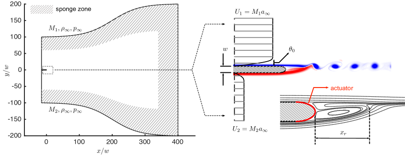
Two streams are introduced to the computational domain from the inlet boundary (left) using Blasius boundary layer velocity profile. Their density profiles are computed using the Crocco–Busemann relation, with the same far-field temperature and pressure. Sponge zone is applied along the top, bottom and outlet (right) boundaries to damp out existing acoustic waves and vortical structures (Freund, 1997). The target state of the sponge zone at the top and bottom boundaries are set to and , respectively. At the outlet, the time-average flow is set to be the target state of the sponge zone.
In this study, the effects of momentum thickness, the forcing frequency, and amplitude are examined in the context of modifying the characteristics of the shear layer. The flow control setup using local periodic heating and the associated input parameters are discussed below.
2.3 Local periodic heating
The thermal actuator model is implemented in the numerical simulations through a boundary condition. Over the elliptic trailing edge of the splitter plate, an oscillatory energy-flux (unsteady Neumann) boundary condition that introduces local periodic heating is prescribed to the energy equation 3, along with no-slip boundary condition for the momentum equation 2. In the present study, we consider two forms of periodic heating. First, we consider a temporally oscillatory heat flux with zero mean as:
| (5) |
where the net heating input to the local fluid is zero over the forcing period. We also consider another forcing input which introduces a positive direct current (DC) offset to the expression of in equation (5) such that the heat flux is always positive over the duty cycle:
| (6) |
In the expressions for and , and denote the forcing frequency and amplitude, respectively. For each choice of , the forcing frequency, , is normalized by the corresponding baseline shear layer roll-up frequency, , and is varied from and , over which we observe forcing effects. Since the heat flux amplitude, , accounts for the forcing power that is introduced to the shear layer flow, we normalize the total heating power from the trailing edge by the characteristic kinetic energy flux across the momentum thickness as
| (7) |
where
| (8) |
is the cyclic average heating power introduced by the actuator. This normalization can account for the use of higher forcing amplitude, , for thicker initial momentum thickness, , for a fair comparison of forcing requirements across different , since thicker shear layer is expected to necessitate higher level of perturbation inputs to modify the shear layer. We parameterize the normalized forcing power in this study in the range of to . This value is of the same order of magnitude of those used in plasma-based flow control works (Samimy et al., 2007; Corke et al., 2010; Sinha et al., 2012; Akins et al., 2015). We also note that the maximum temperature fluctuation observed over the surface of the actuator is within about the free stream temperature with the use of the largest forcing amplitude, , in cases.
3 Baseline characterization
3.1 Shear layer characteristics
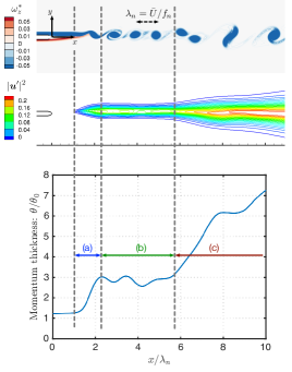
Let us first characterize the baseline flows at three momentum thicknesses specified at the inlet: namely, , and . We focus our interest in the region within the streamwise extent of , where is the fundamental shear layer roll-up wavelength. Shown in figure 2 are a snapshot of the normalized instantaneous spanwise vorticity (top), the velocity fluctuation magnitude (middle), and the momentum thickness profile (bottom) for the baseline flow with . In this work, the momentum thickness is computed using the density and streamwise velocity profiles in the shear layer as
| (9) |
where the over-bar denotes the time-averaged quantity based on the flow statistics collected over more than 200 roll-up periods. Comparing the spatial growth of momentum thickness to the instantaneous flow field, we classify the shear layer flow into three regions: (a) the shear layer roll-up region, where the momentum thickness exhibits the first rapid growth behind the trailing edge; (b) the isolated vortex region, where each formed vortex remains compact as an individual and convects closely along the centerline; (c) the vortex merging region, where the vortices start to deviate from the centerline while convecting downstream, as the initiation of the vortex merging process. This last region can be identified by the second rapid growth of the momentum thickness. These three regions can be also characterized by the streamwise change in velocity fluctuation magnitude. In regions (a) and (c), the spatial extent and the magnitude of fluctuation are both increasing, but region (b) shows no apparent changes in the growth of the momentum thickness except for the rippling variation in the momentum thickness profile. The cause of this ripple due to the orientation of the vortex evolving as the vortex convects downstream, which is discussed in appendix A. Later in Section 5, the forcing effect of periodic heating on the characteristics of theses three regions are examined in further detail.
3.2 Influence of the splitter plate thickness
Due to the finite thickness of the splitter plate, a small recirculation region of length develops directly behind the blunt trailing edge of the splitter plate, as illustrated by the time-average streamlines in figure 1 (bottom-right). This streamline pattern for two boundary layers merging behind the trailing edge of a finite-thickness splitter plate is also observed by Sharma et al. (2011) and Laizet et al. (2010). The recirculation region can be viewed as a wake behind the finite-thickness splitter plate and result in a deficit in the profile streamwise velocity. In the theoretical study by Zhuang & Dimotakis (1995), they reported that a wake instability mode can be introduced to the shear layer which has a deficit in its streamwise velocity profile due to a wake component, and the growth rates of both the wake mode and the fundamental shear layer mode increase when the streamwise velocity profile has a greater wake deficit. Mehta (1991) experimentally showed that the splitter plate wake plays a dominant role in the development of the shear layer. The wake increases the turbulence levels in the near-field and shortens the development distance to achieve self-similarity in shear layer profiles. Remarks by Mehta (1991) on the lack of simple scaling for the shear layer with the presence of the wake also suggest that nonlinear interaction is taking place between the wake and the shear layer. Laizet et al. (2010) performed DNS of shear layers developing behind three different trailing edge geometries and reported that the presence of the wake can lead to different turbulent structures and shear layer spreading rate. We note, however, that there is no trace of von Kármán shedding observed in the simulations considered here, in spite of the presence of the recirculation region.
 |
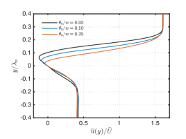
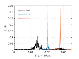 |
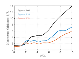
The lengths of the recirculation regions for each baseline cases with varied momentum thickness are summarized in Table 1, where the change in the wake length, , is limited to while is increased by five times. At the streamwise station of , the time-average streamwise velocity profile over the normalized transverse coordinate is presented in figure 3. Note that the normalization of causes the velocity minimum to appear at different location for different choice of , since the value of influenced by the value of . In figure 3, we observe that the wake deficit increases in both its transverse extent and maximum velocity deficit for thinner incoming boundary layer. In figure 4 we show the momentum thickness profile over the streamwise coordinate normalized by the corresponding roll-up wavelength for each case. As discussed previously using for the baseline characterization, the three-region growth patterns are also observed in the other two baseline cases. The initiation of merging takes place at for all cases. However, thicker for the isolated vortex region and delayed roll-up are observed for thinner . These observations can be attributed to the stronger effect of wake when is thinner. The effect of the plate wake can be also seen in the shear layer roll-up Strouhal number, , in Table 1. We also note that the values of are lower than the prediction from linear instability theory (Monkewitz & Huerre, 1982; Ho & Huerre, 1984), , in all baseline cases. This also suggests that the effective initial momentum thickness is thicker than that on the high speed side, , because of the presence of the wake. Therefore, for thinner where the wake effect is more pronounced, the greater deviation of from is observed. The stronger wake effect on thin can also be inferred from figure 4, where the transverse velocity spectra at for three baseline cases are shown. The clean peaks in the cases of and suggest a synchronized shear layer roll-up and shedding, whereas the cause of the less prominent peak and broader frequency content in the case of can be attributed to the nonlinear interaction between the shear layer roll-up mode and the wake mode that redistribute the energy of the roll-up frequency to other nearby frequencies.
3.3 Local stability analysis
To determine regions with linear growth of perturbation and predict the corresponding growth rate for the Kelvin–Helmholtz instability, local linear spatial stability analysis on the baseline flow is also performed at the onset region and the isolated vortex region of the shear layer. We compute the corresponding spatial growth rate at a specified perturbation frequency using the time-average density and streamwise velocity profiles as the base flow for the compressible Rayleigh equation (Sabatini & Bailly, 2014).
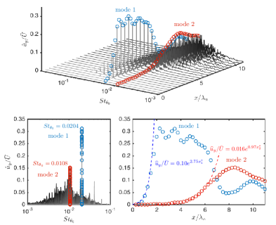
Figure 5 shows the stability analysis results for baseline flow. Time-average flow profiles at two streamwise stations (shown on the left) are chosen about which to perform the instability analysis. The first station , corresponding to or , is located slightly downstream of the recirculation region but upstream of the shear layer roll-up region. In figure 2, the station is located in the flat region before the first sudden growth of the momentum thickness. Similarly, we choose the second station , where or , in the isolated vortex region indicated by the second flat region and before the second sudden growth. In figure 5, the most amplified frequencies and the corresponding spatial growth rates are and for stations and , respectively. We compare these values to the results from DNS shown in figure 6. In the top sub-figure, the spectra of transverse velocity is plotted over a series of streamwise locations. The symbol (referred to as mode 1 hereafter) represents the first spatially amplified mode and (referred to as mode 2 hereafter) depicts the second mode. Their corresponding frequencies in terms of Strouhal numbers are and for modes 1 and 2, respectively, as captured in the bottom-left figure. Compared to the frequencies predicted by linear stability theory, the differences are only approximately and for the modes 1 and 2, respectively. The spatial growth of the modal amplitude can be seen in bottom-right subplot of figure 6. Also, in the bottom-right figure, the amplitude growth of the modes 1 and 2 are fitted with exponential growth function in and , respectively for each mode. We also find the growth rates from the fitting differ only by and from the prediction of the linear theory for roll-up and merging modes, respectively. The fitted function deviates from the simulation data and past and , respectively. These deviations are expected since, referring to figure 2, these two stations have already reached the vortex formation and merging regions where momentum thickness exhibits a sudden streamwise growth and the parallel flow assumption is no longer valid.
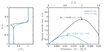
The agreement between the results from DNS and the linear stability analysis on the baseline flow provides deep insight into the growth of perturbations in the aforementioned regions. As we discuss later, the frequencies in the vicinity of that of mode 2 are also considered as candidates for the actuation frequency of the local periodic forcing in Section 5. The growth rate prediction at the forcing frequency will also be compared to the forced cases later in discussions related to figures 10 and 14.
4 Thermal control mechanism
In this section, the local effects of periodic thermal forcing is studied to understand how the thermal perturbations give rise to hydrodynamic perturbations and modifies the shear layer physics downstream. The local temperature fluctuation and surface pressure disturbance introduced by local periodic heating change local vorticity flux through the solid boundary, either by changing the surrounding fluid properties or wall-tangential pressure gradient (Hornung, 1989; Wu & Wu, 1993). The fluctuations in pressure and density in the vicinity of the actuator may also generate volumetric baroclinic vorticity, . In this two-dimensional study, we evaluate the local wall-normal vorticity flux using (Wu & Wu, 1993)
| (10) |
where and are the dynamic viscosity and spanwise vorticity, respectively, subscript denotes the wall adjacent quantities, is the spatial parameter describing the splitter plate surface, and is the unit wall-normal vector. In two-dimensional Cartesian coordinates, the baroclinic torque generation is computed using
| (11) |
These two quantities from the baseline and forced flows are examined below.
Without loss of generality, we consider the case with . The two quantities in equations 10 and 11 for the baseline and forced flows are examined to quantify their fluctuation magnitudes and frequencies. The forced and baseline computations are started at from the same initial condition, which is associated with the instantaneous baseline flow with steady flow statistics. For the forced case, periodic heating at the trailing edge is turned on at using equation 5 with and amplitude of . Flow statistics are collected over .
| \begin{overpic}[scale={0.535}]{Figures/fig08a} \end{overpic} | \begin{overpic}[scale={0.535}]{Figures/fig08b} \end{overpic} |
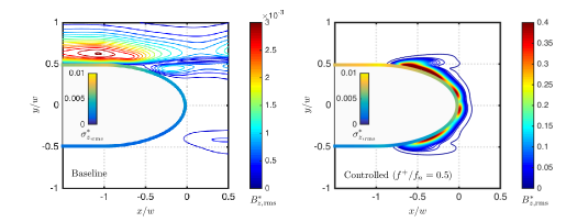
The change in these two quantities between the forced and baseline cases is shown in figure 7, where is the root-mean-square value of , normalized by , namely, the total Euler flux of vorticity introduced by two inlet boundary layers. Similar normalization is used for . We observe that both of these quantities exhibit higher fluctuation magnitudes in the thermally forced flow. Furthermore, note that the maximum magnitude of in the vicinity of the actuator is compared to the baseline flow. As reported by Cheung & Lele (2009), the baroclinic vorticity generation plays an important role in governing shear layer dynamics, especially for subsonic shear layers. In their study, the order of magnitude difference between a heated (free-stream temperature ratio of ) and an unheated (with the same free-stream temperature) shear layer is also of . The additional generation of baroclinic vorticity takes part in the vortex dynamics in the heated shear layer and leads to different behaviors from the unheated shear layer.
We compute the total vorticity flux over the trailing edge as
| (12) |
and the total baroclinic generation near the trailing edge as
| (13) |
The quantities and are normalized by and plotted in figure 8 over time and frequency domains. As observed from the frequency domain, both of these quantities peak at the forcing frequencies, suggesting the fluctuations in and are indeed induced by the local periodic forcing.
The present flow control technique utilizes local periodic heating as an energy-deposition-based forcing, which introduces additional generation of vorticity. As vorticity quantifies the rotation of fluid particles, we may also consider the present technique as a vorticity-based forcing, in contrast to other momentum-based flow control techniques such as synthetic jets (Glezer & Amitay, 2002). When the extra oscillatory vorticity is introduced to the shear layer at its onset, it can trigger the instability responsible for the shear layer roll-up, or modify the strength of each vortex formed from shear layer roll-up and change their interaction dynamics downstream.
5 Flow control effects on the shear layer
In this section, the influence of the forcing frequency () and the forcing type ( and ) on the shear layer is examined. Each DNS is initialized with an instantaneous flow field from the baseline flow, with steady statistics based on at least fundamental roll-up periods. Forcing is turned on from this initial condition. Flow statistics for the controlled flows are collected after roll-up periods. The reported controlled flow spectrum and mean-flow-based momentum thickness are evaluated over at least another roll-up periods. We start the discussion with the use of in section 5.1 and 5.2. Forcing with , which is with a positive direct current (DC) offset, is examined in section 5.3.
5.1 Spreading enhancement ()
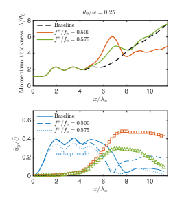
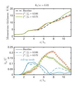
We examine the forcing effect when the actuation frequency is close to the first subharmonic of the roll-up frequency with the use of . Two forcing frequencies are examined: namely, and . The forcing frequency is selected for being close to the frequency of mode 2 found in figure 6. The exact first subharmonic is also chosen. For fair comparison, all cases presented in this section are based on the same forcing power of . In the discussions below, we first highlight the common forcing effects for these two forcing frequencies. We then discuss the differences between the two forced cases.
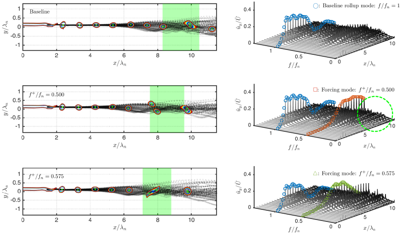
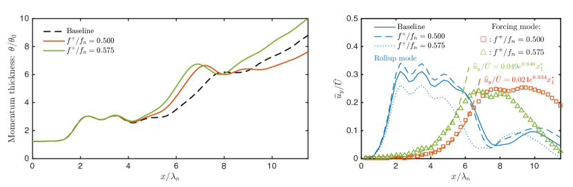
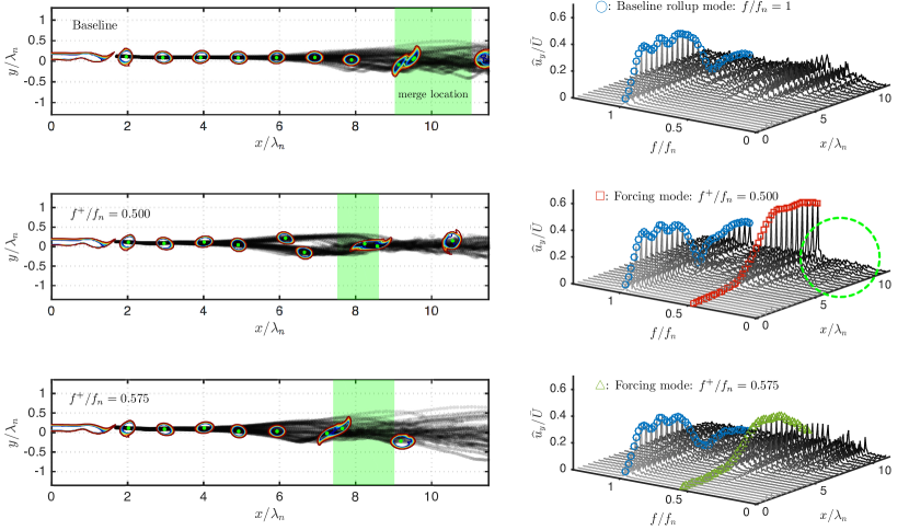
We start our detailed discussion on cases with . The baseline and forced flows are compared in figures 10 and 10. It is found that the forcing is able to change the vortex dynamics by encouraging the merging downstream while keeping the momentum thickness unchanged in the region dominated only by fundamental roll-up. We first track the center of each individual vortex after roll-up using the -criterion. By tracking all formed vortices over a time span of roll-up periods, we visualize the vortex trajectories by black transparent dots and the contour lines for a representative instantaneous spanwise vorticity field in figure 10 (left). Observing the trajectories, it is clear that, as the vortices convect downstream, they spread away from the centerline () earlier upstream in the forced flows compared to the baseline case. This deviation from the centerline serves as an initiation for vortex merging process (Winant & Browand, 1974; Ho & Huang, 1982). While the vortex merging process takes place, the flow passes through a stage where a pair of vortices become vertically aligned, which then results in the steep spatial growth of the momentum thickness. For example, the controlled case with shows the vertical alignment to take place at . By observing the momentum thickness in figure 10 (left), we find that this steep growth indeed corresponds to where the trajectories demonstrate deviation from the centerline for each case. With forcing at these two frequencies, the momentum thickness does not exhibit any change to that of the baseline until this second growth takes place farther upstream compared to the baseline.
A merging criterion is set up such that two vortices are considered to be merged if their instantaneous mutual distance is less than . By setting this threshold , we show the average streamwise location along with the variation (standard deviation) of where merging takes place by the green-shaded regions for each case in figure 10 (left). Again, by comparing the shaded region from the forced cases with the baseline, it is found that the merging process completes upstream with reduced spatial variation. Observation made from the vortex tracking and mean flow momentum thickness both enable us to draw the conclusion that the forcing is able to change the vortex dynamics by encouraging the merging downstream while keeping the momentum thickness unchanged in the region dominated only by fundamental roll-up.
Since the vortex merging process is dominated by the subharmonics of the roll-up frequency, we now examine the flow over the frequency domain and focus on low frequency components with . The transverse velocity spectra along the centerline are shown in figure 10 (right) for each corresponding case on the left. Comparing the forced cases to the baseline case, we find that the forcing mode in each forced case is amplified downstream, which suggests that both control inputs ( and ) are efficiently leveraging the shear layer instability. Moreover, the growth rates of these two forcing modes are both well predicted by the local stability analysis as previously depicted in figure 5. The energy distribution among the spectra does not show noticeable change from the baseline case until these two forcing modes start to be amplified at , as shown in figure 10. As discussed in Section 3.3, this streamwise station is in the isolated vortex region with linear perturbation growth. This location also corresponds to where momentum thickness starts to depart from that of the baseline with forcing, as seen in figure 10 (left). The excited low-frequency instability wave induced by the periodic heating accelerates the emergence of the vortex merging process within the shear layer. This observation agrees with those from the experimental study by Ho & Huang (1982) and the numerical simulation by Kourta et al. (1987).
Next, we shift our attention to the difference between forcing effects with and . In figure 10 (left), even though in both forced cases the vortex starts to deviate from centerline earlier than it does in baseline flow, the deviation takes place earlier for the case than the case. Correspondingly, the merging location is also farther upstream with . Moreover, the second growth in momentum thickness is also taking place earlier with as shown in figure 10 (left). Such observations can be explained by the greater growth rate in the forcing mode that both predicted by stability analysis and exhibited in figure 10 (right). The vortex merging process takes place in a more repetitive manner when forcing is introduced at the frequency with higher growth rate, leading to a lower variation in the vortex merging location visualized by the narrower green shaded region for . By observing all merging process identified by our criterion and examining all collected flow field snapshots, we find of vortices are not paired with any other vortices with , whereas there are only of vortices not going through pairing process in the streamwise window of .
After the vortices undergo merging, on the other hand, vortex trajectories exhibit less vertical variation in the subharmonic forced case than they are in the case with . These observations also agrees with those in the development for momentum thickness. The profiles also appears to be thinner for for the case with . By examining the spatial evolution of spectra in figures 10 (right) and 10 (right), we find that, even though the amplitude decay in roll-up mode takes place upstream compared to the baseline case for both forced cases, the case shows a faster decay rate than case does. The forcing mode for maintains its high level of modal amplitude while marching downstream, and suppresses other lower frequency modes to grow, as highlighted by the cleaner spectra in the green circled region compared to those of both baseline and cases in figure 10 (right). This reduction is due to the lower spillage from the modal energy at the forcing frequency. Since the growth of other low frequency modes keeps the shear layer to spread downstream, the relatively flat region in momentum thickness in subharmonic forced case can also be attributed to the absence of these lower frequency modes, as shown in figure 10 (left).
As pointed out in section 4, the thermal actuation can produce oscillatory vorticity flux over the trailing edge. This extra fluctuating vorticity generation is in turn fed to each formed vortex and leads to the variation in its strength from one vortex to another. This is shown in figure 11, where normalized circulation at each streamwise station is averaged over each formed vortex. We observed that, in both forced cases, the mean vortex strength does not significantly change from that of the baseline, but the variation in strength is larger. The variation in vortex strength can tip over the spatial balance from one vortex to another, resulting in its trajectory deviation from the centerline. The spread of shear layer can be attributed to both the random trajectory deviation and vortex merging process. As the strength variation in is greater than , the trajectory deviation and merging are indeed taking place earlier for than for .
The forcing effects with and in cases of initial momentum thicknesses, and are qualitatively similar to cases of discussed above. Additional discussions for these two cases are provided in appendix B.
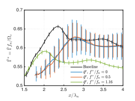
5.2 Excitation of fundamental roll-up ()
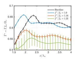
Let us discuss the forcing effects when the forcing frequency is close to with the use of (equation 5). We consider forcing frequencies of , and with and . All cases presented in this section are of the same forcing power of . Although we have also studied forced flow with forcing frequency up to , no significant change in the forced two-dimensional shear layer is observed for cases with .
Shown in figure 12 is the transverse velocity spectra for the baseline and forced cases with , and at a streamwise station of on the centerline. As discussed in Section 3, the stronger wake effect in baseline flow leads to a less synchronized shear layer roll-up and a spectrum with broader distribution of energy across frequencies. With periodic heating at frequencies considered here, we find that the forcing is able to lock the roll-up onto the forcing frequency, indicated by the prominent peaks at the corresponding forcing frequency for each case for both and in figure 12.
Analogous to the discussion for low-frequency forced cases, in figures 14 and 14 we show the vortex trajectories and spatial revolution of transverse velocity spectra and momentum thicknesses for baseline and three forced cases. The thermal forcing input serves as an excitation to the fundamental instability wave and encourages the shear layer roll-up at the forcing frequency. In cases with and , the thermal forcing results in the earlier shedding than that of the baseline. This can be seen by comparing the instantaneous vorticity contours in the initial shedding region: in both cases of and , the vorticity sheet formed from start to carry streamwise instability wave earlier than the baseline. Earlier roll-up can also be identified from the first rapid growth of in figure 14 (left).
| \begin{overpic}[scale={0.535}]{Figures/fig12a} \end{overpic} | \begin{overpic}[scale={0.535}]{Figures/fig12b} \end{overpic} |
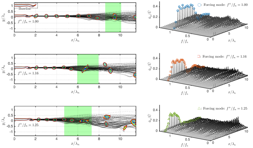
With , the synchronized shear layer roll-up due to forcing can also be observed from the uniform spacing between each vortex in the vortex train, as show in figure 14 (left). Also, the forcing is able to suppress the vortex deviating from the centerline. This leads to an extended isolated vortex region with forcing, suggested by the wider flat region in in figure 14 (left).
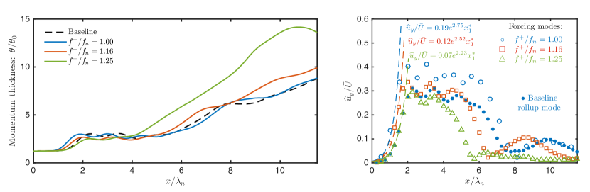
The spatial development of the frequency spectra and the modal amplitude growth are shown in figures 14 (right) and 14 (right), respectively. For the three forced cases, the amplitudes of the modes with their frequencies corresponding to the actuation frequencies start to grow immediately behind the trailing edge at , and their growth rates are well predicted by the local stability analysis, as shown in figure 14 (right). When the forcing frequency departs farther from , the growth rate decreases as observed for . This can be attributed to the instability characteristics of the shear layer. When the forcing frequency is closer to , the frequency with the highest spatial growth rate for the perturbation, the forcing effort grows faster since the growth rate is approaching its maximum.
The frequency spectra of the three forced cases all have distinct peaks at the forcing frequency initially for . As , lower frequency modes start to grow and the momentum thickness increases accordingly in figure 14 (left). With higher , the modal amplitude at the corresponding forcing frequency also decays spatially earlier in . Earlier decay of the modal amplitude at the forcing frequency also coincides with to the earlier growth of lower frequency modes in the full spectra in figure 14 (right). Especially for the case of , lower frequency modes start to develop farther upstream compared to the baseline flow, resulting in a faster second growth of .
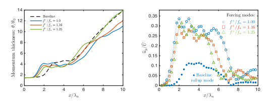
In the isolated vortex region for the forced cases, thinner is observed when using higher . This can be explained by the weaker vortex strength considering that the total vorticity flux is introduced from the inlet boundary at the same rate. With these compact vortices convecting at the mean shear layer velocity, the higher vortex passage frequency leads to lower amount of vorticity being possessed by the individual vortices, which can be confirmed from figure 15. For the cases with and , the mean vortex strengths are lower than those from the baseline and cases. With weaker vortices, the reduced mixing of momentum from two streams leads to the thinner momentum thickness in the isolated vortex region. Also, the strength variations in cases of and are greater than that of the baseline. This again leads to a faster shear layer spreading than the baseline, similar to the low frequency forced cases. With , on the other hand, the smaller variation in vortex strength leads to a more stable isolated vortex region, leading to the wider streamwise extent than that of the baseline as shown in figure 14 (left).
For cases with , the lock-on of shear layer roll-up frequency and extended isolated vortex region are still observed when forcing is invoked with , and , as shown in figure 12 and 16. However, we also note that for cases, no significant changes can be seen in the shear layer for , , even when using a forcing amplitude of , four times of the value considered earlier in this section.
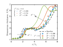
5.3 Roll-up delay (positive-mean heating)
In this section, forcing effects in the shear layer from using (equation 6) is investigated. This form of forcing, , is composed of a positive DC offset added to the oscillatory . The positive DC offset introduces net positive heat transfer from the actuator and raises the mean temperature of the fluid adjacent to the actuator. With the temperature-varying viscosity model discussed in appendix 2.2, this locally increased temperature leads to a higher viscosity.
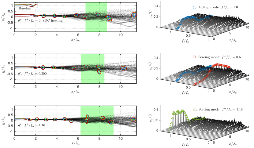
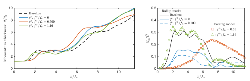
We consider representative forced cases with . The effects of the locally increased viscosity is shown in figure 18 (left). Comparing the cases with (i.e., constant heating) and to the baseline, the shear layer roll-up is delayed due to the locally increased viscosity. The delayed shear layer roll-up leads to an elongated recirculation region behind the trailing edge and introduces a stronger wake effect. As a consequence, the roll-up is observed to be less synchronized, as depicted in figure 18 (right) by the less prominent peak in the roll-up mode in the spectra of the DC heating and cases. The growth in the roll-up mode is also observed to reach a lower maximum amplitude than it does in the baseline flow, as show in figure 18 (right). With the stronger wake effect and the less synchronized roll-up, the vortex strength exhibits greater variation, as shown in figure 19. By the same mechanism discussed in the previous sections, the higher variation leads to the early deviations of the trajectories from the centerline, as well as the early merging of the vortices. Both of these effects cause the shear layer to spread faster downstream in the cases with DC heating and . The delayed roll-up and accelerated spreading can also be observed in the growth of from figure 18 (left). With the subharmonic forcing added, the case exhibits a greater growth in compared to the DC heating case. In the case with , the oscillatory component of dominates over the DC component and still accelerates the shear layer roll-up. The changes in the vortex trajectories (figure 18 (left)), vortex strength (figure 19), growth (figure 18 (left)) and the forcing mode growth (figure 18 (right)) show similar traits to those observed in the case using with .
In the subharmonic forced case with , the accelerated merging built upon the delayed roll-up draws additional interests. Motivated by the observation, for cases of DC heating and , we further examine the effects of the forcing amplitude, , in the growth of , as shown in figure 20. We observe that the shear layer roll-up location, suggested by the first growth in , is delayed farther downstream with increased , in both DC heating and subharmonic forced cases. Meanwhile, the acceleration in the spreading (second growth of ) is also enhanced by the subharmonic forcing with increasing .
Comparing the forcing effects of and , we observe that the oscillatory components from both type impose similar forcing effects to the shear layer. The positive DC component in is able to delay the shear layer roll-up when it is not excited by the oscillatory component.
6 Concluding remarks
We numerically examined the effectiveness of local periodic heating for modifying a spatially developing shear layer downstream of a splitter plate. The early evolution of the baseline shear layer is characterized by three regions; namely, the region where vortices rolls up, the second region where vortices advect along the centerline, and the third region where vortices deviate from the centerline, leading to the merging process. The periodic heating from the trailing edge introduces a thermal perturbation to the fluid adjacent to the actuator, and consequently generates oscillatory vorticity flux over its surface and baroclinic torque in its vicinity. These added sources of vorticity perturb the strength of the vortices formed from the shear layer roll-up, and result in the change in the shear layer dynamics.
This thermal actuation technique is shown to be capable of serving as an excitation source to both the fundamental and subharmonic instabilities. When using the forcing frequency close to the first subharmonic of the shear layer roll-up frequency, the forcing can encourage vortices to deviate from the centerline and accelerate the merging process. When the periodic heating excites the shear layer roll-up, such forcing is able to shift the roll-up frequency to the actuation frequency, and modify the mean strength of each vortex. The local momentum thickness in the isolated vortex region is also accordingly modified before further spreading takes place. The thermal actuation with positive-mean is also observed to delay the shear layer roll-up. In spite of the delayed roll-up, the subharmonic oscillatory component is still able to accelerate the downstream spreading of the shear layer. We also find that the shear layer spreading rate can be characterized by the synchronized nature of the shear layer roll-up. The lower level of roll-up synchronization correlates with the greater variance in the vortex strength, less repeatable vortex trajectories, and higher spreading rate of the shear layer.
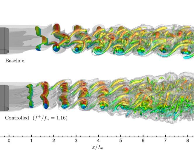
As a final note, let us briefly mention that the same control setting is observed to be effective in modifying three-dimensional free shear layers. We perform large-eddy simulations (LES) using the same setup as in 2D simulations but extend the computational domain in the spanwise direction with the extent of with spanwise periodicity. Shown in figure 21 is the instantaneous flow field, visualized using the isosurface of -criterion and vorticity magnitude, for the baseline and a controlled case of . For the controlled case, the excitation of shear layer roll-up instability is still effective in modifying the 3D shear layer with . Also, the enhanced shear layer spreading can also be observed in the flow visualization, as indicated by the wide transverse extent of the vortical structure in the controlled case compared to the baseline flow. While the use of present control approach requires further investigation in 3D turbulent flow, the shown result exhibits promising capabilities of the present actuation technique. In fact, this type of actuation has been shown to be effective in suppressing turbulent separated flow at a chord-based Reynolds number of over a canonical airfoil in another study by the current authors (see Yeh et al., 2017), showing the potential of thermal-based flow actuation in aerodynamic flow control applications.
We demonstrated that the nonlinear dynamics of a spatially developing shear layer can be modified by local oscillatory heat flux as a control input. This thermal-energy-deposition-based actuation is able to trigger the shear layer instability without relying on mass or momentum injections, and can be considered as a potential candidate for flow control actuation mechanism for a range of applications, especially for those that do not permit internal installation space for the actuators or sizable weight additions. We believe that this study provides a foundation for flow control using modern thermal-energy-based actuators.
The authors acknowledge the U.S. Army Research Office for supporting this project (Award Number W911NF-14-1-0224). The computations were supported by the High Performance Computing Modernization Program at the Department of Defense and the Research Computing Center at the Florida State University.
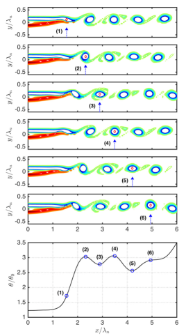
Appendix A Spatial oscillation in momentum thickness over the isolated vortex region
This spatial variation in the momentum thickness profile in the isolated vortex region is due to the changing orientation of the elliptic vortices. This spatial evolution in the vortex orientation is illustrated in figure 22 with six snapshots of instantaneous vorticity field (top) and the momentum thickness profile (bottom) with the spatial oscillation. Note that the flow fields are visualized in equal aspect ratio in both streamwise and transverse directions. We clearly observe that, at stations (3) and (5), the vortex is horizontally stretched, and the profile exhibits local minimum. On the other hand, at stations (2), (4) and (6), the vortex appears circular in shape and results in thicker .
Appendix B Subharmonic forced cases for and
We find noteworthy effects with subharmonic forcing using in the case with , as shown in figure 23 (left). Even though the vortex starts to deviate from the centerline earlier in both of the forced cases compared to the baseline, the vortex merging process takes place in a more repetitive (locked) manner when forcing is introduced at the first subharmonic of the roll-up frequency. The ordered and repetitive trajectories in leaves a white region absent of any trajectories around , where no vortices have traveled through. The use of subharmonic frequency allows for vortex merging by successive pairs along the vortex train. Also, after merging, vortex trajectories show significant reduction in their variations in the subharmonic forced case than in the case. The growths of the modal amplitudes is shown in figure 24 (bottom), where the modal amplitudes at both forcing frequencies are amplified downstream. The modal amplitude at the forcing frequency in case maintains its high level while marching downstream, and suppresses other lower frequency modes to grow, as highlighted by the clean spectra in the green circled region, compared to the baseline and cases in figure 23 (right), due to reduced spillage of the modal energy at forcing frequency. Since the growth of other low frequency modes keeps the shear layer spreading downstream, the slower growth in , as shown in figure 24 (top) for both cases, can also be attributed to the absence of these lower frequency modes.
 |
 |
References
- Abe et al. (2008) Abe, T., Takizawa, Y., Sato, S. & Kimura, N. 2008 Experimental study for momentum transfer in a dielectric barrier discharge plasma actuator. AIAA Journal 46 (9), 2248–2256.
- Adamovich et al. (2012) Adamovich, I. V., Little, J., Nishihara, M., Takashima, K. & Samimy, M. 2012 Nanosecond pulse surface discharges for high-speed flow control. In AIAA Paper 2012-3137.
- Akins et al. (2015) Akins, D., Singh, A. & Little, J. 2015 Effects of pulse energy on shear layer control using surface plasma discharges. In AIAA Paper 2015-3344.
- Aleksandrov et al. (2010) Aleksandrov, N. L., Kindysheva, S. V., Nudnova, M. M. & Starikovskiy, A. Yu 2010 Mechanism of ultra-fast heating in a non-equilibrium weakly ionized air discharge plasma in high electric fields. Journal of Physics D: Applied Physics 43 (25), 255201.
- Arnold & Crandall (1917) Arnold, H. D. & Crandall, I. B. 1917 The thermophone as a precision source of sound. Physical Review 10 (1), 22.
- Barone & Lele (2005) Barone, M. F. & Lele, S. K. 2005 Receptivity of the compressible mixing layer. Journal of Fluid Mechanics 540, 301–335.
- Bechert (1988) Bechert, D. W. 1988 Excitation of instability waves in free shear layers. part 1. theory. Journal of Fluid Mechanics 186, 47–62.
- Bechert & Stahl (1988) Bechert, D. W. & Stahl, B 1988 Excitation of instability waves in free shear layers. part 2. experiments. Journal of Fluid Mechanics 186, 63–84.
- Bin et al. (2015) Bin, Jonghoon, Oates, William S & Taira, Kunihiko 2015 Thermoacoustic modeling and uncertainty analysis of two-dimensional conductive membranes. Journal of Applied Physics 117 (6), 064506.
- Brès et al. (2017) Brès, G. A., Ham, F. E., Nichols, J. W. & Lele, S. K. 2017 Unstructured large-eddy simulations of supersonic jets. AIAA Journal .
- Brown & Roshko (1974) Brown, G. L & Roshko, A. 1974 On density effects and large structure in turbulent mixing layers. Journal of Fluid Mechanics 64 (04), 775–816.
- Cattafesta et al. (2008) Cattafesta, L. N., Song, Q., Williams, D. R., Rowley, C. W. & Alvi, F. S. 2008 Active control of flow-induced cavity oscillations. Progress in Aerospace Sciences 44, 479–502.
- Cheung & Lele (2009) Cheung, L. C. & Lele, S. K. 2009 The dynamics of nonlinear instability waves in laminar heated and unheated compressible mixing layers. Physics of Fluids 21 (9), 094103.
- Choi & Moin (2012) Choi, H. & Moin, P. 2012 Grid-point requirements for large eddy simulation: Chapman?s estimates revisited. Physics of Fluids 24 (1), 011702.
- Clemens & Mungal (1995) Clemens, N. T. & Mungal, M. G. 1995 Large-scale structure and entrainment in the supersonic mixing layer. Journal of Fluid Mechanics 284, 171–216.
- Corke et al. (2010) Corke, T. C., Enloe, C. L. & Wilkinson, S. P. 2010 Dielectric barrier discharge plasma actuators for flow control. Annual Review of Fluid Mechanics 42, 505–529.
- Corke et al. (2009) Corke, T. C., He, C. & Patel, M. 2009 Plasma flaps and slats: an application of weakly-ionized plasma actuators. Journal of Aircraft 46 (3), 864–873.
- Crighton (1985) Crighton, D. G. 1985 The Kutta condition in unsteady flow. Annual Review of Fluid Mechanics 17 (1), 411–445.
- Elliott & Samimy (1990) Elliott, G. S. & Samimy, M. 1990 Compressibility effects in free shear layers. Physics of Fluids 2 (7), 1231–1240.
- Freund (1997) Freund, J. B. 1997 Proposed inflow/outflow boundary condition for direct computation of aerodynamic sound. AIAA Journal 35 (4), 740–742.
- Garnier et al. (2009) Garnier, E., Adams, N. & Sagaut, P. 2009 Large eddy simulation for compressible flows. Springer Science & Business Media.
- Glezer & Amitay (2002) Glezer, A. & Amitay, M. 2002 Synthetic jets. Annual Review of Fluid Mechanics 34 (1), 503–529.
- Greenblatt et al. (2006) Greenblatt, D., Paschal, K. B., Yao, C.-S. & Harris, J. 2006 Experimental investigation of separation control part 2: Zero mass-flux oscillatory blowing. AIAA Journal 44 (12), 2831–2845.
- Gad-el Hak & Bushnell (1991) Gad-el Hak, M. & Bushnell, D. M. 1991 Separation control: review. Journal of Fluids Engineering 113 (1), 5–30.
- Ho & Huang (1982) Ho, C.-M. & Huang, L.-S. 1982 Subharmonics and vortex merging in mixing layers. Journal of Fluid Mechanics 119, 443–473.
- Ho & Huerre (1984) Ho, C.-M. & Huerre, P. 1984 Perturbed free shear layers. Annual Review of Fluid Mechanics 16 (1), 365–422.
- Hornung (1989) Hornung, H. 1989 Vorticity generation and transport. In 10th Australasian fluid mechanics conference, Paper KS-3.
- Khalighi et al. (2011a) Khalighi, Y., Ham, F., Moin, P., Lele, S., Schlinker, R., Reba, R. & J., Simonich 2011a Noise prediction of pressure-mismatched jets using unstructured large eddy simulation. Proceedings of ASME Turbo Expo, Vancouver.
- Khalighi et al. (2011b) Khalighi, Y., Nichols, J. W., Ham, F., Lele, S. K. & Moin, P. 2011b Unstructured large eddy simulation for prediction of noise issued from turbulent jets in various configurations. In AIAA Paper 2011-2886.
- Kourta et al. (1987) Kourta, A., Braza, M., Chassaing, P. & Haminh, H. 1987 Numerical analysis of a natural and excited two-dimensional mixing layer. AIAA Journal 25 (2), 279–286.
- Laizet et al. (2010) Laizet, S., Lardeau, S. & Lamballais, E. 2010 Direct numerical simulation of a mixing layer downstream a thick splitter plate. Physics of Fluids 22 (1), 015104.
- Lehmann et al. (2014) Lehmann, R., Akins, D. & Little, J. 2014 Effects of ns-DBD plasma actuators on turbulent shear layers. In AIAA Paper 2014-2220.
- Little et al. (2012) Little, J., Takashima, K., Nishihara, M., Adamovich, I. V. & Samimy, M. 2012 Separation control with nanosecond-pulse-driven dielectric barrier discharge plasma actuators. AIAA Journal 50 (2), 350–365.
- Mehta (1991) Mehta, R. D. 1991 Effect of velocity ratio on plane mixing layer development: Influence of the splitter plate wake. Experiments in Fluids 10 (4), 194–204.
- Monkewitz & Huerre (1982) Monkewitz, P. A. & Huerre, P. 1982 Influence of the velocity ratio on the spatial instability of mixing layers. Physics of Fluids 25 (7), 1137–1143.
- Nudnova et al. (2010) Nudnova, M. M., Aleksandrov, N. L. & Starikovskii, A. Y. 2010 Influence of the voltage polarity on the properties of a nanosecond surface barrier discharge in atmospheric-pressure air. Plasma Physics Reports 36 (1), 90–98.
- Papamoschou & Roshko (1988) Papamoschou, D. & Roshko, A. 1988 The compressible turbulent shear layer: an experimental study. Journal of Fluid Mechanics 197, 453–477.
- Popov (2011) Popov, N. A. 2011 Fast gas heating in a nitrogen–oxygen discharge plasma: I. kinetic mechanism. Journal of Physics D: Applied Physics 44 (28), 285201.
- Post & Corke (2004) Post, M. L. & Corke, T. C. 2004 Separation control on high angle of attack airfoil using plasma actuators. AIAA Journal 42 (11), 2177–2184.
- Sabatini & Bailly (2014) Sabatini, R. & Bailly, C. 2014 Numerical algorithm for computing acoustic and vortical spatial instability waves. AIAA Journal 53 (3), 692–702.
- Samimy et al. (2007) Samimy, M., Kim, J.-H., Kastner, J., Adamovich, I. V. & Utkin, Y 2007 Active control of high-speed and high-Reynolds-number jets using plasma actuators. Journal of Fluid Mechanics 578, 305–330.
- Seifert & Pack (1999) Seifert, A. & Pack, L. G. 1999 Oscillatory control of separation at high Reynolds numbers. AIAA Journal 37 (9), 1062–1071.
- Sharma et al. (2011) Sharma, A., Bhaskaran, R. & Lele, S. K. 2011 Large-eddy simulation of supersonic, turbulent mixing layers downstream of a splitter plate. In AIAA Paper 2011-208.
- Sinha et al. (2012) Sinha, A., Alkandry, H., Kearney-Fischer, M., Samimy, M. & Colonius, T. 2012 The impulse response of a high-speed jet forced with localized arc filament plasma actuators. Physics of Fluids 24 (12), 125104.
- Tian et al. (2011) Tian, H., Ren, T.-L., Xie, D., Wang, Y.-F., Zhou, C.-J., Feng, T.-T., Fu, D., Yang, Y., Peng, P.-G., Wang, L.-G. & Liu, L.-T. 2011 Graphene-on-paper sound source devices. ACS Nano 5 (6), 4878–4885.
- Vukasinovic et al. (2010) Vukasinovic, B., Rusak, Z. & Glezer, A 2010 Dissipative small-scale actuation of a turbulent shear layer. Journal of Fluid Mechanics 656, 51–81.
- Wiltse & Glezer (1998) Wiltse, J. M. & Glezer, A. 1998 Direct excitation of small-scale motions in free shear flows. Physics of Fluids 10 (8), 2026–2036.
- Winant & Browand (1974) Winant, C. D. & Browand, F. K. 1974 Vortex pairing: the mechanism of turbulent mixing-layer growth at moderate Reynolds number. Journal of Fluid Mechanics 63 (02), 237–255.
- Wu & Wu (1993) Wu, J.-Z. & Wu, J.-M. 1993 Interactions between a solid surface and a viscous compressible flow field. Journal of Fluid Mechanics 254, 183–211.
- Yeh et al. (2017) Yeh, C.-A., Munday, P. & Taira, K. 2017 Use of local periodic heating for separation control on a NACA 0012 airfoil. In AIAA Paper 2017-1451.
- Zhuang & Dimotakis (1995) Zhuang, M. & Dimotakis, P. E. 1995 Instability of wake-dominated compressible mixing layers. Physics of Fluids 7 (10), 2489–2495.