Nonparaxial Cartesian and azimuthally symmetric waves with concentrated wavevector and frequency spectra
Abstract
In this paper, we develop a theoretical analysis to efficiently handle superpositions of waves with concentrated wavevector and frequency spectra, allowing an easy analytical description of fields with interesting transverse profiles. First, we analyze an extension of the paraxial formalism that is more suitable for superposing these types of waves, as it does not rely on the use of coordinate rotations combined with paraxial assumptions. Second, and most importantly, we leverage the obtained results to describe azimuthally symmetric waves composed of superpositions of zero-order Bessel beams with close cone angles that can be as large as desired, unlike in the paraxial formalism. Throughout the paper, examples are presented, such as Airy beams with enhanced curvatures, nonparaxial Bessel-Gauss beams and Circular Parabolic-Gaussian beams (which are based on the Cartesian Parabolic-Gaussian beams), and experimental data illustrates interesting transverse patterns achieved by superpositions of beams propagating in different directions.
1 Introduction
Appropriate superpositions of waves propagating in different directions may create interesting and useful interference patterns in the transverse plane that keep their shape up to a certain propagation distance, which is the range within which the waves interfere significantly. Consequently, it is higher when the spot sizes of the superposed waves are bigger, which implies that their wavevector spectra are concentrated around their propagation directions. Since these can make large angles with respect to the longitudinal axis, the paraxial wave equation may not describe the propagation of the superposition properly.
In principle, each wave could be analyzed separately using the paraxial formalism in a system of rotated coordinates whose z-axis coincide with its propagating direction and the application of the inverse rotation would express the wave as a function of the desired non-rotated coordinates. However, this procedure is not straightforward and results in complicated expressions, as the rotations mix the transverse and longitudinal non-rotated coordinates.
To allow a more suitable and analytically simple way of handling superpositions of waves with concentrated spectra, we analyze and apply an extension of the paraxial formalism that deals with combinations of plane waves whose wavevectors are close to any desired direction without relying on coordinate rotations. The resulting expressions do not mix transverse and longitudinal coordinates while still incorporate the inclination of the plane waves very clearly through parameters. Moreover, if desired, the method can be straightforwardly extended to include higher-order corrections, so it is not limited to the accuracy of the paraxial approximation.
As the main contribution of this work, we then leverage these results to develop a novel analytical treatment for azimuthally symmetric waves with concentrated spectra, that is, waves composed of superpositions of zero-order Bessel beams with close cone angles. However, in contrast to the paraxial assumption of small angles with respect to the longitudinal axis, this formalism encompasses cone angles as large as desired and provides simple expressions for this class of nonparaxial waves. In particular, similarities with the unidimensional222We will say that a wave is n-dimensional when it is a function of n transverse spatial coordinates, in addition to the longitudinal coordinate and the time . Cartesian waves here analyzed allow us to build azimuthally symmetric versions of them, which can be used to derive new types of waves. As examples, we provide an analytical expression for nonparaxial Bessel-Gauss beams and for azimuthally symmetric versions of Parabolic-Gaussian beams (which we refer to as Circular Parabolic-Gaussian beams).
Throughout this work, we also present experimental demonstrations and comparisons to numerically-calculated Rayleigh-Sommerfeld diffraction integrals to corroborate the validity and accuracy of the theoretical results.
2 Integral formulation and wave equation
2.1 Bidimensional case
Let be an arbitrary solution of the homogeneous scalar wave equation . It can be represented by a superposition of plane waves with different wavevectors and angular frequencies , given that , where is the speed of light in the medium. If we consider only waves that propagate in the direction, and can be written as
| (1) |
where is the spectrum, which determines the amplitude and phase of each plane wave. The limits of the integrals in Eq. (1) allow imaginary values of , accounting for the presence of evanescent waves. If only propagating waves are desired, the integration should be performed in the region .
If the spectrum is concentrated around , the plane waves have wavevectors that vary only slightly around , where . Mathematically, this means that is significant only in the region in which , and , with , and being defined as the deviation variables 333Additionally, we may assume that , and , so that all the waves are propagating. In this case, even though we keep the limits of the integrals in and from to , the concentration of the spectrum implies that there are no significant evanescent waves in the superposition.. In this region, can be approximated to second order in and using a Taylor series expansion444If desired, higher-order corrections can be easily included to improve accuracy, even though the second-order approximation is usually enough.:
| (2) |
where . For the variation in , we perform a first order Taylor series approximation only in the most significant term, which is the first one on the right-hand side of Eq. (2), resulting in
| (3) |
In all the other terms, we take . Assigning names to the constants of Eq. (1) and Eq. (2):
| (4a) | |||
| (4b) | |||
| (4c) | |||
| (4d) | |||
where and
| (7) |
is the deviation of with respect to .
Eq. (5) shows that is approximately a plane wave with wavevector and frequency modulated by an envelope which, according to Eq. (6), is composed of a superposition of plane waves with wavevectors and angular frequencies . Since , , and are small compared to , , and , respectively, has slow variations in , , and . Mathematically, this means
| (8a) | |||
| (8b) |
where stands for any spatial coordinate.
The differential equation satisfied by is uniquely defined by the relation among the frequency and wavevector components of its composing plane waves, given by Eq. (7). Each differentiation of with respect to a variable implies a multiplication of its spectrum by a factor proportional to the corresponding reciprocal variable, resulting in the correspondences:
| (9) |
where stands for any spatial coordinate. Therefore, Eq. (7) is equivalent to
| (10) |
where and . The coefficient of the mixed derivative in Eq. (10) implies that the equation has separable solutions of the form only when , that is, when at least one of and is zero. If they are both zero, , , and and Eq. (10) reduces to the well-known paraxial wave equation , since in this case the superposed plane waves have wavevectors almost parallel to the z-direction.
2.2 Unidimensional case
If is a function of only one of the transverse coordinates, say , the same kind of analysis provides results similar to those of sec. 2.1:
| (11) | |||
| (12) | |||
| (13) | |||
| (14) |
with . In this case, it is possible to write Eq. (14) in a dimensionless form by defining new constants and dimensionless variables:
| (15) | |||
| (16) |
where is a constant. Then, the differential equation for becomes
| (17) |
When it correctly reduces to the dimensionless unidimensional paraxial wave equation .
Using these constants and dimensionless variables and defining the dimensionless wavevector , the wave of Eq. (11) can be written as
| (18) |
where is a concentrated spectrum around .
2.3 Reduction to the paraxial wave equation
By means of some changes of variables, it is possible to reduce the general Eq. (10) to the paraxial wave equation, so we can leverage all we know about this equation to Eq. (10). The first order derivatives in , and can be eliminated if we introduce the shifted variables , and according to
| (19a) | ||||
| (19b) | ||||
| (19c) | ||||
| (19d) | ||||
Applying the chain rule and defining , Eq. (10) can be rewritten as
| (20) |
Note that the shifts in the transverse coordinates express the inclination of with respect to the z-direction and the shift in the temporal variable represents the wave’s travel time to arrive at the longitudinal position . Eq. (20) shows that any solution of Eq. (10) must be of the form .
With an additional change of variables of the type
| (21) |
it is possible to eliminate the mixed derivative of the operator . Two alternatives that reduce it to are
| (22a) | ||||
| (22b) | ||||
and
| (23a) | |||
| (23b) | |||
so that Eq. (20) becomes
| (24) |
which is like a paraxial wave equation in the variables and . The factor was not changed to because, as already pointed out in sec. 2.1, if . However, if desired, an additional scaling in both and can reduce Eq. (24) precisely to the paraxial wave equation in the new scaled variables, which are and . In the unidimensional case, Eq. (14) may be reduced to and also obeys the paraxial wave equation in the scaled variable .
Therefore, any solution of the paraxial wave equation can be extended to the case being considered, which is natural, since this approach should be analogous to a rotation of coordinates. Note, however, that the former is simpler: while the rotation expresses the coordinate as a combination of both transverse and longitudinal rotated coordinates, the presented method keep the transverse and longitudinal coordinates separated.
The choice of Eq. (22) for and , although asymmetrical in and , reduces to and when the “coupling factor” is zero, showing that the lack of the mixed derivative makes it possible to find a separable solution for in the variables and . The choice of Eq. (23), on the other hand, has a better symmetry in and , but reduces to and when .
Also, note that if a beam with envelope satisfies Eq. (10), the pulse with envelope is also a solution of that equation for an arbitrary differentiable function .
3 Diffraction integral
For waves with concentrated spectrum around it is possible to derive a generalization of the Fresnel diffraction integral.
3.1 Bidimensional case
From Eq. (6), it is evident that is a Fourier transform of . Therefore, by inverting the transform, we have
| (25) |
Substituting Eq. (25) in Eq. (6), the integrals in , and can be solved by completing squares and using the known results and , where is the Dirac delta function. This leads to the diffraction integral:
| (26) |
For beams, that is, when is not a function of time, Eq. (26) is still valid if we remove the dependencies. As it should be, for it reduces to the Fresnel diffraction integral. An alternative procedure to derive Eq. (26) is to write the Fresnel diffraction integral for the transformed variables and and arrange the terms in and .
3.2 Unidimensional case
An analogous procedure starting with Eq. (12) results in
| (27) |
4 Helmholtz-Gauss beams
Since satisfies Eq. (24), which is exactly a paraxial wave equation with replaced by , there exists a corresponding Helmholtz-Gauss beam with envelope given by [7]
| (28) |
where 555Note that for the paraxial wave equation and we have to replace with to be consistent with Eq. (24)..
Using the transformation of Eq. (22), the envelope is expressed in the original Cartesian coordinates by
| (29) |
Note that, as and are linear combinations of , and , can be expressed as . At , we have
| (30) |
which is a Gaussian apodization with an extra mixed-product term proportional to .
5 Nonparaxial linearly polarized electromagnetic field with concentrated spectra
Since any Cartesian component of an electric field obeys the scalar wave equation, a scalar wave with concentrated spectra can be assigned to one of them and the other field components can be obtained via Maxwell’s equations.
If we choose a linearly polarized electric field in the x-direction with
| (31) |
the component is given by Gauss’s law (), which implies
| (32) |
Integrating by parts when is in the integrand and using its slow variation (Eq. (8a)) to write (where can be any spatial coordinate), we find that
| (33) |
6 Examples of Cartesian solutions
6.1 Gaussian pulse with Gaussian bidimensional spatial profile
If we choose a separable Gaussian spectrum in , and :
| (35) |
where is an arbitrary constant and , and are related to the spot sizes in , and , respectively, and use the integral result , valid for [6], Eq. (5) and Eq. (6) give
| (36) |
6.2 Unidimensional Gaussian beam (GB)
For a single frequency () and a Gaussian spectrum in :
| (37) |
the resultant wave is a unidimensional Gaussian beam (GB):
| (38) |
6.3 Nonparaxial Cartesian Parabolic-Gaussian (PG) beams
The solutions of the paraxial wave equation known as Cartesian Parabolic-Gaussian (PG) beams were introduced by Bandres et al. in [3] and further analyzed in [8]. Their envelope is described by
| (39) |
with
| (40) | |||
| (41) | |||
| (42) | |||
| (43) |
where is the Rayleigh distance, is the waist of the Gaussian envelope, is for even beams and for odd beams, is the order of the parabolic cylinder function , is the confluent hypergeometric function and is a real parameter. At , it becomes
| (44) |
To obtain the nonparaxial version of this envelope, is is only necessary to replace by , as explained in sec. 2.3.
Although the previous nonparaxial examples are just inclined versions of the usual paraxial beams, they are useful for describing superpositions of beams (as commented in sec. 7) and for generating new expressions for azimuthally symmetric waves (as shown in sec. 9 and exemplified in sec. 10). However, it is also possible to use the presented formalism to obtain waves with enhanced characteristics with respect to their paraxial counterparts, as illustrated in the next example.
6.4 Nonparaxial Airy Beam
The spectrum
| (45) |
with free real parameters , and results in a nonparaxial Airy beam. causes a Gaussian apodization of the spectrum, which is manifested in space as an exponential apodization of the Airy spatial profile at . As in the paraxial case, the spectrum is not concentrated unless the beam is apodized.
Using the integral result [11], the expression of the beam becomes
| (46) |
Denoting , the parabolic trajectory of the beam’s position of maximum amplitude is
| (47) |
since is where has its maximum value. Therefore, controls the linear coefficient and , the independent coefficient. If we choose , and , the trajectory equation becomes simply
| (48) |
or, as a function of and ,
| (49) |
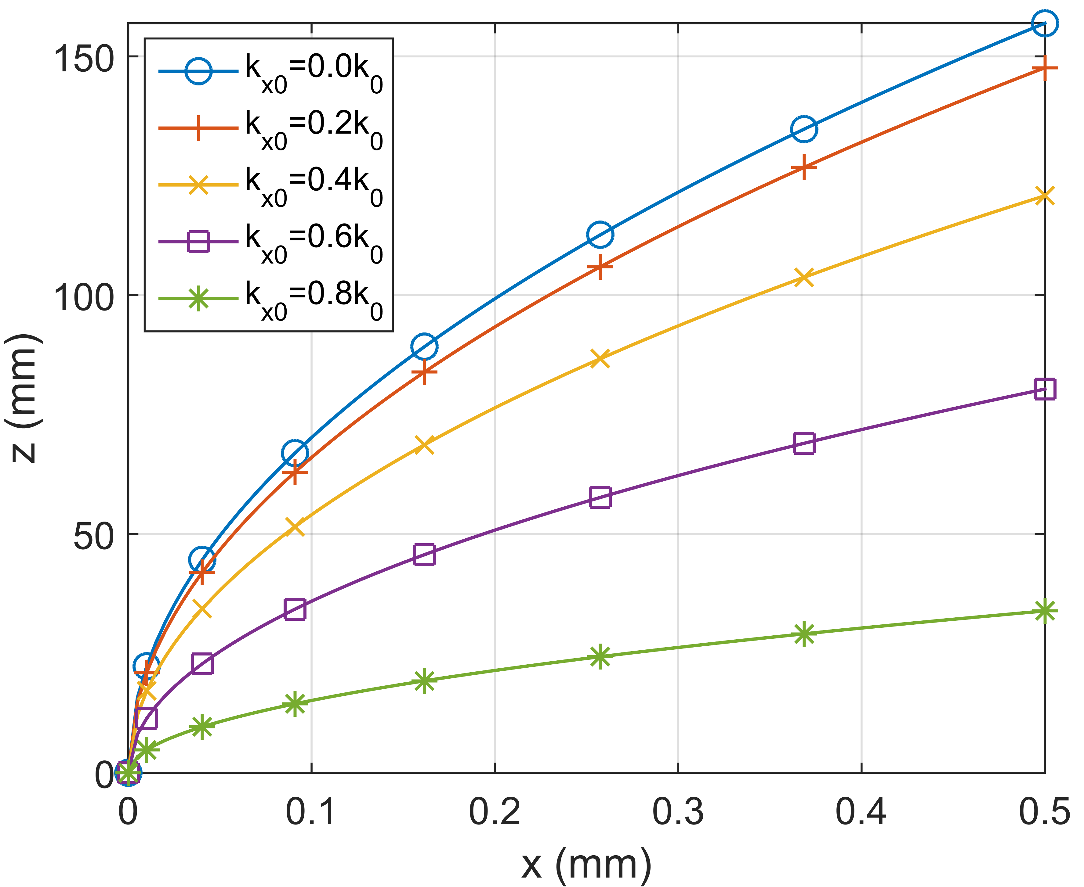
While controls the spot size of the beam, can be used to choose a desired curvature for its trajectory. To illustrate this, Fig. 1 shows the variation of the beam’s curvature when is varied for .
7 Symmetric superposition of Cartesian waves
As explained in the introduction, the basic goal of the analysis so far is to provide a simple analytic way to describe the propagation of a superposition of waves traveling in different directions, thus composing interesting interference patterns in the transverse plane. Although these waves obey different approximate equations, since their dissimilar and give rise to different constants in Eq. (10), they are all approximate solutions of the homogeneous scalar wave equation, which implies that their expressions can be legitimately combined.
Let’s take as an example the superposition of two equal unidimensional beams with the same initial envelope traveling in opposite directions so that the resulting wavevector spectrum has peaks concentrated both at and 666Note that, according to sec. 2.3, is a function of and and, at , . Since is the same for and , the initial envelope is equal for the two beams.. Applying the diffraction integral (Eq. (27)) for each beam and combining the results, we have
| (50) |
where is related to . After expanding the squares and rearranging the terms, the result is
| (51) |
At the initial plane , the simple superposition of the two patterns gives
| (52) |
showing that the slowly-varying envelope is modulated by the fast-oscillating function . Therefore, the spot radius of the resulting beam is determined by a quarter of this cosine period, that is, .
In any superposition, the resulting field depth can be estimated by the distance within which the waves interfere significantly. In this simple case, we can apply a reasoning analogous to that of the upcoming sec. 9.4 to obtain , where is a characteristic width of the envelope .
8 Experimental results
To demonstrate that the proposed theoretical expressions can be used to easily describe a superposition of beams with concentrated spectra propagating in different directions, we experimentally generated two superpositions of Gaussian beams that result in illustrative interference patterns. The experimental setup is shown in Fig. 2 and used a reflective Spatial Light Modulator (SLM) to generate the desired patterns.
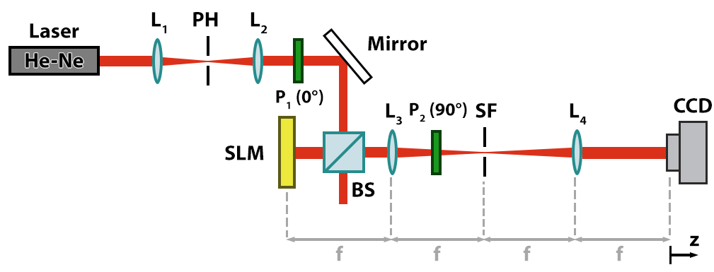
A He-Ne laser () is expanded and collimated by a system of lenses ( and ) and then sent to the SLM, which is a LC-R1080 model from Holoeye Photonics and possesses a display matrix of 1920x1200 with pixel size. The device was used in amplitude modulation mode, with the polarizer and analyzer angles ( and , respectively) measured with respect to the SLM axis. The reflected beam is then subject to a 4f spatial filtering system. The SLM is positioned at the input plane (at a focal distance behind the lens ) and the spatial filtering mask (SF, a band-pass circular pupil) is placed at the Fourier plane to select the first diffraction order containing the information of the desired complex field pattern. After another Fourier transform, the field is obtained at the Fourier plane of lens and its intensity profile for different propagation distances is measured by a CCD camera (DMK 41BU02.H from The Imaging Source, with a 1280x960 display and pixel size).
Due to the size of the SLM’s pixel, it cannot resolve well the fast amplitude and phase variations of beams with and/or ratios that are not small, so we had to choose close-to-zero values for them. Even though these beams are not significantly nonparaxial, the results illustrate how interesting interference patterns can be produced. With suitable equipment, it is straightforward to generate the same kinds of beams in a nonparaxial regime.
8.1 Superposition of two Gaussian beams
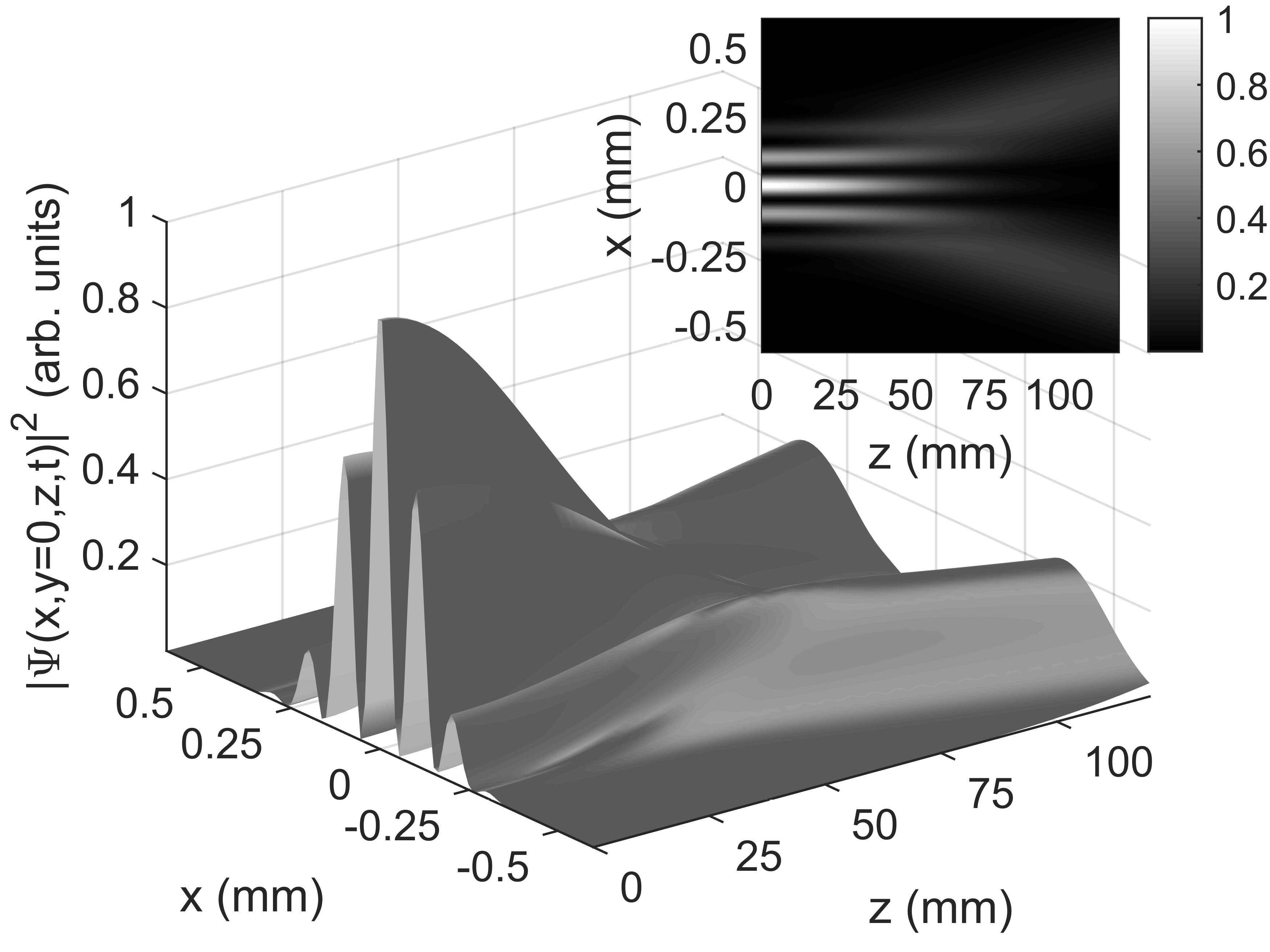
The first example consists in a superposition of two Gaussian beams with same amplitudes and spot sizes , but with different values of and . One of them has and the other has , so that they propagate in opposite directions in the -axis but do not shift in the -direction. Fig. 3 shows what we should expect for a cut of the beam’s intensity profile: a sinusoidal pattern enveloped by a Gaussian function. Therefore, it can be viewed as a kind of “cartesian analog” of a Bessel-Gauss (BG) beam, which consists in a superposition of GBs over a cone and has a Bessel function profile enveloped by a Gaussian function.
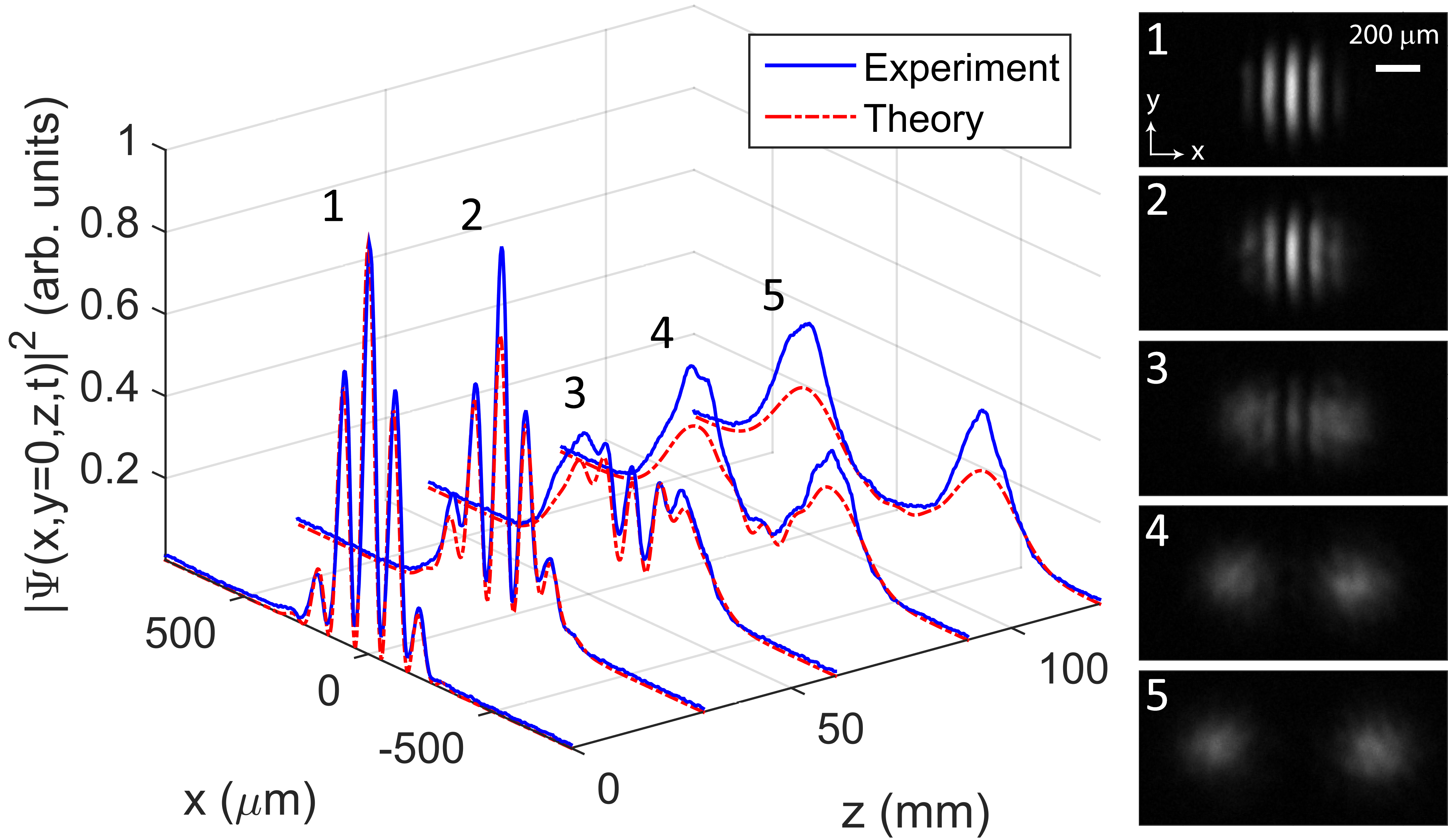
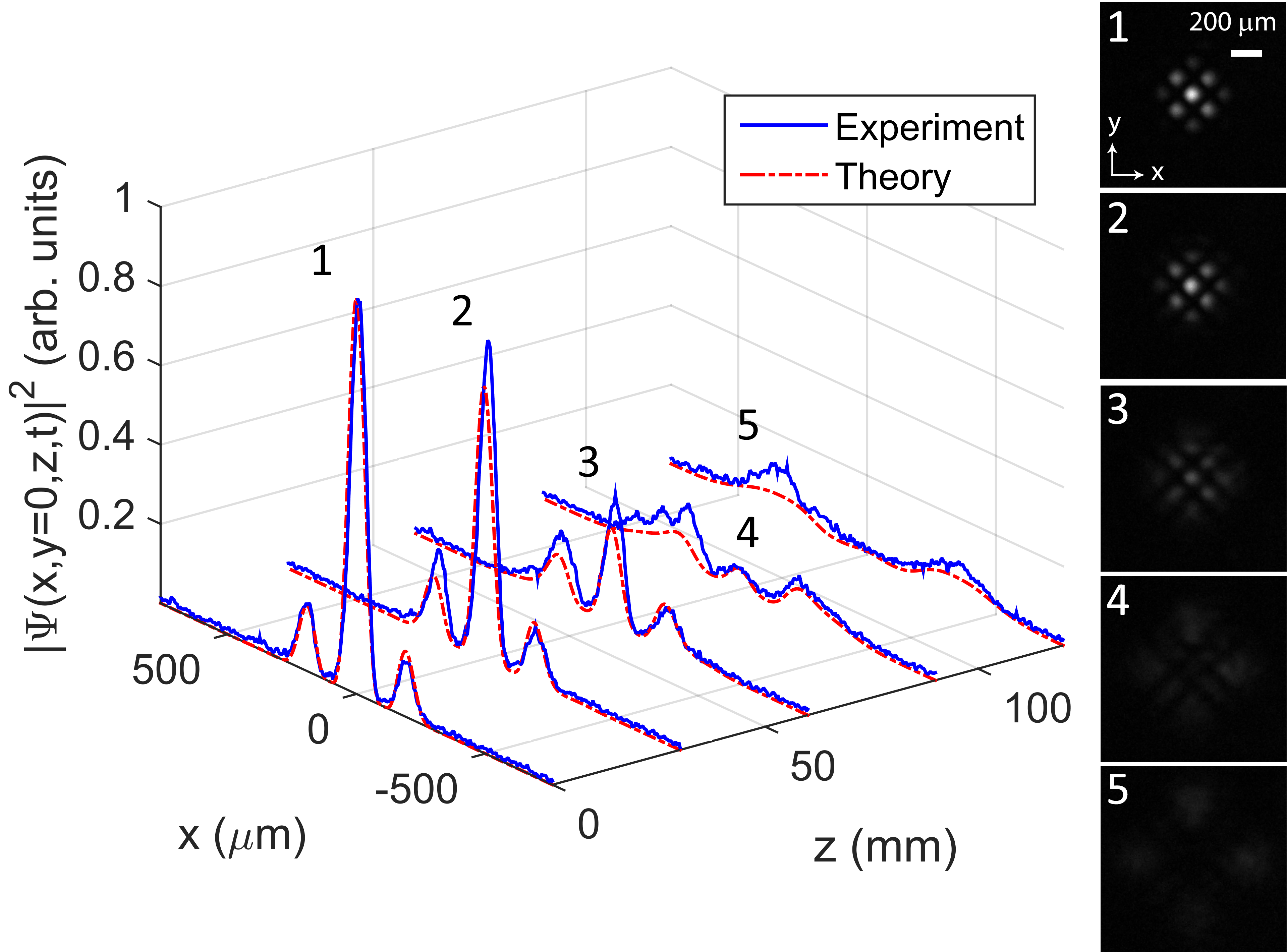
The propagation distance for which the sinusoidal pattern is kept can be estimated by the expression in sec. 7, resulting in , which agrees with Fig. 3. Fig. 4 shows the good agreement between the theoretical and the measured intensity patterns for cuts at different propagation distances and also presents the measured patterns for each of these positions.
8.2 Superposition of four Gaussian beams
The second example consists in a superposition of four Gaussian beams with same amplitudes and spot sizes , but with different values of and . Two of them are the same as the ones in sec. 8.1 and the other two have and , so that, in addition to the two beams being shifted in the x-direction, we now have two more beams that are shifted along the y-axis in opposite directions. Therefore, the interference pattern will be a little more sophisticated, with more maxima and minima than the one in sec. 8.1.
Fig. 5 shows the good agreement between the theoretical and measured intensity patterns for cuts at different propagation distances and also presents the measured patterns for each of these positions.
9 Nonparaxial azimuthally symmetric waves with concentrated spectra
Following a procedure similar to the one in sec. 2, we now present how the previous unidimensional results can be leveraged to describe nonparaxial azimuthally symmetric waves with concentrated spectra.
9.1 Superposition of Bessel beams with close cone angles
Any azimuthally symmetric wave can be expressed as a superposition of Bessel beams of order zero, that is
| (53) |
with the spectrum defining the amplitudes of each beam. Note that the upper limit of is not limited to , so that evanescent waves are allowed.
For an arbitrary spectrum, the integrals in Eq. (53) generally do not have a closed analytical representation, but when is concentrated around some simplifications can be applied using an approximate expression for . As in sec. 2.1, a concentrated spectrum means that is significant only inside the region and , where and . In other words, all the superposed Bessel beams have almost the same cone angle. Note, however, that it can be as large as desired, unlike in the paraxial approximation, which restricts the angle to small values.
Similarly to what was done in sec. 2, the hypothesis of concentrated spectrum allows us to accurately approximate to second order in and to first order in :
| (54) |
In this expression, the constants are defined as:
| (55a) | |||
| (55b) | |||
| (55c) | |||
Changing the integration variable in Eq. (53) from to , the result is
| (56) |
with and
| (57) |
For , the spectrum is concentrated around and its amplitude is negligible in the region . Therefore, the lower limit of the integral in in Eq. (56) can be extended to without loss of accuracy.
9.2 An approximate expression of
Now, we will make use of an unusual, although very accurate, approximate expression for . It was first introduced in [9], but the reasoning behind its derivation was not presented. Therefore, we show here how this approximation is obtained.
The asymptotic approximation for is [2]
| (58) |
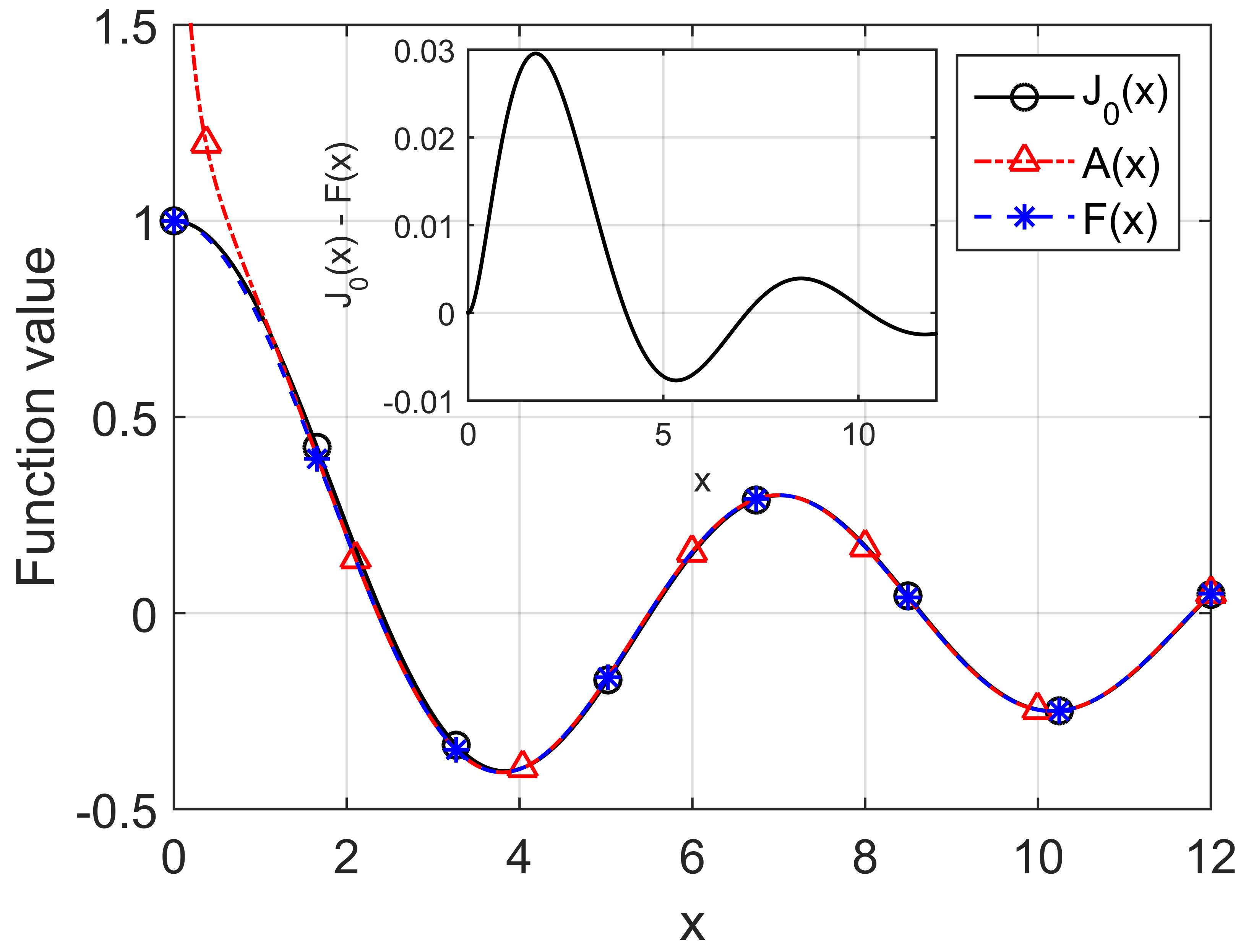
Although it is rigorously valid only when the argument is large, Fig. 6 shows that this asymptotic approximation is precise even for relatively small values of , failing only due to the divergence when . Therefore, one could attempt to improve the accuracy of Eq. (58) for small arguments by introducing a function in the denominator of the square root to eliminate the divergence, that is,
| (59) |
where is chosen in such a way that for all . To this end, must have the following properties:
-
•
, so that .
-
•
, so that .
-
•
sufficiently fast when increases, so that for .
The simplest function that satisfies all these conditions is and we can hence accurately approximate with the expression
| (60) |
for any , even small. To allow negative arguments, in the right-hand side of Eq. (60) should be replaced by , so that the expression is even, as is . Fig. 6 displays a comparison between the exact , the asymptotic approximation and the unusual approximation, showing that the latter represents very accurately.
It is worth noting that the approximation in Eq. (60) for separates the slowly-decaying envelope from the fast oscillations expressed by .
9.3 Similarities with the unidimensional Cartesian case
Extending the lower limit of the integral in Eq. (56) to and using the approximation for the Bessel function, the expression becomes
| (61) |
Since by hypothesis where is significant, the argument of the Bessel function is always positive in this region, so there is no need to include the absolute value for the approximate expression to be valid. The effect of the small variation is significant in the fast oscillations of the cosine, but can be neglected in the envelope, which remains always approximately equal to and can be taken outside the integral. Expanding the cosine into complex exponentials, we finally get
| (62) |
where
| (63) |
has the same functional form of a unidimensional nonparaxial Cartesian envelope (Eq. (12)) with replaced by . The differential equation satisfied by is then
| (64) |
and the unidimensional transformations of sec. 2.3 are applicable if is replaced by .
Therefore, the azimuthally symmetric version of a nonparaxial Cartesian wave can be obtained by simply applying the known solution to Eq. (62) with replaced by and , by . The minus sign in can be viewed alternativelly as a change in the sign of , implying that in Eq. (62) there are waves traveling in opposite directions.
Over the axis (), the wave is
| (65) |
that is, , thus allowing the easy prediction of the on-axis intensity. On the other hand, at , the result is
| (66) |
9.4 Approximate field depth
Since the wave in Eq. (62) can be qualitatively viewed as a superposition of waves with envelope over a cone of half-angle , we can estimate its field depth as the distance within which their interference is significant. From [5], we know that this interpretation, besides being qualitatively appealing, is also quantitatively accurate for determining the field depth of paraxial waves, so we can use the unidimensional transformations of sec. 2.3 to generalize this result to the nonparaxial case considered here.
Let be a characteristic width of at which embraces its main features, such as its spot radius, and let’s assume its change is negligible when propagating the distance . This is reasonable because is a slowly-varying envelope by hypothesis. In the paraxial case, can be estimated by [5]. Since the expression for the nonparaxial envelope is obtained from an initial paraxial expression by replacing by (see sec. 2.3), if the characteristic width of is converted back to a paraxial counterpart of this envelope, the result is a characteristic width of . Therefore, combining this converted length with the paraxial approximation for , we get
| (67) |
which is an accurate estimate for the field depth of any azimuthally symmetric wave with concentrated spectra, as illustrated in the examples of sec. 10.
10 Examples of nonparaxial azimuthally symmetric beams
10.1 Bessel-Gauss (BG) beam
A nonparaxial Bessel-Gauss (BG) beam is obtained by choosing a Gaussian spectrum concentrated around , as the one in Eq. (37) with replaced by and , by . Using the Cartesian expression of Eq. (38) in Eq. (62), the result is
| (68) |
At , the beam’s pattern is a Bessel function (in the form of Eq. (60)) with spot size apodized by a Gaussian function of waist .
For practical situations, it is desired to have , so that a large number of the Bessel’s rings are unattenuated and the BG beam behaves like a Bessel beam for longer distances, resulting in a higher field depth, which can be estimated by making in Eq. (67). Note that a large implies a concentrated spectrum, which is consistent with our assumptions.
For comparison, the usual expression for a BG beam, valid for paraxial regime, is [5]
| (69) |
with .
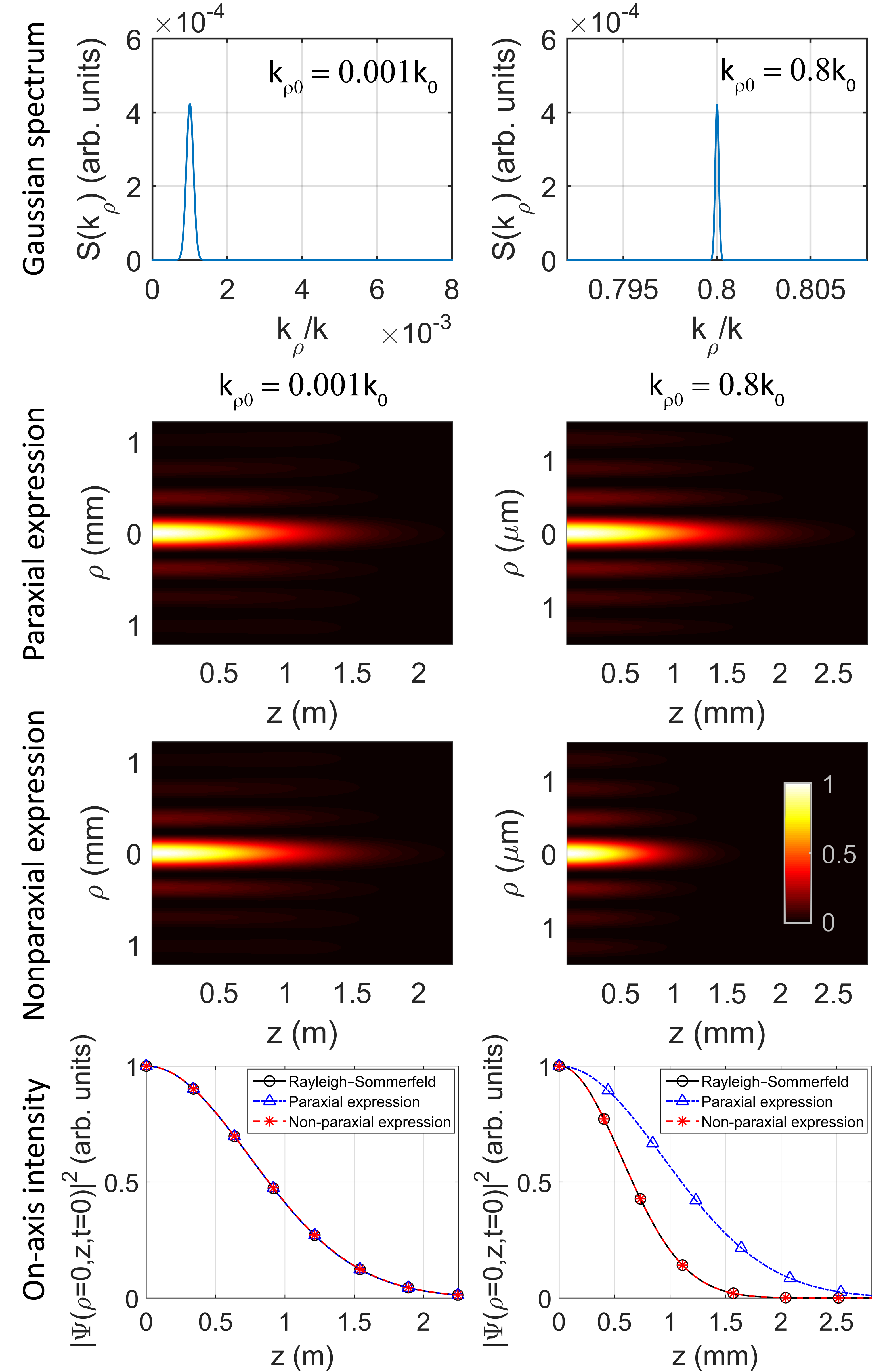
Fig. 7 contrasts Eq. (69) and Eq. (68) for two situations: paraxial () and highly nonparaxial (). In both cases, the medium is air, and . The first line of Fig. 7 depicts the Gaussian spectra, showing that they are very concentrated. The following two lines show the intensities predicted by the paraxial expression (Eq. (69), second line) and the generalized nonparaxial expression (Eq. (68), third line) 777Note that the intensities were normalized by their peak at .. It is clear that the two expressions agree in the paraxial regime, but in the nonparaxial case Eq. (69) overestimates the field depth predicted by Eq. (68). The last line shows the intensities at predicted by both expressions and compares them with the exact intensity calculated using the Rayleigh-Sommerfeld diffraction integral for the initial pattern . The three results coincide for the paraxial regime, but only Eq. (68) agrees with the diffraction integral for the nonparaxial situation. According to Eq. (67), the estimated field depths are and for the paraxial and nonparaxial examples, respectively, which accurately match the diffraction integral results.
10.2 Circular Parabolic-Gaussian (CPG) beam
If we apply the nonparaxial version of the envelope in Eq. (39) to Eq. (62), we get an azimuthally symmetric version of the PG beams, which we will refer to as Circular Parabolic-Gaussian (CPG) beams.
To illustrate, we will consider two examples. The first is an odd beam () with and while the second is an even beam () with , and . Both are analyzed in two regimes: paraxial () and nonparaxial (), with .
Since the envelopes of PG beams have definite parity in at , the initial patterns of CPG beams are Gaussian-apodized parabolic cylinder functions with an additional decay factor modulated by a fast oscillating sinusoidal pattern with period , as explained in sec. 9.3. Fig. 8 shows the initial patterns of the CPG beams for the paraxial case, in which . In the nonparaxial regime, the patterns are similar, but with much faster oscillations ().
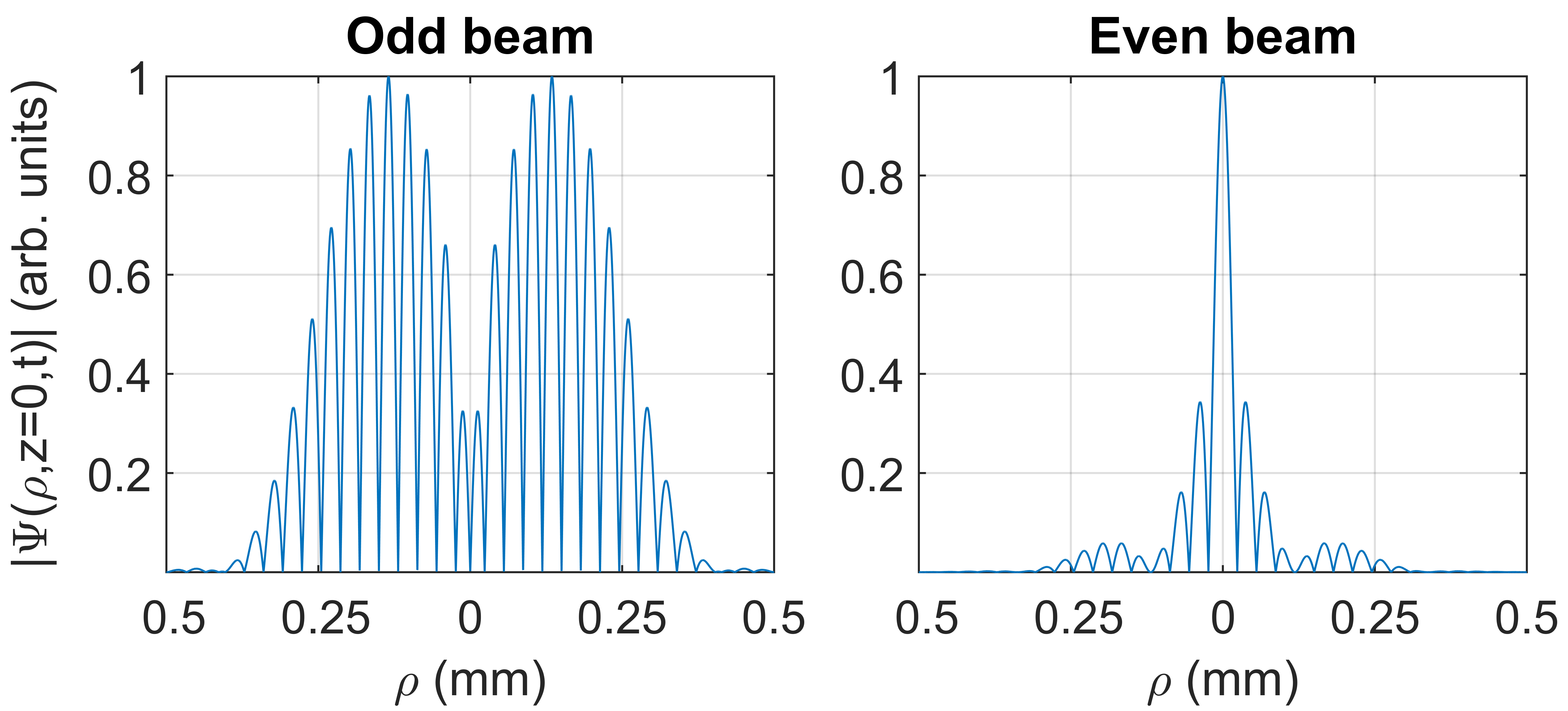
Fig. 9 presents the resulting spectra and the intensity profiles of the odd beam. The first line depicts the spectra, calculated from the inverse Fourier transform of the initial profile (analogously to Eq. (25)). Since the PG beams are solutions of the paraxial wave equation, their spectra are indeed concentrated and, in the case of their CPG counterparts, they are centered at . The second line shows the resulting intensity profiles, normalized by their peak intensities at . Although the odd symmetry makes the on-axis amplitude zero at , the sidelobes shown in Fig. 8 interfere constructively after some distance and create a very high-intensity peak over the axis, due to the concentration of the energy they carry in a small area. The effect is even more intense in the nonparaxial regime, in which the spot size is much smaller. The last line compares the on-axis intensity predicted by Eq. (65) and the numerical calculation of Rayleigh-Sommerfeld diffraction integral with the initial pattern given by Eq. (66). It is clear that in both paraxial and nonparaxial regimes the analytical expression is accurate.
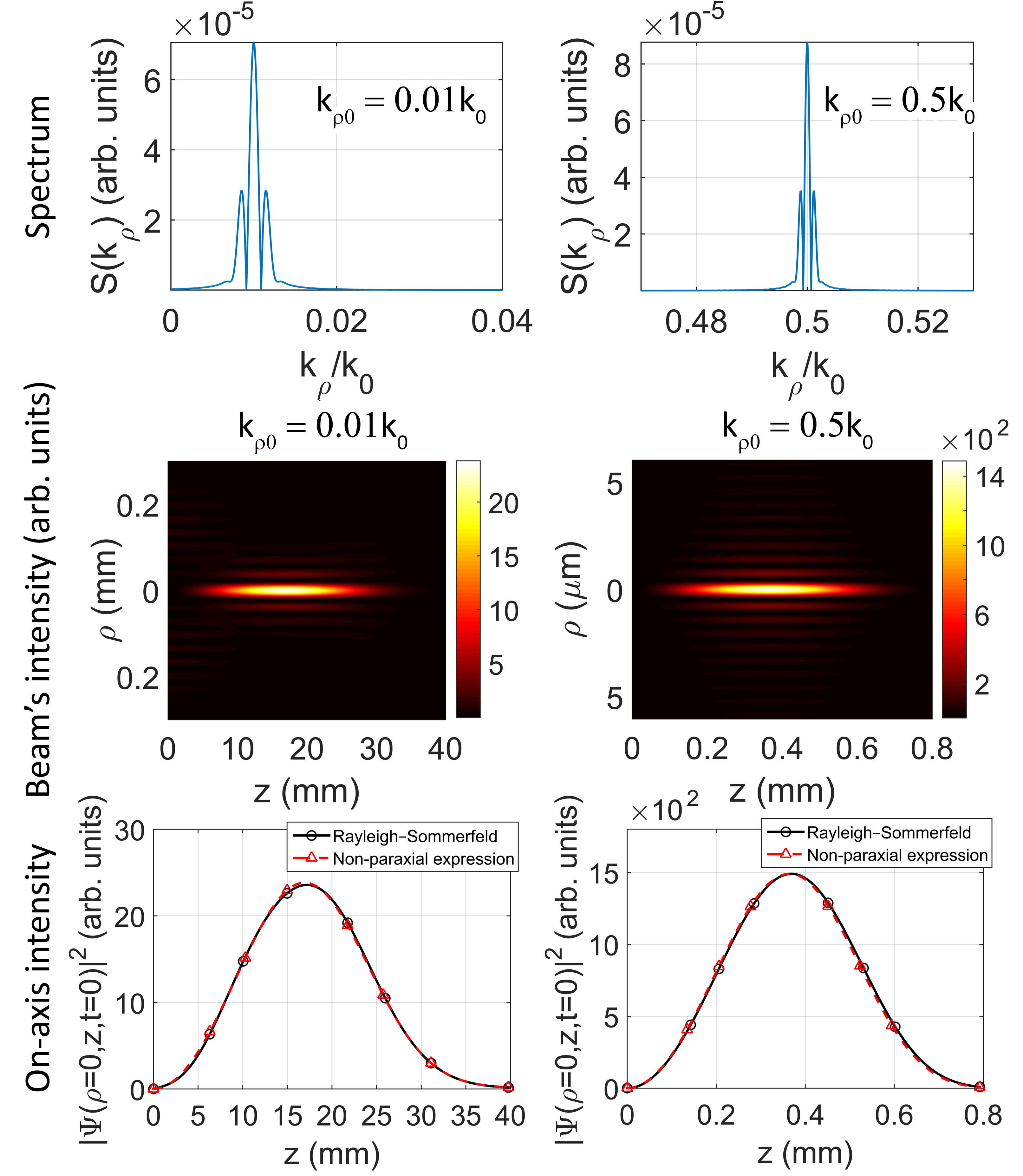
Fig. 10 presents the same kinds of results of Fig. 9 but for the even beam. We see again that the spectra are concentrated and that the on-axis intensities predicted by the analytical expressions are accurate. However, the even symmetry makes the peak intensities appear at . Therefore, due to the normalization, we do not see higher-intensity on-axis peaks as in Fig. 9.
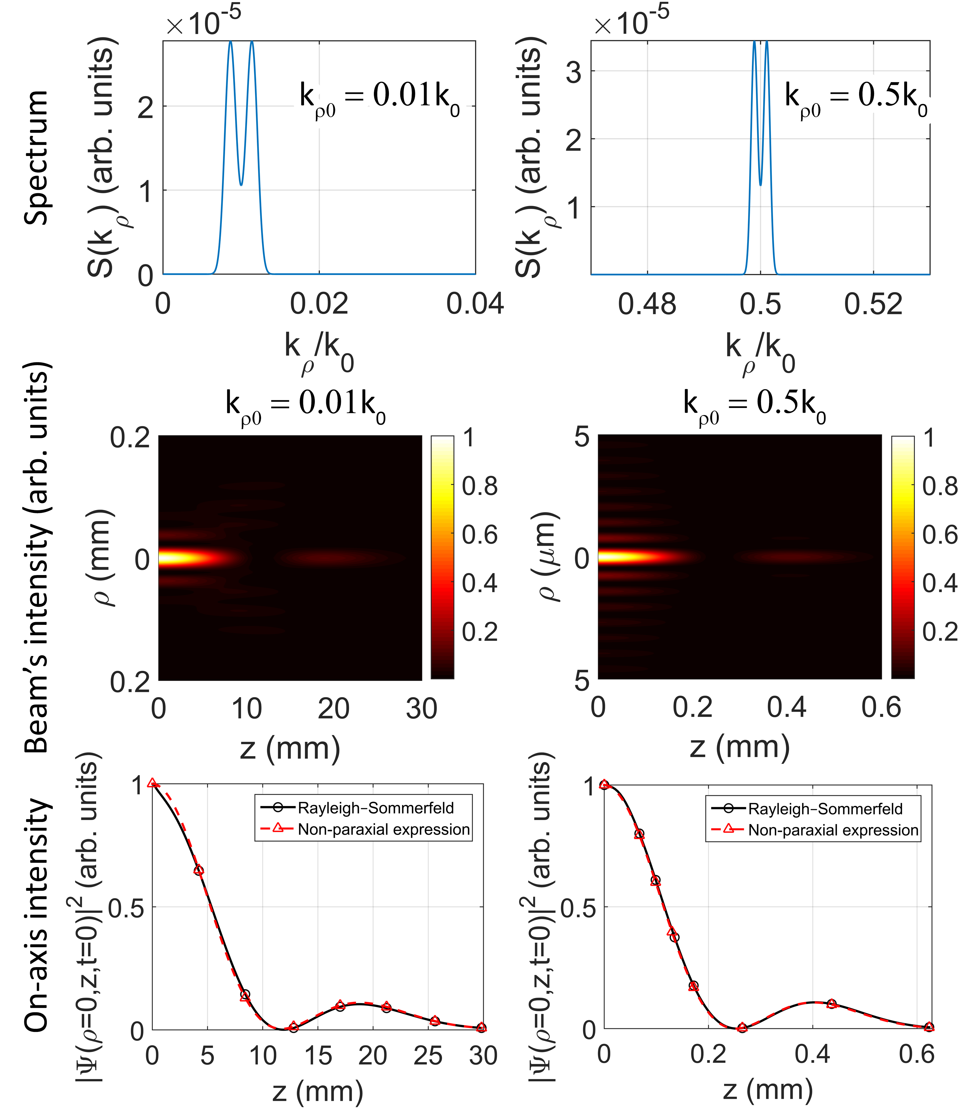
The field depths of the examples presented can be estimated by Eq. (67) without recurring to the plots of intensity profiles. We could use for a reasonable estimate, but better results are obtained by choosing based on the envelopes of Fig. 8. For the odd beam, embraces all its significant lobes, while the same happens for the even beam for . Using these values in Eq. (67), we get and for the odd beam under paraxial and nonparaxial regimes, respectively, while and for the even beam under paraxial and nonparaxial regimes, respectively.
11 Conclusions
In this work, we developed a theoretical analysis to efficiently describe the propagation of superpositions of waves with concentrated wavevector and frequency spectra, thus allowing a simple analytical description of fields with interesting transverse profiles. Starting with an extension of the paraxial formalism, we show how it can be applied to easily handle combinations of waves traveling in different directions without recurring to coordinate rotations. Moreover, and more importantly, we used a similar procedure to create a novel analytical description of azimuthally symmetric waves with concentrated spectra that can leverage all the previously presented results for unidimensional Cartesian waves, allowing us to build azimuthally symmetric versions of them and, therefore, to possibly derive new types of waves. Since these waves are composed of superpositions of zero-order Bessel beams with close cone angles that can be as large as desired, unlike in the paraxial formalism, we showed that it can also provide simple expressions for nonparaxial versions of known beams, such as the Bessel-Gauss beam. Finally, the validity and accuracy of the theory was corroborated by experimental demonstrations and comparisons to numerically-calculated Rayleigh-Sommerfeld diffraction integrals.
12 Funding information
São Paulo Research Foundation (FAPESP) (2015/26444-8); National Council for Scientific and Technological Development (CNPq) (304718/2016-5).
13 Acknowledgments
The authors thank Pedro Paulo Justino da Silva Arantes for his assistance with the numerical calculations of the diffraction integrals.
References
- [1] A. April. Bessel–gauss beams as rigorous solutions of the helmholtz equation. J. Opt. Soc. Am. A, 28(10):2100–2107, Oct 2011.
- [2] G. B. Arfken and H. J. Weber. Mathematical Methods for Physicists. Academic Press, 5 edition, 2001.
- [3] M. A. Bandres and J. C. Gutiérrez-Vega. Cartesian beams. Opt. Lett., 32(23):3459–3461, Dec 2007.
- [4] R. Borghi, M. Santarsiero, and M. A. Porras. Nonparaxial bessel–gauss beams. J. Opt. Soc. Am. A, 18(7):1618–1626, Jul 2001.
- [5] F. Gori, G. Guattari, and C. Padovani. Bessel-gauss beams. Optics Communications, 64(6):491 – 495, 1987.
- [6] I. S. Gradshteyn and I. M. Ryzhik. Table of Integrals, Series, and Products. Academic Press, 7 edition, 2007.
- [7] J. C. Gutiérrez-Vega and M. A. Bandres. Helmholtz–gauss waves. J. Opt. Soc. Am. A, 22(2):289–298, Feb 2005.
- [8] D. Lopez-Mago, M. A. Bandres, and J. C. Gutiérrez-Vega. Propagation characteristics of cartesian parabolic-gaussian beams, 2010.
- [9] R. L. G.-A. no and M. Zamboni-Rached. Superluminal, luminal, and subluminal nondiffracting pulses applied to free-space optical systems: theoretical description. Appl. Opt., 55(7):1786–1794, Mar 2016.
- [10] S. R. Seshadri. Virtual source for the bessel–gauss beam. Opt. Lett., 27(12):998–1000, Jun 2002.
- [11] O. Vallée and M. Soares. Airy Functions and Applications to Physics. Imperial College Press, 2004.