Hierarchy of critical temperatures
in four-layered
ferromagnet/superconductor nanostructures and control devices
Abstract
The four-layered F/S/F′/S′ nanostructure consisting of rather dirty superconducting (S) and ferromagnetic (F) metals is studied within the theory of the proximity effect taking detailed account of the boundary conditions. The F/S structures with four F and S layers are shown to have considerably richer physics than the F/S/F trilayer (due to the interplay between the 0 and phase superconductivity and the 0 and phase magnetism) and even the F/S superlattices. The extra phase superconducting states obtained for the four-layered F/S/F′/S′ system are found to be different from the known “superlattice” states. The dependence of the critical temperatures versus the F layers thicknesses is investigated. An optimal set of parameters is determined, for which the difference between the critical temperatures for different states becomes significant, and the corresponding phase diagrams are plotted. It is proven that this system can have different critical temperatures for different S and S′ layers. A conceptual scheme of a control device with superconducting and magnetic recording channels that can be controlled separately using a weak external magnetic field is proposed on the basis of the F/S/F′/S′ nanostructure. The devices with four, five, six, and seven different states are explored.
pacs:
74.78.Fk, 85.25.-j, 74.62.-c, 85.75.-dI Introduction
Superconductivity and ferromagnetism are antagonistic ordering phenomena and their coexistence in homogeneous materials requires special conditions that are hard to realize. One of possible explanation of the superconductivity suppression by ferromagnetic ordering in transition metals was given by Ginzburg (1956), who noted that the magnetic induction exceeds the critical field. This antagonism is also clear from the viewpoint of the microscopic theory: the attraction between electrons creates Cooper pairs in a singlet state, whereas the exchange interaction producing ferromagnetism tends to arrange electronic spins parallel to each other. Therefore, when the Zeeman energy of the electrons of a Cooper pair in the exchange field exceeds the coupling energy, the measure of which is the superconducting gap , the superconducting state is destroyed. In contrast to critical field acting on orbital states of the electrons of a pair, the exchange field acts on electronic spins (spin degrees of freedom), therefore the destruction of superconductivity due to this field is called the paramagnetic effect Chandrasekhar (1962); Clogston (1962).
However, the above mentioned coexistence of superconducting and ferromagnetic order parameters is easily achievable in fabricated or natural F/S heterostructures consisting of alternating ferromagnetic metal (F) and superconducting (S) layers. In this case superconducting and ferromagnetic electronic systems are spatially separated. Due to the proximity effect, the superconducting order parameter can be induced in the F layer; on the other hand, the neighboring pair of the F layers can interact with each other via the S layer. Such systems exhibit rich physics, which can be controlled by varying the thicknesses of the F and S layers, or by placing the F/S structure in an external magnetic field.
The modern technologies of production of the layered structures, such as molecular-beam epitaxy, allow to deposit layers of atomic thickness and to study the properties of such heterogeneous F/S systems as a function of the ferromagnetic () or superconducting () layer thickness. Numerous experiments on the F/S structures (contacts, trilayers, and superlattices) have revealed nontrivial dependences of the superconducting transition temperature on the thickness of the ferromagnetic layer (see the reviews Izyumov et al. (2002); Ryasanov et al. (2004); Buzdin (2005) and references therein).
The boundary value problem for the pair amplitude (the Cooper pair wave function) in a dirty superconductor for the F/S superlattice was formulated in pioneering works by Radović et al. (1991); Buzdin et al. (1992). The critical temperature that was also calculated as the function in Refs. Radović et al., 1991; Buzdin et al., 1992 exhibited both monotonic and nonmonotonic dependences. Oscillations of were related to periodical switching of the ground superconducting state between the 0 and phases, so that the system chooses the state with higher transition temperature . In the phase state the superconducting order parameter in the neighboring S layers of the F/S superlattice have the opposite sign, contrary to the 0 phase state in which has same sign for all S layers. The experimental evidence of the superconducting state in the F/S systems has been discussed in the review Ryasanov et al. (2004). The concept of a junction was proposed by Bulaevskii et al. (1977).
However, the boundary conditions used in Refs. Radović et al., 1991; Buzdin et al., 1992 are correct only in the limit of high transparency of the F/S interface. In subsequent studies Khusainov and Proshin (1997); Proshin and Khusainov (1997, 1998); Aarts et al. (1997) the boundary conditions have been derived from the microscopic theory, and they are valid for arbitrary transparency of the F/S interface. The solution of the boundary value problem Khusainov and Proshin (1997); Proshin and Khusainov (1997, 1998); Aarts et al. (1997); Tagirov (1998); Fominov et al. (2001, 2002); Bagrets et al. (2003) has revealed an additional mechanism of nonmonotonic dependence of due to modulation of the pair amplitude flux from the S layer to the F layer. This modulation is caused by the change of the FM layer thickness . Moreover, it has also resulted in a prediction of different types of behavior such as reentrant Khusainov and Proshin (1997); Proshin and Khusainov (1997, 1998); Izyumov et al. (2000) and periodically reentrant superconductivity Khusainov and Proshin (1997); Proshin and Khusainov (1997, 1998). Note that both the oscillations and the reentrant behavior of can appear not only in the F/S superlattice but also in simple F/S bilayer and F/S/F trilayer systems in which the phase superconductivity is impossible in principle! The reentrant character of superconductivity that we have predicted has been recently observed experimentally in the Fe/V/Fe trilayer Garifullin et al. (2002).
Now it may be considered as proven Izyumov et al. (2002) that superconductivity in the layered F/S systems is a combination of the BCS pairing with a zero total momentum of the pairs in the S layers and the pairing due to the Larkin-Ovchinnikov-Fulde-Ferrell (LOFF) mechanism Larkin and Ovchinnikov (1964); Fulde and Ferrell (1964) with a nonzero three-dimensional (3D) momentum of the pairs in the F layer. The LOFF pairs momentum is determined by the Fermi surface splitting caused by the internal exchange field (where is the Fermi velocity in the F layers). Usually it is assumed Radović et al. (1991); Buzdin et al. (1992); Demler et al. (1997); Proshin and Khusainov (1998, 1997); Khusainov and Proshin (1997); Aarts et al. (1997); Fominov et al. (2001, 2002); Bagrets et al. (2003); Tagirov (1998) that the momentum of the LOFF pairs is directed across the F/S interface (the so-called one-dimensional (1D) case). In our recent papers Izyumov et al. (2000, 2002); Khusainov and Proshin (2003) we took into account the spatial variations of the pair amplitude not only across the F/S nanostructure but also along the F/S boundary (the 3D case). In the general case, this leads to the increase of the critical temperature and to the smoothing of the oscillations, in comparison with the 1D version of the theory, due to the 3D-1D-3D phase transitions. The appearance of the 3D-1D-3D phase transition cascade is associated with the umklapp processes at which the LOFF pairs momentum is exactly conserved up to a minimal reciprocal lattice vector of the 2D surface LOFF states. Therefore is actually a quasimomentum and this fact is reflected in the revised F/S boundary conditions Izyumov et al. (2002); Khusainov and Proshin (2003). The use of the latter in turn can result in a dependence with one local minimum, which is a typical experimental nonmonotonic behavior Izyumov et al. (2002).
Of special interest is the study of the multilayered F/S structures, in which various types of magnetic order can arise in the F layers due to their indirect interaction via the S layers. Recently the theory of the proximity effect has been developed for the F/S structures taking into account the inverse influence of superconductivity on magnetism of the F layers and on mutual orientation of their magnetizations. This aspect of the proximity effect has been studied for the F/S/F trilayer “spin-switch” Buzdin et al. (1999); Tagirov (1999) and exploring the possibility of the cryptoferromagnetic state in the F/S bilayer Bergeret et al. (2000, 2004). The long-range proximity effect due to triplet superconductivity that arises in the case of non-collinear alignment of magnetizations in the F layers has been studied for the F/S/F trilayer system in Refs. Bergeret et al., 2001, 2003; Volkov et al., 2003; Fominov et al., 2003.
An interplay between the 0 and phase types of superconductivity in the S layers should be included in the above-mentioned magnetic mutual accommodation in the F/S superlattices. This added competition leads to two layered antiferromagnetic superconducting (AFMS) states Izyumov et al. (2002); Khusainov et al. (2001); Proshin et al. (2001). In the AFMS state the phases of the magnetic order parameter in the neighboring F layers are shifted by , i.e. the exchange fields have opposite signs in the neighboring F layers. This state with antiparallel alignment of the corresponding magnetizations may be considered as a manifestation of the phase magnetism. Similar to the F/S/F trilayer Buzdin et al. (1999); Tagirov (1999), in the case of the F/S superlattice the AFM ordering of the magnetizations of all F layers leads to the significant reduce of the pair-breaking effect of the exchange field for the S layers, and to the raise of the critical temperature of the layered system. This theoretical prediction has been experimentally confirmed for the Gd/La superlattices Goff et al. (2002). Goff et al. (2002) have observed that the superlattices with prepared antiferromagnetic ordering of the magnetizations in the adjacent Gd layers undergo the transition into a superconducting state at considerably higher temperatures in comparison with the superlattices with ferromagnetic ordering of the Gd layers. This mutual accommodation between the superconducting and magnetic order parameters reflects a quantum coupling between the boundaries. The competition between the 0 and phase superconductivity and the 0 and phase magnetism leads to a change in the classification of the F/S superlattice state Khusainov et al. (2001); Proshin et al. (2001); Izyumov et al. (2002).
The F/S nanostructures possess two data-recording channels: the superconducting one determined by conducting properties of the S layers, and the magnetic one determined by ordering of the F layer magnetizations. The F/S/F trilayer devices, proposed in Refs. Buzdin et al., 1999; Tagirov, 1999; Oh et al., 1997, operate through transitions between the superconducting (S) and normal (N) states that are induced by changes of the mutual ordering of the magnetizations of the adjacent FM layers. These changes are controlled by an external magnetic field . The data stored in the superconducting and magnetic channels of this switch device change simultaneously, and the magnetic order completely determines the “superconducting information”. The scheme of a complex device on the basis of the F/S superlattices, in which the superconducting and magnetic data-recording channels can be controlled separately, has been proposed in Refs. Khusainov et al., 2001; Proshin et al., 2001.
In Section II we briefly discuss the earlier proposed control devices (“spin switches”) based on the F/S nanostructures. In Section III we explore the four-layered F/S/F′/S′ system (see Fig. 1) assuming the competition between the 0 and phase magnetism and the 0 and phase superconductivity takes place. We solve the Usadel equations for this structure taking into account the boundary conditions. In Section IV we construct the phase diagrams with an optimal set of parameters. In Section V we propose a scheme of a control device based on the studied F/S/F′/S′ system and discuss its few possible operating regimes.
II Spin switches for current on the basis of F/S heterostuctures
A conceptual scheme of a spin switch device for current based on a F/S/F trilayer was proposed by Buzdin et al. (1999) and Tagirov (1999) for the case of the “Cooper limit” when the thicknesses and of the S and F layers are much less than the corresponding coherence lengths and , respectively. It has been theoretically shown, that the “antiferromagnetic” (AFM) configuration of such a three-layered system with an antiparallel arrangement of the magnetizations of the F layers has a higher transition temperature in comparison with the one for the “ferromagnetic” (FM) configuration. In other words the AFM configuration is energetically more favorable and the AFMS state is the ground state of this system at in the absence of an external magnetic field. The nature of this behavior of is related to a reduction of the pair-breaking action of the exchange field of the F layers in the AFM configuration on superconducting pairs, i.e. to a partial compensation of the paramagnetic effect.
Applying small magnetic field higher than the coercivity of the F layer one can change the AFM orientation of the magnetizations to the FM one. Under certain conditions the trilayer system can undergo a transition from a superconducting (AFMS) state to a normal (FMN) one, i.e. from a state with zero resistance to a resistive one. As the magnetic field is turned off, the AFM orientation of the magnetizations (the phase magnetic state) and the superconducting properties of the system are restored. Note that in a certain sense the F/S/F switch operates in the same manner as an usual isolated superconductor which turns into the normal state if the applied field exceeds the critical field . Moreover, since the value of the critical field is determined by the difference between the critical temperature and the temperature of a sample , the can be made arbitrary small by choosing the temperature close enough to the critical temperature.
Considering the switches for current it is necessary to note a few earlier papers Clinton and Johnson (1997); Oh et al. (1997) on similar devices with one channel of data recording that operate on the basis of transition between superconducting and normal states. A model of a superconducting switch device has been proposed in Ref. Clinton and Johnson, 1997 on the basis of the F/I/S structure (I is an insulator) in which the magnetic fringe field of a ferromagnetic film arising due to special switch geometry is used to control the critical current in an underlying superconducting film.
The switch device on the basis of three-layered F′/F′′/S structure in which the direction of the magnetization in the relatively thin internal F′′ layer is changed by a weak magnetic field was theoretically studied in Ref. Oh et al., 1997. As the mutual ordering of the magnetizations and changes from an antiparallel arrangement to a parallel one, the device undergoes a transition from the S state to the N one.
We would like also to note that an experimental attempt was made to observe the “spin switch” effect in the three-layered CuNi/Nb/CuNi system Gu et al. (2002). Authors succeeded in showing that the critical transition temperature is higher for the AFMS state than it is for the FMS state. However, due to a non-optimal choice of parameters of the system the measured difference between and did not exceed 0.005 K. Despite this small difference the experimental setup allows to clearly identify the two states.
The multilayered F/S systems in which there is an additional competition between the 0 and phase types of superconductivity have much greater potential in fundamental studies and future device applications. In fact, in the F/S superlattices the pair amplitude should satisfy to periodical conditions , where is the superlattice period, and and are the phases of superconducting and magnetic order parameters, respectively. As it follows from the detailed analysis carried out in works Izyumov et al. (2002); Khusainov et al. (2001); Proshin et al. (2001, 2002) on the basis of the theory of the proximity effect Khusainov and Proshin (1997); Proshin and Khusainov (1997, 1998); Izyumov et al. (2000) for the case of a contact between the dirty S and F metals, the superconducting states of the F/S superlattice can be described using four different sets : 00, 0, 0, and . This leads to a considerably greater number of combinations of the magnetic (FM or AFM) and conducting (S or N) properties of the F/S superlattices (up to five different ones) in comparison with the trilayer case, in which only two states (AFMS and FMN) have been considered Tagirov (1999); Buzdin et al. (1999). Hence, there is a much larger variety of regimes at which the control devices on the basis of the F/S superlattice can operate. The conditions of the separate control of the magnetic and superconducting channels of data recording were determined. Note that the critical thickness of the S layers , at which vanishes, is always less for the AFMS state than for the FMS state. More recently, Fominov et al. (2003) have shown for the F/S/F trilayer that superconductivity has merely the AFMS nature at any thickness .
Thus, as we can see, the F/S superlattices possess a number of theoretical advantages in comparison with the three-layered structures, that make them a better choice for a development of a conceptual scheme of the proposed control devices to be used for data storage and processing. However, from a practical point of view in case of the superlattices it is quite difficult to control orientation of the magnetization separately of each F layer by an external magnetic field 111 The control of ordering of all magnetizations results in the need of using additional sequences of the switching-off fields that return the system to its initial state if the localized spins ordering in each F layer is not of an “easy-plane” type.. The simplest F/S system that assumes a competition between the 0 and phase states both in magnetism and superconductivity is a four-layered F/S/F′/S′ system with two superconducting layers and two ferromagnetic layers that differ in their boundary conditions for the inner and outer layers in contrast to the F/S superlattice approach Izyumov et al. (2002); Proshin et al. (2002), where the four-layered F/S/F/S system was considered only as an elementary cell with periodic boundary condition.
III Four-layered F/S/F′/S′ structure
Consider the four-layered F/S/F′/S′ system with alternating layers along the axis (see Fig. 1). Assume that both outer F and S′ layers have thicknesses which are half the thicknesses of the corresponding inner F′ and S layers, /2 and /2, respectively. This would allow us to simplify the solutions, and, thereafter, to compare the obtained results for the four-layered structure with the ones for the trilayer and superlattice cases.
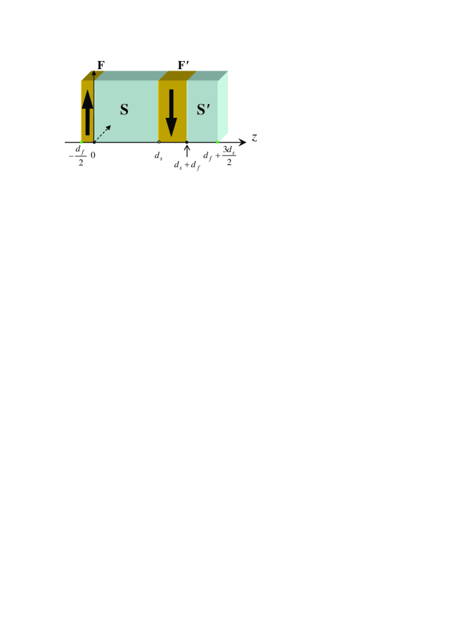
The choice of this particular system allows one to take into account a possible phase change of the superconducting and magnetic order parameters while traversing through the F or S layers, and to investigate mutual accommodation of the competing BCS and LOFF types of electron pairing on the one hand, and of superconductivity and magnetism on the other. For simplicity we will use the 1D model when both order parameters and the pair amplitude depend only on . An extension of the results to the 3D case is straightforward (see, for example, Refs. Izyumov et al., 2002 and Khusainov and Proshin, 2003). We note here that the distinction between solutions obtained within the framework of the 1D and 3D models is marginal for the choice of parameters studied below Khusainov et al. (2001); Proshin et al. (2001).
To find the critical temperature we assume the usual relation between the energy parameters of the system , where is the Fermi energy and is the critical temperature of the S material. We also suppose the dirty limit conditions
Here is the mean free path length for the S(F) layer; is the Fermi velocity; is the superconducting coherence length; is the spin stiffness length; is the BCS coherence length; is the diffusion coefficient.
In this case, the common boundary value problem Proshin and Khusainov (1998) for each layer is reduced to the Gor’kov self-consistency equations for the “pair amplitudes” 222Usually the term “pair amplitude” is used for . The latter in turn is proportional to the sum of Gor’kov function over Matsubara frequency . However, in this paper we often use this term for due to traditions Izyumov et al. (2002) and for simplicity.
| (1) |
and to the Usadel equations, that appear for the S and F layers as follows
| (2) |
In Eqs. (1),(2) is the Matsubara frequency; and are the superconducting order parameter and the electron-electron coupling constant in the S(F) layers, respectively. The prime on the summation sign indicates cutoff at the Debye frequency . The diffusion coefficient in the F layer is assumed to be real rather than complex Izyumov et al. (2002) since the difference between its two values is insignificant under the conditions used below (see discussion in Ref. Khusainov and Proshin, 2003).
The coupling between the superconducting and ferromagnetic layers is provided by corresponding boundary conditions, which connect the pair amplitude fluxes with the pair amplitude jumps on the interfaces of the layers, and are written in the following form Khusainov and Proshin (1997); Proshin and Khusainov (1997, 1998)
| (3a) | |||
| Here index numbers the interfaces, and takes the following values: , , . The upper signs are chosen at , the lower ones are chosen at . The pair amplitude flux through the outside boundaries (, ) is absent | |||
| (3b) | |||
The last conditions (3b) distinguish the F/S/F′/S′ case from the F/S superlattice case Izyumov et al. (2002); Proshin et al. (2002) in which the periodical boundary conditions are imposed. In Eq. (3a) is the boundary transparency at the S(F) side () Izyumov et al. (2002); Proshin and Khusainov (1998). They satisfy the detailed balance condition: , where is the density of states at the Fermi level.
In order to calculate the critical temperatures of this F/S system taking into consideration the boundary transparencies, thicknesses of layers, etc. we should solve the system of equations (2) and (3) together with the self-consistency equations (1).
The powerful pair-breaking action of the exchange field () is the basic mechanism for the destruction of superconductivity in the F/S systems. For simplicity Proshin and Khusainov (1998) assume that () in the F layers. We will search the solutions of equations (1)-(3) for the inner layers as a linear combination of symmetric and antisymmetric functions relative to the centers of the S and F′ layers. The pair amplitudes look the same as in the superlattice case Proshin et al. (2001). The zero flux of the pair amplitude through the outside boundaries (3b) determines only the even cosine-like functions for the outer layers. At these boundaries the antinodes should be fixed. Thus the simplest solutions of the boundary value problem for the F/S/F′/S′ system have the following form
| (4a) | |||||
| (4b) | |||||
| (4c) | |||||
| (4d) | |||||
Here and are the components of the wave vector that describe spatial changes of the pair amplitudes and across the layers (along the axis) independently of the frequency . The chosen form of the and pair amplitudes is related to the symmetry of F/S/F′/S′ system. In Eqs. (4b) and (4c) the first terms are responsible for the symmetric superconducting 0 phase solutions, while the second terms are responsible for the appearance of superconducting antisymmetric phase solutions (see below discussion in Sec. IV).
Since we are mainly interested in performing qualitative studies of the properties of the F/S/F′/S′ nanostructure, the single-mode approximation (4) is used to obtain the analytical solution of the complicated boundary value problem. However, when quantitative estimates are needed (to fit theoretical results to experimental data) the latter approximation works well only for a certain range of the values of the parameters in the problem Fominov et al. (2001, 2002). According to our estimates Proshin and Khusainov (1998) the optimal set of parameters used below is close to this range (). Note that in any approximation (single-mode, multi-mode, etc Fominov et al. (2002)) the symmetry of the problem solutions will be different for the different S and S′ (F and F′) layers. This fact reflects the general property of the studied system: the nonequivalence of layers of the same type, which results in different superconducting properties of the internal S and outer S′ layers.
Substituting the solutions (4) into the self-consistency equations (1) and performing the standard summation over we derive the usual Abrikosov-Gor’kov type equation for the reduced superconducting transition temperatures of the S and S′ layers, respectively
| (5) |
where ; is the digamma function, and the pair-breaking parameter is the solution of the other transcendental equation (see Eqs. (10)-(11), and (7) below), which may differ not only for each of the possible phases, but also for each superconducting layer (S and S′) as well. To get an equation for it is necessary to exchange for and for in Eq. 5 (see also Eq. (7) and its discussion below).
Substituting (4) in (3) we obtain a set of 6 equations for factors , , , , ,
| (6) |
where following notations are introduced
| (7) |
Quantities related to the outer superconducting S′ layer () or the inner F′ layer (, ) are marked with a prime. The prime also appears at corresponding wave vectors ( or ) on the right side of the expressions (7). In the framework of the made approximations the complex value of the wave vectors is defined as follows
| (8a) | |||||
| (8b) | |||||
The equations (8a) are valid for the case of the mutual ferromagnetic ordering of the magnetizations in the F and F′ layers, and the equations (8b) are valid for the case of the antiferromagnetic ordering when , , i.e. the phase of the magnetic order parameter equals .
Note that within the 3D model Khusainov and Proshin (2003); Izyumov et al. (2002, 2000) and in Eqs. 8 should be replaced by and , respectively. Here is a wave vector in the F/S boundary plane, which is responsible for the 2D interface LOFF states with the spatial oscillations of the pair amplitude in the plane. The concrete value of is found from the condition for maximum of . However, in our case the difference between the 1D () and 3D () approaches is unessential for the selected set of the system parameters (see Section IV below).
Thus, the expressions obtained above include a competition between the 0 phase and the phase types of superconductivity. They also take into account interaction of the localized moments of layers F and F′ through the superconducting layer S. The quantum coupling both between the adjacent S and S′ layers through the F′ layer and between the adjacent F and F′ layers through the S layer is provided by superconducting correlations of conduction electrons. It is known de Gennes (1964) that the role of the true superconducting order parameter for the heterogeneous systems discussed in the paper is played by a pair amplitude . In contrast to a parameter , the pair amplitude does not vanish in the ferromagnetic layer, but provides a quantum coupling between the layers via superconducting correlations which have an inhomogeneous oscillatory behavior due to the LOFF-like type of pairing.
The pair-breaking parameters for the S layer and for the S′ layer should be determined from the condition of nontrivial compatibility of the set of equations (6). It is possible to factorize the corresponding determinant and to obtain the following equation
| (9) |
Equation (9) can be simplified by taking into account the independence of the solutions for the S and S′ layers and knowing the solutions for the superlattice case. It is possible to obtain the following sets of equations for and , which are different for the FM and AFM configurations. Note that only equations leading to the finite nonzero critical temperature are kept in these sets (see Eqs. (10) and (11) below).
For the FM ordering of the magnetizations we obtain two cases FM() and FM()
| (10) |
Here and for the F′ layer are substituted by and , respectively, due to Eq. (8a).
According to equation (8b), when (leading to and ), for the AFM ordering we have two other cases AFM() and AFM()
| (11) |
In the general case, there are 4 different solution sets FM(), FM(), AFM(), and AFM() for the S and S′ layers, each of which completely defines the state of both layers and, hence, the corresponding reduced transition temperatures and (5). However, since the solution of Eq. (5) does not change when is replaced by its complex conjugate the solutions for the S′ layer do not depend on relative orientation of the magnetizations: the solution of Eq. (5) for the FM() case coincides with the solution for the AFM() case. The same is true for the solutions for the FM() and AFM() cases.
Moreover, two different solutions for the outer S′ layer (FM()AFM() and FM()AFM()) always coincide with the solutions for the F/S superlattice Izyumov et al. (2002); Khusainov et al. (2001); Proshin et al. (2001), in which an orientation of the magnetizations is common to all F layers (the FM case). We try to classify the solutions (10),(11) for the F/S/F′/S′ system following the classification scheme proposed for a superlattice in Refs. Izyumov et al., 2002; Khusainov et al., 2001; Proshin et al., 2001 (see also Section II). As it follows from that classification there are four possible states for a superlattice, which are described using two possible values (0 and ) for the phases of the superconducting and magnetic order parameters. Two pairs of equations for the in the S′ layer that coincide FM()=AFM() and FM()=AFM() lead to the 00 and solutions, respectively: the first symbol corresponds to the superconducting order parameter phase (), the latter one corresponds to the magnetic order parameter phase (). Thus, we have only two distinguishable solutions and for the S′ layer (see below Fig. 2a,b).
The latter can be easily understood from the physical point of view. Only one ferromagnetic layer (F′) acts on the outer S′ layer. As a result the state of the layer depends only on the magnitude of the exchange field in the F′ layer and does not depend neither on its sign nor on mutual ordering of the magnetizations. In other words, the S′ layer is always in the local ferromagnet (FM) environment, therefore the magnetic solutions do not exist for this layer.
For the S layer we have also two known superlattices solutions, namely, the FM() solution, that leads to the 00 solution, and the AFM() solution, that leads to the solution (the 0 phase superconductivity and the phase magnetism). Finally, there are two extra solutions FM() and AFM(). Their presence is related to the external boundary conditions (3b) since the pair amplitudes (4a), (4d) contain only even cosine solutions. These states are the superconducting states, and in order to distinguish them from the earlier mentioned superlattice solutions we will denote these ones with tilde ( is the phase of the magnetic order parameter). Thus the FM() solution determines the state of the four-layered system and the AFM() solution corresponds to the one.
IV Discussion of the phase diagrams
Taking into account the notations of Eq. (7) the sets of Eqs. (5),(8)-(11) can be used to study the dependence of critical temperatures ( and ) of the four-layered F/S/F′/S′ system on the reduced thicknesses of the superconducting and magnetic layers, and .
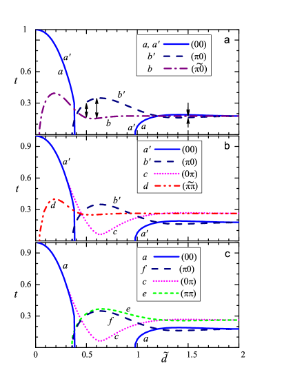
(a) – the phase diagram of the four-layered system for the ferromagnetic (FM) configuration of the magnetizations of both F layers. The arrows show the difference between the states which are discussed in the paper.
(b) – the phase diagram of the four-layered system for the AFM configurations.
(c) – the phase diagram of the F/S superlattice where the thicknesses of all F layers equal , and the thicknesses of all S layers equal . In this case all S layers have the same critical temperature. That is why only the curves are shown here. The and curves form the phase diagram for the F/S/F trilayer in which the thicknesses of both F layers are equal to .
There are four more theoretical parameters of the system (), that are necessary to consider in a general case. Keeping in mind a possibility of an application of the system as a “control device” we have searched for such a set of parameters for which the difference between the various states of the F/S/F′/S′ system is sufficiently large to be observed. After performing numerous computer experiments we have found a range for the values of the parameters that satisfies these conditions. The optimal range of parameters should be as follows: the boundary should be sufficiently transparent (), the ferromagnetic metal should be sufficiently dirty or (and) weak enough in regard to its magnetic properties (), and the parameter . From experimental viewpoint this constraint on the values of the parameters does not look unreasonable. Note, the stronger is an implementation of each inequality, the larger can be a difference between critical temperatures for the 0 and magnetic states. The choice of any one of these parameters lying out-of-range leads to significant decreasing that difference. Parameters and should satisfy to the “dirty limit” conditions. Their influence on the noted above difference is minimal. Though all values are important for a shape of the dependence (this has been detailed in the recent review Izyumov et al. (2002)).
A set of phase curves and for the optimal values of the parameters is shown in Fig. 2. The notation used for the curves corresponds to the notation used in Eqs. (10),(11). The curves and are not shown in Fig. 2 since and .
As one might expect, the and curves for the S′ layer in Figs. 2a and 2b are identical for both FM and AFM configurations, and the curve for the S′ layer coincides completely with the curve for the S layer since both of them describe the same 00 state according to the superlattice classification scheme Khusainov et al. (2001); Proshin et al. (2001); Izyumov et al. (2002). The rest of the states for the inner S layer (the curve for the FM configuration, and the and curves for the AFM one) have different dependencies as compared with the ones for the S′ layer and each other.
The phase diagram for the F/S superlattice (Fig. 2c) is obtained following procedures developed in Refs. Izyumov et al., 2002; Khusainov et al., 2001; Proshin et al., 2001. Contrary to the four-layered F/S/F′/S′ system in the superlattice case the different S layers have the same critical temperatures due to the periodicity condition imposed on the pair amplitudes. The , , and curves for the F/S superlattice completely coincide with the , , and ones for the four-layered system, respectively. The superlattice state (the curve), which is not found for our four-layered system, can be obtained from Eq. (5) where corresponding parameter is determined by following equation
To obtain the phase diagram for the F/S/F trilayer we have to exclude the states with the phase superconductivity (the and curves) from this figure. Hence as it follows from Fig. 2 and discussions presented here the four-layered system has more physically different states than the F/S/F trilayer and even the F/S superlattice!
Thus, the , , and states of the four-layered system (Figs. 2a,b) correspond to the same states of the superlattice (Fig. 2c). The state (the curve in Fig. 2a) and the one (the curve in Fig. 2b) are the states associated with the phase superconductivity. These are two extra solutions which are not found in the superlattice case (Fig. 2c). The main difference between these and the known states is the peak position. For the inner S layer it is shifted to the lower values of the thickness compared with the superlattice case due to the implementation of the external boundary conditions (3b).
The above-mentioned peculiarities of the four-layered system lead to different critical temperatures of different S layers. To show this consider the FM configuration (Fig. 2a) in detail. If there is no difference between and for the 00 state then the case of the phase superconductivity is more interesting since there is a difference between and . Actually for each superconducting layer the upper envelope curve is realized due to free energy minimum condition. In the case of the FM configuration that will be curve and one for the S′ and S layers, respectively. This leads to switching the ground state between the states with the 0 and superconducting phases as the thickness changes (at and , respectively).
In the phase superconductivity case, the order parameter has opposite signs for the S and S′ layers. Accordingly, the pair amplitude in the inner F′ layer (Eq. 4c) has a sine-like behavior () and is antisymmetric with respect to the layer center at which the sign change of the pair amplitude takes place while traversing the F′ layer. The above-mentioned different behavior in the S and S′ layers (the and curves in Fig. 2a, respectively) leads to a difference between critical temperatures and . For instance, at the reduced critical temperature of the S layer is equal to 0.177, and , at the difference is larger: and . If the reduced thickness were equal 0.6, the difference would be almost maximal: , and .
The reduced critical temperatures and that correspond to these three values of the reduced thickness are shown in Fig. 2a by arrows. The difference between two critical temperatures and should be observed in experiments with the special field-cooled samples prepared with the FM ordering of the magnetizations (see Ref. Goff et al., 2002 for experimental details).
The appearance of the critical temperature difference in the four-layered F/S system is a manifestation of the critical temperatures hierarchy in its clearest form. The origin of the difference is obvious because, firstly, the S and S′ layers are in different magnetic environment and, secondly, they have different boundary conditions. In particular it is expressed in the above mentioned shift of the peak of the dependence due to the outside boundary conditions.
For the AFM configuration of the F/S/F′/S′ system we have a similar picture (Fig. 2b), but in this case there are four different curves. Note that all above mentioned peculiarities take place as well. As it has been discussed above, the phase curves for the S′ layer are the same for both the FM and the AFM orientations. Two different solutions are obtained for the inner S layer. One of them is the known “superlattice” solution (curve ) while the second one is the solution (curve ). There is also a competition between the 0 and phase superconductivity that leads to a appearance of the corresponding envelope curves of the second order phase transition for the S and S′ layers ( and , respectively).
The solution corresponds to the and case, and the and factors are not equal 0, i.e. the pair amplitude in the S layer does not possess any parity. The admixture of the sine solutions to the cosine ones in expression (4b) reflects the partial compensation of the paramagnetic effect of exchange field for the S layer in the AFM state with antiparallel alignment of the F layers magnetizations. The previous statement applies to the state in the S′ layer too.
As in stated above FM case, the difference between and can be observed in experiments with the special field-cooled AFM samples.
Let us take up the common case, when there is the interplay of all the four states (10),(11), to clarify the winners in this competition. For convenience all the phase curves are shown in Figs. 2a,b in one combined diagram (Fig. 3).
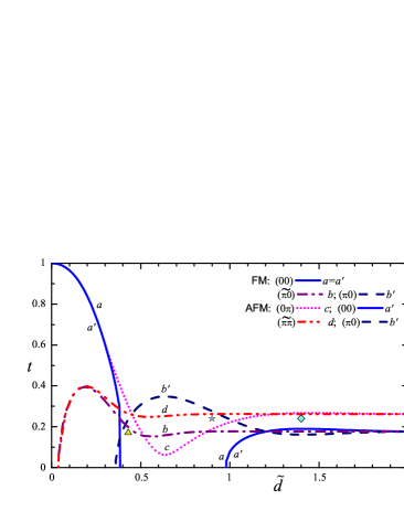
Note, that at the state (the curve in Fig. 2b and in Fig. 3) has the highest among all possible states for the S layer , but that is lower than the appropriate temperature for the state of the S′ layer . According to the theory of second-order phase transitions, the state possessing the lower free energy (higher is realized. Thus for the samples with the reduced thickness the S and S′ layers are both in the normal (N) state if the temperature . Below the S′ layer becomes superconducting (S) but the S layer remains in the N state while . Finally, at the AFMS state (AFM()) wins and for the whole system we have the case with the phase superconductivity and the phase magnetism.
At we have the following chain of the second order phase transitions: NN (or NN) SN SS (see a caption to Fig. 4 for an explanation of the notation). Thus at low temperatures the AFMS state (AFM()) wins too, but this state is associated with the 0 phase superconductivity. Note in the framework of our theory only transition temperatures can be found and it is not possible to determine what state inside the “normal” state region is preferable.
The analogous analysis can be carried out for the entire range of the reduced F layer thicknesses (). Assume the system can choose its own state according to the theory of the second order phase transitions. The state with higher critical temperature wins, and one of four states defined by Eqs. (10)-(11) (see also Figs. 2a,b and 3) is realized for the system. A complete phase diagram constructed for the system is presented in Fig. 4. Four different regions can be defined for this diagram: at high temperatures both S and S′ layers are in normal state and the mutual ordering of the magnetizations in the F and F′ layers is unimportant. As it follows from the phase diagram, there are two regions marked in dark grey color (magenta in color online version) with mixed antiferromagnetic state for which the inner S layer is superconducting (S), and the outer S′ one is normal (N). The striped light grey (yellow) marked region corresponds to the mixed state with the superconducting outer S′ layer and the normal S layer. Finally, at low temperatures and/or at small thicknesses the system is in the ground AFMS state (grey (blue) marked region).
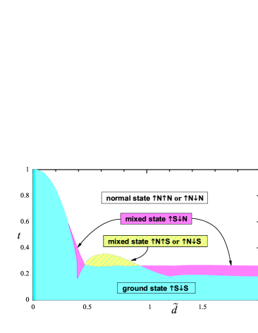
Thus, if the inner S layer is in the superconductive state then ordering of the magnetizations should be antiferromagnetic. This is the result of the inverse action of superconductivity on magnetism.
Note, the details of the phase diagram significantly depend on the choice of the system parameters and the above analysis was carried out assuming the absence of an external magnetic field ().
V Control device scheme
In this section we propose a conceptual scheme of a “control device” based on the four-layered F/S/F′/S′ structure.
Following the previous studies performed on spin valves Dieny et al. (1991); Tagirov (1999)and for technical convenience, we add to the left external layer of the system one extra layer of a magnetic insulator (MI), whose role is to pin the direction of the magnetization in the outer F layer. One of the possible consequences of that is the return of our system to the initial state (in a magnetic sense) after switching off the magnetic field. Otherwise it is necessary to use additional sequences of the switching-off fields4444footnotemark: 44 to achieve that. Note that it is more convenient to use the 4-layered system than the F/S superlattice Proshin et al. (2001); Khusainov et al. (2001); Izyumov et al. (2002) since it is easier to change the mutual ordering of the magnetizations of the F layers for this system. Thus, formally, our system becomes the MI/F/S/F′/S′ one. However this practically does not affect the preceding computations performed for the four-layered system, and we will use the notations earlier introduced for the four-layered system.
We can control the state of the F/S structure by applying a small external magnetic field , which slightly changes the phase diagram of the sample at the fixed temperature Buzdin et al. (1999); Tagirov (1999); Proshin et al. (2001); Khusainov et al. (2001). In this case there are specific values of the magnetic field: the coercivity at which the orientation of the magnetization in the F′ layer can be reversed, the critical field which destroys superconductivity, and the pinning field at which the direction of the pinned magnetization in the outer F layer can be reoriented. Assume that the ordering of localized spins in the F and F′ layers is of an uniaxial type and the magnitudes of these fields are related as follows 333By estimatesKittel (1975); Tagirov (1999); Rusanov et al. (2004) Oe. In the case of ferromagnets with the easy plane parallel to the F/S interface plane Oe. : .
The study of the combined phase diagram (Fig. 3) helps in optimizing the choice of parameters of the four-layered F/S/F′/S′ system, making it possible to control its superconducting and magnetic states. Assume the system is in one of the “working” points shown in the diagram. Each of these “working” points characterizes a sample that is described by a concrete set of parameters (, , , etc.), including the current temperature of a sample . At zero magnetic field the system is in the initial AFM state. By applying an external magnetic field, we can change the state of the system. The changes in the magnetic field lead to transitions of the system between these states. Note that the system in the shown points (, , ) can have a number of logically different states (up to 7 ones in the case).
Choose one of them, the “star”, which is located below the curves and in Fig. 3 (the reduced “working” temperature of the sample , ). The system in this point can have up to 6 different states. Changing first the external magnetic field applied in the direction of the pinning field, one can induce transitions of the system between the ground AFMS state, the mixed FM state, and the normal FM state. Applying the external magnetic field in the opposite direction one can induce three other transitions between the ground AFMS state, the mixed AFM state, the antiferromagnetic normal (AFMN) state, and, finally, the ferromagnetic normal (FMN) one.
To show this in more detail, we assume that the orientation of the magnetization of the outer F layer pinned, for example, upwards () as shown in Fig. 1. At the system is in the initial AFMS state (see panel 1 of Fig. 5). If we apply the small external magnetic field that is larger than coercivity () in the direction of the magnetization of the F layer and the pinning field (), then the direction of the magnetization in the F′ layer is turned up. The system is transferred into the state with the ferromagnetic ordering of the magnetizations, and the AFM state curves ( and ) disappear from the diagram. The remaining curves (, , and ) are only slightly changed (panel 2 of Fig. 5). As a result, the data stored using the superconducting property of the S′ layer is kept unchanged while the information stored on the basis of the orientation of the magnetizations in the F and F′ layers and the supercurrent in the middle S layer is changed.
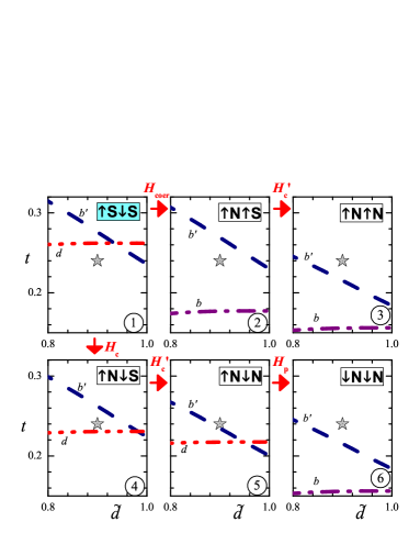
If the applied field is greater than the critical field for the outer S′ layer (), the superconductivity is destroyed, and the system undergoes a transition into the FMN state (panel 3 of Fig. 5). In other words, the information written using the S′ supercurrent changes as well. Note that one can call the transition from superconducting to normal state that is controlled by the external magnetic field to be the transition with practically infinite magnetoresistance 444In this case for the transition between superconducting () and normal () states we formally have ..
Thus, these transitions can be written as follows (see also panels 1-3 of Fig. 5 for details): SS NS NN.
Applying the external magnetic field in the opposite direction () it is possible to induce the other three additional transitions of the system. In principle it is necessary to distinguish the critical fields for the S and S′ layers. Moreover these fields can be different for the same four-layered samples in the AFM and FM configurations. For the “star” working point and the AFM ordering, we have to put that , since the difference is larger than (in Fig. 3 and in panel 1 of Fig. 5 the curve is above the one at ). Note that generally the required magnitudes of the corresponding critical fields and are determined by an appropriate choice of the working point position relative to the curves of the superconducting transition and , respectively (see Fig. 3). In addition, by changing and one can be always made smaller than the field , which is necessary to remove pinning.
If is a bit larger than but is less than the system undergoes a transition from the ground AFMS state into the mixed AFM state: SS NS (see also panels 1,4 of Fig. 5). Only the information that is stored using the superconducting property of the S layer changes, while the stored data associated with ordering of the magnetizations of both F and F′ layers and the S′ supercurrent remain unchanged. The final transitions in this series take place at further increase of the magnetic field (from being to ) in the same “downward” direction: NS NN NN (see also panels 4-6 of Fig. 5).
Thus the F/S/F′/S′ system prepared in such a way has six logically different states: SS, NS, NN, NS, NN, NN (see also Fig. 5). Recall that in the case of the symmetric F/S superlattice the superconducting properties vary synchronously in all S layers, and a similar device on its base has up to five logically different states Proshin et al. (2001); Khusainov et al. (2001); Izyumov et al. (2002); Proshin et al. (2002). Note also that only two states were proposed for the trilayer spin switch Buzdin et al. (1999); Tagirov (1999).
Consider another choice of parameters (, ) in Fig. 3 that corresponds to the “diamond” working point with four operating states. At zero magnetic field the system is in the region that corresponds to the mixed AFM state (see Fig. 4), for which the inner S layer is superconducting, and the outer S′ one is normal. In this case a “short” chain of transitions can be obtained by changing the directed “upwards” magnetic field (i.e. ): SN NN. The “longer” chain of transitions is obtained when the direction of magnetic field is changed to the opposite (i.e. ): SN NN NN. Thus, there are altogether only four different states.
Finally, if we choose the “triangle” working point (, ) in Fig. 3, it is possible to obtain up to seven logically different states. The successive change of the magnitude of the directed “upwards” magnetic field leads to the following chain of transitions of the system: SS SS NS NN. Changing the direction of the field to the opposite one can obtain the following chain: SS SN NN NN. As it follows from the phase diagram in Fig. 3, we have used the assumption that for the FM configuration and for the AFM one while considering the last working point. Moreover, if the “triangle” position were moved a little to the left (), then for the FM configuration and we would get the chain of transitions consisting of six different states.
It follows from our studies that the “spin switch” device proposed on the basis of a F/S/F trilayer Buzdin et al. (1999); Tagirov (1999) (even with the optimum set of parameters that we have found) has much less number of logically different ways of data recording than the studied above four-layered F/S/F′/S′ system.
VI Conclusions
The four-layered F/S/F′/S′ system has been consistently studied within the modern theory of the proximity effect with a detailed account of the given boundary conditions. Theoretical studies of the critical temperature dependence on the thicknesses of the F layers have been performed for a wide range of parameters, and a physically interesting range of their values has been determined. The latter should be of help in choosing materials and technology for preparation of the F/S systems with predetermined properties.
It has been shown that when the phase superconductivity coexists with the nonequivalence of all layers the physics of the four-layered systems is considerably richer in comparison with one for the the earlier studied three-layered F/S/F system Buzdin et al. (1999); Tagirov (1999) and even the F/S superlattices Khusainov et al. (2001); Proshin et al. (2001); Izyumov et al. (2002). The extra phase superconducting states obtained for the four-layered F/S/F′/S′ system have been found to be different from the analogous phase superconducting superlattice states. The hierarchy of critical temperatures has been shown to manifest itself mainly through the occurrence of the different critical temperatures in the different S and S′ layers (space-separated or decoupled superconductivity). This prediction can be experimentally verified both for the common case and for the specially prepared field-cooled FM and AFM samples.
Theoretical studies performed in this paper have shown that the four-layered F/S/F′/S′ system has the best prospects for its use in superconducting spin electronics (superconducting spintronics). This system can be used for a creation of the nanoelectronics devices combining within the same layered sample the advantages of the superconducting and magnetic channels of data recording that are associated with the conducting properties of both S and S′ layers and the magnetic ordering of the magnetizations of the ferromagnetic layers. It has been emphasized that both these channels can be separately controlled by a external magnetic field. These magnetic fields can be made sufficiently weak 4646footnotemark: 46 due to a choice of materials and parameters of the system. A few versions of the principal scheme of such a four-layered F/S/F′/S′ device have been proposed and explored. It has been shown that the proposed control device can have up to seven different states, and transitions between these states can be controlled by a magnetic field. It should be noted that advantages of such spin devices are also associated with their small enough sizes (thickness is about nm, thickness nm), relatively high switching speed (according to estimates Clinton and Johnson (1997) its range is from s-1 up to s-1 depending on used materials), relatively large critical currents (they approximately coincide with currents for isolated superconductors Tagirov (1999)). Certainly, low temperatures at which usual “cold” superconductivity is possible would be a condition for the use of this type of control device. However, similar superconducting devices on the basis of the F/S structures with S layers made out of high-temperature superconducting materials Habermeier and Cristiani (2004) should work at much higher temperatures.
Finally, it should be noted that certain simplifications that were introduced in the performed studies do not impose any serious restrictions on the applicability of the main results obtained in the present paper (hierarchy of critical temperatures, phase diagram in Fig. 4, proposed schemes of a control device, etc.) that provide qualitative understanding and principal solutions of the problem. The model approach used in our studies adequately describes physics of the F/S/F′/S′ system. Though taking into account the multi-mode approach Fominov et al. (2001, 2002) and/or the 3D treatmentIzyumov et al. (2002); Khusainov and Proshin (2003); Izyumov et al. (2000) could change the shape of the curves in the discussed above diagrams for the same values of parameters, it is always possible to change this set of values in such a way that similar graphs can be constructed. The effect of the influence of each parameter change on the shape of the phase curves was discussed in the review Izyumov et al. (2002).
Acknowledgements.
Yu.P. and M.Kh. are grateful to the Max-Planck-Institute for the Physics of Complex Systems (Dresden) for providing excellent conditions for fruitful work. Yu.P. thanks Prof. Fulde and the participants of his seminar for the productive discussion of the results presented in this paper. This work was supported in part by RFBR (No 04-02-16761, 05-02-16369), and the University of Texas at Arlington Research Enhancement Program.References
- Ginzburg (1956) V. L. Ginzburg, Zh. Eksp. Teor. Fiz. 31, 202 (1956), [Sov. Phys. JETP 4, 153 (1957)].
- Chandrasekhar (1962) B. S. Chandrasekhar, Appl. Phys. Lett. 1, 7 (1962).
- Clogston (1962) A. I. Clogston, Phys. Rev. Lett. 9, 266 (1962).
- Izyumov et al. (2002) Y. A. Izyumov, Y. N. Proshin, and M. G. Khusainov, Usp. Fiz. Nauk 172, 113 (2002), [Physics-Uspekhi 45, 109 (2002)].
- Ryasanov et al. (2004) V. V. Ryasanov, V. A. Obosnov, A. S. Procof’ev, V. V. Bolginov, and A. K. Feofanov, J. Low Temp. Phys. 136, 385 (2004).
- Buzdin (2005) A. Buzdin, Rev. Mod. Phys. 77, 935 (2005).
- Radović et al. (1991) Z. Radović, M. Ledvij, L. Dobrosavljević-Grujić, A. I. Buzdin, and J. R. Clem, Phys. Rev. B 44, 759 (1991).
- Buzdin et al. (1992) A. I. Buzdin, B. Vujićić, and M. Y. Kupriyanov, Zh. Eksp. Teor. Fiz. 101, 231 (1992), [Sov. Phys. JETP 74, 124 (1992)].
- Bulaevskii et al. (1977) L. N. Bulaevskii, V. Kuzii, and A. Sobyanin, Pis ma Zh. Eksp. Teor. Fiz. 25, 314 (1977), [JETP Lett. 25, 290 (1977)].
- Khusainov and Proshin (1997) M. G. Khusainov and Y. N. Proshin, Phys. Rev. B 56, 14283 (1997), {see also Phys. Rev. B 62, 6832 (2000)}.
- Proshin and Khusainov (1997) Y. N. Proshin and M. G. Khusainov, Pis’ma Zh. Eksp. Teor. Fiz. 66, 527 (1997), [JETP Lett. 66, 562 (1997)].
- Proshin and Khusainov (1998) Y. N. Proshin and M. G. Khusainov, Zh. Eksp. Teor. Fiz. 113, 1708 (1998), {see also Zh. Eksp. Teor. Fiz. 116, 1882 (1999)} [JETP 86, 930 (1998) {89, 1021 (1999)}].
- Aarts et al. (1997) J. Aarts, J. M. E. Geers, E. Brück, A. A. Golubov, and R. Coehoorn, Phys. Rev. B 56, 2779 (1997).
- Tagirov (1998) L. R. Tagirov, Physica C 307, 145 (1998).
- Fominov et al. (2001) Y. V. Fominov, N. M. Chtchelkatchev, and A. A. Golubov, Pis’ma Zh. Eksp. Teor. Fiz. 74, 101 104 (2001), [JETP Lett. 74, 96 (2001)].
- Fominov et al. (2002) Y. V. Fominov, N. M. Chtchelkatchev, and A. A. Golubov, Phys. Rev. B 66, 014507 (2002).
- Bagrets et al. (2003) A. Bagrets, C. Lacroix, and A. Vedyayev, Phys. Rev. B 68, 054532 (2003).
- Izyumov et al. (2000) Y. A. Izyumov, Y. N. Proshin, and M. G. Khusainov, Pis’ma Zh. Eksp. Teor. Fiz. 71, 202 (2000), [JETP Lett. 71, 138 (2000)].
- Garifullin et al. (2002) I. A. Garifullin, D. A. Tikhonov, N. N. Garif’yanov, L. Lazar, Y. V. Goryunov, S. Y. Khlebnikov, L. R. Tagirov, K. Westerholt, and H. Zabel, Phys. Rev. B 66, 020505(R) (2002).
- Larkin and Ovchinnikov (1964) A. I. Larkin and Y. N. Ovchinnikov, Zh. Eksp. Teor. Fiz. 47, 1136 (1964), [Sov. Phys. JETP 20, 762 (1965)].
- Fulde and Ferrell (1964) P. Fulde and R. A. Ferrell, Phys. Rev. A135, 550 (1964).
- Demler et al. (1997) E. A. Demler, G. B. Arnold, and M. R. Beasley, Phys. Rev. B 55, 15174 (1997).
- Khusainov and Proshin (2003) M. G. Khusainov and Y. N. Proshin, Usp. Fiz. Nauk 173, 1385 (2003), [Physics-Uspekhi 46, 1311 (2003)].
- Buzdin et al. (1999) A. I. Buzdin, A. V. Vedyayev, and N. V. Ryzhanova, Europhys. Lett. 48, 686 (1999).
- Tagirov (1999) L. R. Tagirov, Phys. Rev. Lett. 83, 2058 (1999).
- Bergeret et al. (2000) F. S. Bergeret, K. B. Efetov, and A. I. Larkin, Phys. Rev. B 62, 11872 (2000).
- Bergeret et al. (2004) F. S. Bergeret, A. F. Volkov, and K. B. Efetov, Phys. Rev. B 69, 174504 (2004).
- Bergeret et al. (2001) F. S. Bergeret, A. F. Volkov, and K. B. Efetov, Phys. Rev. Lett. 86, 4096 (2001).
- Bergeret et al. (2003) F. S. Bergeret, A. F. Volkov, and K. B. Efetov, Phys. Rev. B 68, 064513 (2003).
- Volkov et al. (2003) A. F. Volkov, F. S. Bergeret, and K. B. Efetov, Phys. Rev. Lett. 90, 117006 (2003).
- Fominov et al. (2003) Y. V. Fominov, A. A. Golubov, and M. Y. Kupriyanov, Pis’ma Zh. Eksp. Teor. Fiz. 77, 609 (2003), [JETP Lett. 77, 510 (2003)].
- Khusainov et al. (2001) M. G. Khusainov, Y. A. Izyumov, and Y. N. Proshin, Pis’ma Zh. Eksp. Teor. Fiz. 73, 386 (2001), [JETP Letters 73, 344 (2001)].
- Proshin et al. (2001) Y. N. Proshin, Y. A. Izyumov, and M. G. Khusainov, Phys. Rev B. 64, 064522 (2001).
- Goff et al. (2002) J. P. Goff, P. P. Deen, R. C. C. Ward, M. R. Wells, S. Langridge, R. Dalgleish, S. Foster, and S. Gordeev, JMMM 240, 592 (2002).
- Oh et al. (1997) S. Oh, D. Youm, and M. R. Beasley, Appl. Phys. Lett. 71, 2376 (1997).
- Clinton and Johnson (1997) T. W. Clinton and M. Johnson, Appl. Phys. Lett. 70, 1170 (1997).
- Gu et al. (2002) J. Y. Gu, C.-Y. You, J. S. Jiang, J. Pearson, Y. B. Bazaliy, and S. D. Bader, Phys. Rev. Lett. 89, 267001 (2002).
- Proshin et al. (2002) Y. Proshin, Y. Izyumov, and M. G. Khusainov, Supercond. Sci. Techn. 15, 285 (2002).
- de Gennes (1964) P. G. de Gennes, Rev. Mod. Phys. 36, 225 (1964).
- Dieny et al. (1991) B. Dieny, V. S. Speriosu, S. S. P. Parkin, B. A. Gurney, D. R. Wilhoit, and D. Mauri, Phys. Rev. B 43, 1297 (1991).
- Habermeier and Cristiani (2004) H.-U. Habermeier and G. Cristiani, Physica status solidi (a) 201, 1436 (2004).
- Kittel (1975) C. Kittel, Introduction to Solid State Physics (J. Willey and Sons, NY, 1975).
- Rusanov et al. (2004) A. Y. Rusanov, M. Hesselberth, J. Aarts, and A. I. Buzdin, Phys. Rev. Lett. 93, 057002 (2004).