vario\fancyrefseclabelprefixSection #1 \frefformatvariothmTheorem #1 \frefformatvariolemLemma #1 \frefformatvariocorCorollary #1 \frefformatvariodefDefinition #1 \frefformatvarioobsObservation #1 \frefformatvarioasmAssumption #1 \frefformatvario\fancyreffiglabelprefixFig. #1 \frefformatvarioappAppendix #1 \frefformatvariopropProposition #1 \frefformatvarioalgAlgorithm #1 \frefformatvario\fancyrefeqlabelprefix(#1)
Massive MU-MIMO-OFDM Downlink with
One-Bit DACs and Linear Precoding
Abstract
Massive multiuser (MU) multiple-input multiple-output (MIMO) is foreseen to be a key technology in future wireless communication systems. In this paper, we analyze the downlink performance of an orthogonal frequency division multiplexing (OFDM)-based massive MU-MIMO system in which the base station (BS) is equipped with 1-bit digital-to-analog converters (DACs). Using Bussgang’s theorem, we characterize the performance achievable with linear precoders (such as maximal-ratio transmission and zero forcing) in terms of bit error rate (BER). Our analysis accounts for the possibility of oversampling the time-domain transmit signal before the DACs. We further develop a lower bound on the information-theoretic sum-rate throughput achievable with Gaussian inputs.
Our results suggest that the performance achievable with 1-bit DACs in a massive MU-MIMO-OFDM downlink are satisfactory provided that the number of BS antennas is sufficiently large.
I Introduction
Massive multiuser (MU) multiple-input multiple-output (MIMO) is foreseen to be one of the key technologies in fifth-generation (5G) cellular systems. Massive MU-MIMO deploys a large number of antennas at the base station (BS), which enables significant improvements in terms of spectral efficiency, energy efficiency, reliability, and coverage compared to traditional small-scale MIMO [1, 2].
However, increasing the number of BS antennas by orders of magnitude may lead to a significant growth in the circuit power consumption, system costs, and hardware complexity. To compensate for this, it is necessary to deploy practical massive MU-MIMO systems with cheap, power-efficient, and low-complexity hardware components. However, such inexpensive and energy-efficient analog circuitry may fundamentally limit the capacity of the system, due to hardware imperfections.
One of the most dominant sources of power consumption in massive MU-MIMO architectures are the data converters at the BS. Today’s state-of-the-art multi-antenna BSs deploy high-resolution (e.g., 10-bit or more) digital-to-analog converters (DACs) at each radio frequency (RF) port for downlink transmission. However, scaling up this approach to massive MU-MIMO systems with hundreds or thousands of BS antenna elements seems infeasible. Indeed, apart from system costs and power consumption, such an approach may also result in a bandwidth overload on the fronthaul link connecting the baseband processing unit to the RF ports. A natural approach to address all of these issues is to reduce the resolution of the DACs used at the BS. In this paper, we shall consider the extreme case of a BS equipped with 1-bit-resolution DACs and investigate the downlink performance achievable with linear precoders over frequency-selective fading channels.
Relevant prior art
The performance achievable in the massive MU-MIMO uplink (users communicate to the BS) when the BS is equipped with 1-bit analog-to-digital converters (ADCs) has been investigated recently in [3, 4, 5, 6]. These results have shown that 1-bit-ADC massive MU-MIMO architectures yield high information-theoretic sum-rate throughput despite the severe nonlinearity introduced by the 1-bit ADCs, provided that the number of BS antennas is sufficiently large.
In contrast to these results, far less is known about the impact on performance of the use of 1-bit DACs in the massive MU-MIMO downlink (BS communicates to users). For the frequency-flat case, the performance of linear precoders such as maximal-ratio transmission (MRT) and zero-forcing (ZF) in the massive MU-MIMO downlink with 1-bit DACs at the BS has been analyzed in [7, 8, 9]. Similarly to the uplink case, it has been shown that it is possible to achieve low bit error rates (BERs) and high sum-rate throughput despite the nonlinearity introduced by the 1-bit DACs. More sophisticated nonlinear precoders were proposed recently, again for the frequency-flat case, in [9, 10, 11, 12, 13, 14]. These nonlinear precoders yield significant performance gains over linear precoders, at the cost of an increased signal-processing complexity. It is, however, an open question whether the nonlinear precoders proposed in the literature can be extended to frequency-selective channels while maintaining a low computational complexity.
All results reviewed so far deal with single-carrier modulation over a frequency-flat channel. To our knowledge, the only work that considers 1-bit DACs combined with orthogonal frequency division multiplexing (OFDM)—the setup we shall focus on in the present paper—is [15]. There, using an approximate model for the distortion caused by the 1-bit DACs at the BS, it is shown that MRT precoding yields a manageable distortion level at the user equipments (UEs), provided that the number of BS antennas is sufficiently large. However, the analysis in [15] is limited to symbol-rate sampling DACs and the performance of this architecture in terms of BER or achievable rates is not discussed.
Contributions
We characterize the performance achievable in the MU-MIMO-OFDM downlink for systems in which the BS is equipped with 1-bit DACs. In contrast to previous works [7, 8, 12, 13, 9, 10, 11], we assume OFDM transmission over a frequency-selective channel. Furthermore, our analysis supports oversampling DACs. In contrast, the results available in the literature apply only to the case of symbol-rate sampling. Using Bussgang’s theorem [16], we develop a closed-form expression for the signal-to-interference-noise-and-distortion ratio (SINDR) of linear precoders. We then use this expression to obtain (i) an accurate approximation of the uncoded BER achievable with QPSK signaling and (ii) a lower bound on the achievable sum-rate downlink throughput. This lower bound corresponds to the rate achievable using Gaussian signaling and mismatched nearest-neighbor decoding at the UEs. We use numerical simulations to demonstrate that the use of 1-bit DACs and linear precoders in a massive MU-MIMO-OFDM system operating over a frequency-selective Rayleigh-fading channel yields high downlink sum-rate throughput and low BER.
Notation
Lowercase and uppercase boldface letters designate column vectors and matrices, respectively. For a matrix , we denote its transpose and its Hermitian transpose by , and , respectively. The entry on the th row and on the th column of the matrix is denoted as . Furthermore, the th entry of a vector is denoted as . The main diagonal of is . The matrix is a diagonal matrix with the elements of along its main diagonal. The identity matrix and the all-zeros matrix are denoted by and , respectively. The real and imaginary parts of a complex-valued vector are and , respectively. We use to denote the signum function, which is applied entry-wise to vectors and is defined as if and if . The multivariate complex-valued circularly-symmetric Gaussian probability density function with covariance matrix is denoted by . We use to denote expectation with respect to the random variable and to denote the tail probability of the standard normal distribution.
II System Model
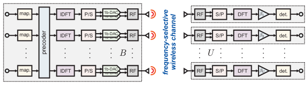
We consider the downlink of a single-cell massive MU-MIMO-OFDM as depicted in \freffig:overview. The BS, which is equipped with antennas, serves single-antenna UEs simultaneously and in the same frequency band. At the BS, a precoder maps the data symbols into precoded symbols to be sent to the RF ports. Since the system is assumed to operate over a frequency selective channel, OFDM is used. Specifically, the frequency-domain precoded vector is transformed into a time-domain vector by performing an inverse discrete Fourier transform (IDFT) at each RF port. Then, the resulting signal is generated by a pair of 1-bit DACs, one operating on the real part and one on the imaginary part of the time-domain signal. At the UEs, the received time-domain signal is mapped back to the frequency domain through a DFT.
II-A OFDM Numerology
Each OFDM symbol consists of data symbols and subcarriers. Let be the subcarrier spacing and the sampling rate of the DACs. We use the disjoint sets and to denote the set of subcarriers designated for data symbols (occupied subcarriers) and for guard subcarriers, respectively. The number of occupied subcarriers is , and the number of guard subcarriers is . Let denote the -dimensional data vector associated with the th () subcarrier. We shall assume that if and that if . Note that the case corresponds to symbol-rate sampling whereas setting yields an oversampling ratio (OSR) of .
II-B Time-Domain Channel Input-Output Relation
For simplicity, we assume that all RF hardware components other than the DACs (e.g., local oscillators, mixers, power amplifiers, etc.) are ideal and that the ADCs at the UEs have infinite resolution. We also assume that the sampling rate of the DACs at the BS is equal to the sampling rate of the ADCs at the UEs and that the system is perfectly synchronized. Under these assumptions, the received discrete-time baseband vector containing the samples at discrete time of the signals received at the UEs can be written as
| (1) |
Here, is the quantized time-domain precoded vector at time , the matrix is the time-domain channel matrix associated with the th channel tap of the frequency-selective channel (). This matrix has entries . We further assume the entries of the matrices to be independent and to remain constant for the duration of an OFDM symbol. Note that these assumptions yield a spatially white frequency-selective Rayleigh-fading channel with uniform power-delay profile. An extension to spatially correlated channels and to other power-delay profiles is straightforward. Finally, denotes the additive white Gaussian noise (AWGN) at the UEs. Here, stands for the noise power spectral density (PSD).
At time , the quantized time-domain precoded vector is obtained by passing the infinite-resolution time-domain precoded vector through a set of 1-bit DACs.111In \frefsec:linear_precoding, we shall describe how this vector is obtained from the data symbols for . Specifically, let , where stands for the average transmit power at the BS. We have that where the nonlinear function , which captures the operation of the DACs, is defined as
| (2) |
A cyclic prefix of length is prepended to the time-domain precoded vector and is later discarded at the receive side. We shall not explicitly prepend the cyclic prefix to to keep notation compact. The cyclic prefix makes the channel matrix circulant and, hence, diagonalizable through IDFT and DFT operations at the BS and UE sides.
II-C Frequency-Domain Channel Input-Output Relation
Let and be the time-domain transmitted and received matrices over the time instants, respectively. Furthermore, let and be the corresponding frequency-domain matrices. Here, stands for the DFT matrix, which satisfies . Finally, let
| (3) |
be the frequency-domain channel matrix associated with the th subcarrier. After discarding the cyclic prefix, we can write the frequency-domain input-output relation at the th subcarrier as
| (4) |
Here, and are the th column of and , respectively. Furthermore, is the th column of the matrix , where .
II-D Linear Precoding
In this paper, we shall focus exclusively on linear precoding strategies. We assume that the BS has perfect knowledge of the realizations of the frequency-domain channel matrices for (a relaxation to the case of imperfect channel-state information will be considered in future works). We further assume that the time-domain precoded vector is obtained from the data symbols as follows:
| (5) |
for . In words, the data symbols on the th subcarrier are multiplied with the frequency-domain precoding matrix . The resulting frequency domain vector is then converted into time domain through an IDFT. We use the convention that on all guard subcarriers, i.e., for all subcarriers that satisfy .
We focus on two linear precoders that are commonly used in the infinite-resolution case, namely MRT and ZF. With MRT, the BS maximizes the power directed towards each UE, ignoring MU interference. This is done by setting the precoding matrix equal to the Hermitian transpose of the channel matrix. With ZF, the BS avoids MU interference by setting the precoding matrix equal to the pseudo-inverse of the channel matrix. Mathematically, we have
| (6) |
Here, and are scaling factors chosen to ensure that the power constraint is satisfied in the infinite-resolution case.
III Performance Analysis
In the infinite-resolution case, the frequency-domain received signal can be written as
| (7) |
In words, the received signal on subcarrier depends only on and not on the data symbols transmitted on other subcarriers. Hence, each subcarrier can be analyzed separately. In the 1-bit-DAC case, however, the received signal on one subcarrier depends, in general, on the data symbols transmitted on all other subcarriers. For a performance analysis, it is convenient to use the Kronecker product property and to write the frequency-domain received signal in vectorized form as
| (8) |
Here, , , and is the block-diagonal matrix that has the matrices on its main diagonal. In (8), the quantized time-domain precoded vector is given by where and where . Now let denote the block-diagonal matrix that has the matrices on its main diagonal. We can write the time-domain precoded vector as
| (9) |
where , and where . Now, using (9) in (8), we obtain
| (10) |
Next, we use Bussgang’s theorem [16] to decompose (10) in a form that enables analytic analysis. Bussgang’s theorem has previously been used in, e.g., [6, 5, 7, 8, 9], to characterize the performance of the quantized single-carrier massive MU-MIMO uplink and downlink on frequency-flat channels. Here, we generalize these analyses for the downlink to the frequency-selective case.
III-A Decomposition Using Bussgang’s Theorem
The 1-bit DACs introduce an error that is correlated with . For Gaussian inputs, Bussgang’s theorem [16] allows us to decompose into two components: a linear function of and a distortion that is uncorrelated with . Specifically, let for all . By using Bussgang’s theorem, the quantized time-domain precoded vector can be written as [17, 9]
| (11) |
where is a distortion that is uncorrelated with . Furthermore, is a diagonal matrix, where (cf. [9, Eq. (14)])
| (12) |
Inserting (11) into (10) we obtain
| (13) | |||||
| (14) |
The last step follows because .
III-B Achievable Sum-Rate with Gaussian Inputs
Let denote the received signal on the th subcarrier at the th UE. It follows from (14) that
| (15) | |||||
The first term on the right-hand side of (15) corresponds to the desired signal; the second term captures the MU interference; the third term describes the distortion introduced by the quantizer; the fourth term represents AWGN.
Let now be the SINDR on the th subcarrier for the th UE. Using (15), we can express as
| (16) |
where we have defined
| (17) |
where . Let now
| (18) |
Since and are uncorrelated, it follows from (11) that
| (19) |
where has the following closed-form expression for the case of 1-bit DACs [18]:
| (20) | |||||
Through standard manipulations of the mutual information (see, e.g., [9]), we can obtain a lower bound on the sum-rate throughput that is explicit in the SINDR (16) as follows:
| (21) |
This lower bound corresponds to the rate achievable with a Gaussian codebook and a mismatched nearest-neighbor decoder at the UEs [19, 20].
IV Numerical Results
We focus on a MU-MIMO-OFDM system in which the number of BS antennas is and the number of UEs is . We consider a frequency-selective Rayleigh-fading channel with taps and a uniform power delay profile. The OFDM numerology is inspired by an LTE system [21]. Specifically, we assume that the number of occupied subcarriers is . The subcarrier spacing is kHz and the total number of subcarriers (the size of the DFT) is . Hence, the sampling rate of the DACs is and the OSR is .
IV-A Spectral Emissions
In \freffig:spectrum, we plot the normalized PSD of the transmitted signal (averaged over the BS antennas and the channel realizations) and the PSD of the received signal (averaged over the UEs and the channel realizations). We assume that the BS uses MRT precoding and that the data vector contains uncoded QPSK symbols. Furthermore, we assume that the occupied carriers are the first 150 to the left and to the right of the DC carrier (the DC carrier is not occupied). This results in a one-sided bandwidth of MHz (the available one-sided bandwidth is instead MHz).
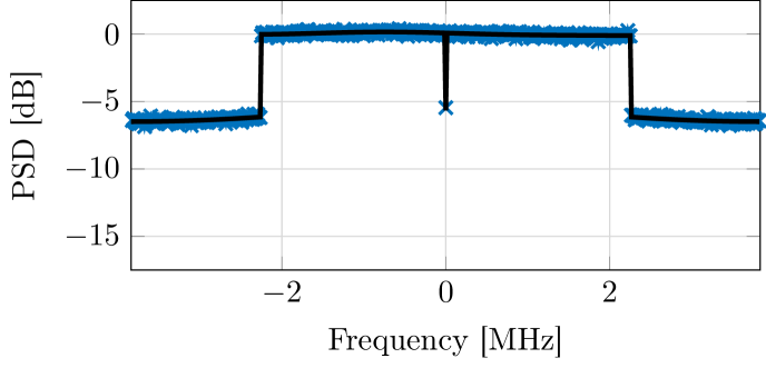
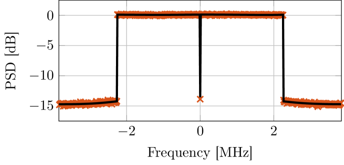
Numerical simulations are compared with analytic results obtained by computing the PSD of and of the corresponding output vector using (20). We see from the figure that the nonlinearity introduced by the 1-bit-DAC causes severe out-of-band (OOB) distortion at the BS. Interestingly, however, the OOB distortion of the received signal at the UE is roughly dB smaller than the OOB distortion of the transmitted signal at the BS. This is because the distortion adds up incoherently at the UEs whereas the useful signal is beamformed to the UEs. Hence, even though the 1-bit DACs cause significant spectral distortions per antenna, the distortion levels at the UEs are not as severe. Nevertheless, the OOB distortion caused by the 1-bit DACs is a significant issue in practical systems as it may cause interference to UEs in adjacent frequency bands.
IV-B Error-Rate Performance
IV-B1 Uncoded BER
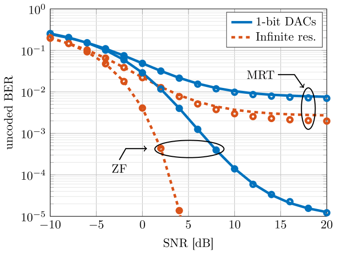
In \freffig:ber_tap_uncoded, we plot the uncoded BER with QPSK for MRT and ZF precoding as a function of the SNR . Both the case of 1-bit DACs and of infinite-resolution DACs are considered. The simulated BER values are compared with an analytical approximation for the BER obtained by assuming that the overall noise at the UEs (which includes MU inteference and quantization errors) is Gaussian. Under this assumption, the uncoded BER with QPSK can be approximated by
| (22) |
where is given in (16). We see from \freffig:ber_tap_uncoded that MRT suffers from a relatively high error floor, which is mainly due to residual MU interference, whereas ZF yields better performance, although the gap at from the performance obtainable with infinite-resolution DACs is about dB. The approximation (22) is accurate over the entire range of SNR values considered in the figure. This suggests that the overall noise per subcarrier at the UEs can indeed be modeled accurately as a Gaussian random variable.
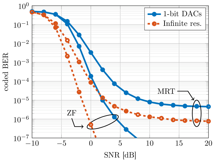
IV-B2 Coded BER
In \freffig:ber_tap_coded we show the coded BER for MRT and ZF, for the case of QPSK modulation and rate- convolutional code. The length of the codewords is bits and the QPSK symbols are randomly interleaved over consecutive OFDM symbols. The UEs perform symbol-wise nearest-neighbor decoding and hard-input Viterbi decoding (extension to soft-input decoding is part of ongoing work). With ZF, the gap to the infinite-resolution performance is dB for a target BER of . As in the uncoded case, MRT is limited by MU interference; the error floor is, however, below .
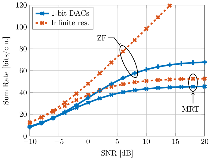
IV-C Achievable Rate
In \freffig:rate, we show the sum-rate throughput (21) achievable with Gaussian inputs and mismatched nearest-neighbor decoding as a function of the SNR. We observe that, similarly to the frequency-flat case [9], a high sum-rate throughput can be achieved. Specifically, a sum-rate throughput exceeding -bits per channel use (corresponding to bits per channel use per UE) can be achieved for SNR values beyond dB.
IV-D Impact of Oversampling

In \freffig:osr, we investigate the impact of the OSR on the uncoded BER. Specifically, we plot the uncoded BER for the case of uncoded QPSK as a function of the OSR for both MRT and ZF. The SNR, defined as , is set to dB. We note that, for ZF, the uncoded BER can be considerably improved by operating the DACs at a sampling rate higher than the symbol rate. Indeed, the uncoded BER with ZF can be decreased by an order of magnitude compared to the symbol-rate sampling case (OSR) by operating the DACs at twice the symbol rate. However, further increasing the sampling rate yields only marginal performance gains.
V Conclusions
We have characterized the performance in terms of BER and achievable rate of a MU-MIMO-OFDM downlink system, where the BS is equipped with 1-bit DACs and uses linear precoding. Using Bussgang’s theorem, we have obtained a closed-form expression for the SINDR, which we have then used to obtain a lower bound on the achievable sum-rate with Gaussian inputs and an accurate approximation for the uncoded BER with QPSK. Through numerical simulations, we have illustrated that low uncoded and coded BERs and high sum-rates are achievable despite the severe nonlinearity introduced by the 1-bit DACs, at the cost of unwanted OOB emissions.
Extensions of our analysis to the case of multi-bit DACs and to nonlinear precoders is part of ongoing work. Developing methods for reducing OOB emissions is also part of ongoing work.
References
- [1] F. Rusek, D. Persson, B. Kiong, E. G. Larsson, T. L. Marzetta, O. Edfors, and F. Tufvesson, “Scaling up MIMO: Opportunities and challenges with very large large arrays,” IEEE Signal Process. Mag., vol. 30, no. 1, pp. 40–60, Jan. 2013.
- [2] E. G. Larsson, F. Tufvesson, O. Edfors, and T. L. Marzetta, “Massive MIMO for next generation wireless systems,” IEEE Commun. Mag., vol. 52, no. 2, pp. 186–195, Feb. 2014.
- [3] C.-K. Wen, C.-J. Wang, S. Jin, K.-K. Wong, and P. Ting, “Bayes-optimal joint channel-and-data estimation for massive MIMO with low-precision ADCs,” IEEE Trans. Signal Process., vol. 64, no. 10, pp. 2541–2556, Jul. 2015.
- [4] C. Mollén, J. Choi, E. G. Larsson, and R. W. Heath Jr., “Uplink performance of wideband massive MIMO with one-bit ADCs,” IEEE Trans. Wireless Commun., vol. 16, no. 1, pp. 87–100, Oct. 2016.
- [5] S. Jacobsson, G. Durisi, M. Coldrey, U. Gustavsson, and C. Studer, “Throughput analysis of massive MIMO uplink with low-resolution ADCs,” IEEE Trans. Wireless Commun., vol. 16, no. 6, pp. 4038–4051, Jun. 2017.
- [6] Y. Li, C. Tao, G. Seco-Granados, A. Mezghani, A. L. Swindlehurst, and L. Liu, “Channel estimation and performance analysis of one-bit massive MIMO systems,” IEEE Trans. Signal Process., vol. 65, no. 15, pp. 4075–4089, Aug. 2017.
- [7] A. K. Saxena, I. Fijalkow, and A. L. Swindlehurst, “Analysis of one-bit quantized precoding for the multiuser massive MIMO downlink,” IEEE Trans. Signal Process., vol. 65, no. 17, pp. 4624–4634, Sep. 2017.
- [8] Y. Li, C. Tao, A. L. Swindlehurst, A. Mezghani, and L. Liu, “Downlink achievable rate analysis in massive MIMO systems with one-bit DACs,” IEEE Commun. Lett., vol. 21, no. 7, pp. 1669–1672, Jul. 2017.
- [9] S. Jacobsson, G. Durisi, M. Coldrey, T. Goldstein, and C. Studer, “Quantized precoding for massive MU-MIMO,” IEEE Trans. Commun., 2017, to appear.
- [10] ——, “Nonlinear 1-bit precoding for massive MU-MIMO with higher-order modulation,” in Proc. Asilomar Conf. Signals, Syst., Comput., Pacific Grove, CA, USA, Nov. 2016, pp. 763–767.
- [11] O. Castañeda, S. Jacobsson, G. Durisi, M. Coldrey, T. Goldstein, and C. Studer, “1-bit massive MU-MIMO precoding in VLSI,” IEEE J. Emerging Sel. Topics Circuits Syst., 2017, to appear.
- [12] H. Jedda, J. A. Nossek, and A. Mezghani, “Minimum BER precoding in 1-bit massive MIMO systems,” in IEEE Sensor Array and Multichannel Signal Process. Workshop (SAM), Rio de Janeiro, Brazil, Jul. 2016.
- [13] H. Jedda, A. Mezghani, J. Munir, F. Steiner, and J. A. Nossek, “Spatial coding based on minimum BER in 1-bit massive MIMO systems,” in Proc. Asilomar Conf. Signals, Syst., Comput., Pacific Grove, CA, USA, Nov. 2016, pp. 753–757.
- [14] O. Tirkkonen and C. Studer, “Subset-codebook precoding for 1-bit massive multiuser MIMO,” in Conf. Inf. Sciences Syst. (CISS), Baltimore, MD, USA, Mar. 2017.
- [15] R. D. J. Guerreiro and P. Montezuma, “Use of 1-bit digital-to-analogue converters in massive MIMO systems,” IEEE Electron. Lett., vol. 52, no. 9, pp. 778–779, Apr. 2016.
- [16] J. J. Bussgang, “Crosscorrelation functions of amplitude-distorted Gaussian signals,” Res. Lab. Elec., Cambridge, MA, Tech. Rep. 216, Mar. 1952.
- [17] H. E. Rowe, “Memoryless nonlinearities with Gaussian inputs: Elementary results,” Bell Labs Tech. J., vol. 61, no. 7, pp. 1519–1525, Sep. 1982.
- [18] J. H. Van Vleck and D. Middleton, “The spectrum of clipped noise,” Proc. IEEE, vol. 54, no. 1, pp. 2–19, Jan. 1966.
- [19] A. Lapidoth, “Nearest neighbor decoding for additive non-Gaussian noise channels,” IEEE Trans. Inf. Theory, vol. 42, no. 5, pp. 1520–1529, Sep. 1996.
- [20] W. Zhang, “A general framework for transmission with transceiver distortion and some applications,” IEEE Trans. Commun., vol. 60, no. 2, pp. 384–399, Feb. 2012.
- [21] 3GPP, “LTE; evolved universal terrestrial radio access (E-UTRA); user equipment (UE) radio transmission and reception,” Apr. 2017, TS 36.101 version 14.3.0 Rel. 14.