Precise simulation of single-hole spin control in quantum dots
Abstract
The precise simulation of the initialization, control, and read-out of a single-hole spin qubit is investigated by accurately solving the extended Anderson impurity model in the real time domain with the hierarchical equations of motion approach. The initialization is realized by the ionization of an exciton with high fidelity. Then, a SU(2) control is achieved via the combination of Larmor procession of the hole spin in Voigt geometry magnetic field and rotation about the optical axis with a geometric phase induced by a picosecond laser pulse. Finally, the read-out of the qubit is implemented through photocurrent recording. Our theory not only reproduces the recent experimental results with one set of internal parameters, but also predicts a maximal fidelity by adjusting the dot-electrode coupling strength.
pacs:
72.15.Qm,73.63.Kv,73.63.-bThe trapped single spin in quantum dots (QDs) is a promising qubit which can be optically controlled within picosecond scale Brunner et al. (2009); Press et al. (2008); De Greve et al. (2011). Therefore, it is a good candidate for integrated circuit in quantum information processing(QIP) with the mature processing technology of semiconductors. In literatures, many achievements have been made in electron spin qubit in QDs Press et al. (2008); Vamivakas et al. (2010); Delteil et al. (2014). However, the non-Markovian hyperfine interaction induces decoherence and drops the fidelity of electron spin control Vink et al. (2009). The valence band holes possess p-type wave function that leaves small residual dipolar interactionFischer et al. (2008), which highly suppresses contact hyperfine interaction and induces longer lifetimes of hole spin than that of electron spin Fallahi, Yılmaz, and Imamoğlu (2010); Chekhovich et al. (2011). Recently, many experiments on single-hole spin qubit have been preformed, including initialization, coherent control and read-out Ardelt et al. (2015); De Greve et al. (2011); Gerardot et al. (2008); Godden et al. (2012).
For the realistic application of hole spin qubit, the high fidelity during the initializing process is the key requirement in any QIP protocol. Among the present methods of initialization, the ionization of an exciton has distinct advantages, which achieved the fidelity of Ardelt et al. (2015). By reducing fine-structure splitting or applying a magnetic field parallel to growth direction, the fidelity high to is reachable Godden et al. (2010); Brash et al. (2015). Moreover, it is fast (in s) enough to meet the requirement that the initialization time should order smaller than decoherence time. As a comparison, the optical pumping Press et al. (2008), one of other methods, can only reach the fidelity of in the time scale of s due to the several loops to prepare a polarized spin state Heiss et al. (2008).
Whereas above experimental investigations have been actively performed, theoretical works are not sufficient so far, and the rate equation is the commonly used method to simulate the hole spin manipulation Breuer and Petruccione (2002). We comment that the rate equation is not accurate enough basing on the following two facts. Firstly, in the QDs-based hole spin qubit, the QD directly couple to metal leads (electrodes) which inevitably impacts on the qubit. Therefore, what we deal with is a typical quantum open system with infinity degree of freedoms of the total density matrix, while the rate equation only concerns the diagonal terms of the reduced density matrix and treats the dot-electrode couplings by low-order perturbation schemes. Secondly, the hole spin qubit system is a typical strongly correlated open system with degree of freedoms of the electron-electron (), hole-hole () and electron-hole () interactions, while the rate equation either neglects this important interaction or treats it in the single electron level.
Obviously, for the theoretical study on hole spin qubit, a non-perturbative approach is highly required to deal with the basic quantum model involving different Coulumb interactions. The hierarchical equations of motion (HEOM) approach we used in the present work can meet this requirement, which nonperturbatively resolves the combined effects of dot-electrode dissipation, Coulumb interactions, and non-Markovian memory Jin, Zheng, and Yan (2008); Li et al. (2012); Ye et al. (2016). In this paper, we start from the extended Anderson impurity model to describe the hole spin qubit, fully considering the Coulumb interactions interaction and the dot-electrode couplings. We deal with this quantum model non-perturbatively in the real time domain to precisely simulate the single-hole spin manipulation.
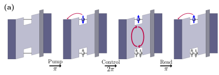
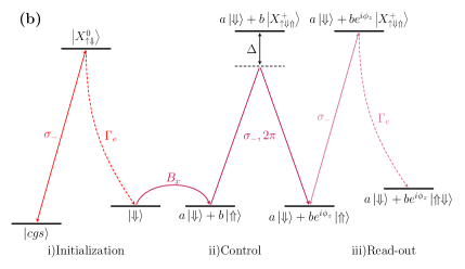
In what follows, via HEOM approach, the whole process of QIP including initialization, coherent control and read-out will be precisely simulated. As will be demonstrated, our theory not only reproduces the recent experimental results in Ref. Godden et al. (2012) with one set of internal parameters, but also predicts a maximal fidelity by adjusting the dot-electrode coupling strength. The complete process of single hole-spin initialization, coherent control and read-out process are sketched in Fig. 1(a) and (b). In order to initialize a single-hole spin , a resonant circularly polarized pulse with pulse area of is used which creates a pair that driving the ground state into a neutral exciton state . Due to the much larger effective mass of holes, the hybridization strength of them is much smaller than that of electrons, i.e. . As a consequence, electrons in conduction level tunnels into electrode in a orders of time magnitude faster than holes, which turns into single-hole spin state quickly. Note that the operation is confined to photocurrent region, we omit the radiative recombination of pair. Then, the applied in-plane magnetic field drives the single-hole spin to precess along axis, which preforms a U(1) operation. In order to realize a SU(2) operation in Bloch sphere, a geometric phase approach is adopted as proposed in Ref.Economou and Reinecke (2007). That with a geometric pulse of a sech envelope, the hole spin undergoes a cycle from single hole state to positive trion state and back to single hole state acquired an rotation angle . After the control sequence, a detection circular polarized pulse is applied, which partially excites the single-hole spin state to positive trion state, accompanied with a photocurrent proportional to the spin-down component of the hole spin state, for which the qubit read-out is achieved via photocurrent detection technique Mar et al. (2013).
By reference of experimental structures, our single-hole spin qubit consists of a QD connecting to two electrodes, which can be described by an extended Anderson impurity Hamiltonian with , and interactions considered. The total Hamiltonian is written as
| (1) |
where and describe the conduction and valence level with and interactions respectively
| (2) | |||
| (3) |
In above equations, and , where annihilates(creates) a conduction level of spin , and similar to the valence level. is the Coulomb repulsion energies if the -level (-level) is double (zero) occupied. The term
| (4) |
accounts for the Coulomb attraction energies between the pair. denotes the interaction of the control field on QD, whose explicit expression will be specified later. The electrodes are modeled by non-interaction electrons
| (5) |
where denotes the creation(annihilation) operator of electron in the specified -electrode spin-orbital state of energy . Nonequilibrium chemical potential with will arise in the presence of bias of voltage. The zero-energy point is set to be at the equilibrium chemical potential . The coupling between the dot and the electrode is described by
| (6) |
It should be noted that due to the large effective mass of holes, transfer matrix element for conduction level is assumed to be much smaller than that of valence level . In the HEOM theory, the influence of electron reservoirs on the dot acts through the hybridization functions with a Lorentzian form , where is the bandwidth and is the chemical potential of lead . The details of HEOM formalism has been developed in Refs. Jin, Zheng, and Yan (2008); Li et al. (2012), and the final HEOM can be cast into a compact form of
| (7) |
where is the reduced density matrix and are auxiliary density matrices at the th-tier. Any observable of the dot system can be calculated in form of . The transient current through the electrode is determined exclusively by the first-tier auxiliary density operators as,
| (8) |
where the index sums from to that counts the contributions both of - and -level. To simulate experiments, we choose the parameters in having the same energy level structure with experiments, as schematically shown in Fig. 1(a), with (the energy unit is all set to meV in rest of this paper), , , , and a reverse bias is applied.
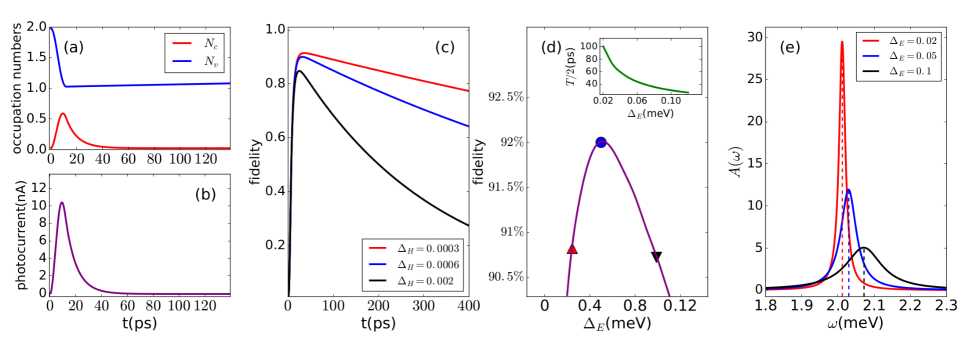
For initialization, a resonant pules with area of 10 ps is applied, with the Hamiltonian , where , , and . The time evolution of occupation numbers of - and -level is presented in Fig. 2(a). As shown in the figure, the maximum of the electron numbers in -level is around 0.62 rather than unity, which is induced by the fast tunneling electron tunneling of the neutral exciton . It will lead to the intensity damping of the Rabi oscillation with increasing electron-electrodes hybridization strength , as a signal of tunneling-induced dephasing Ardelt et al. (2015).
After the pulse applied, it can be seen that the occupation decay is exponential for electrons while approximately linear for holes at ps, due to their different hybridization strength to electrodes. The initialization is achieved at ps, where the electrons in -level has totally escaped into electrodes () and a single hole in -level has been left (). Fig. 2(b) depicts the photocurrent along initialization process. The peak of the photocurrent is shown at the end of the pulse ( ps), where the electrons in -level has maximally accumulated. The charge-photocurrent is precisely conserved, which is responsible for the photocurrent several orders of magnitude larger than the experimental data.
In experiments, in order to achieve high fidelity initialization, an AlGaAs barrier is applied to tailor the tunneling rate of electrons and holes, which effectively changes the conduction and valence level-electrodes hybridization strength. To check this effect theoretically, we investigate the dynamics of fidelity during the excitation-tunneling process at different and . The fidelity is defined via Poyatos, Cirac, and Zoller (1997), which measures the distance between the real evolution and the target evolution to a given initial state . Here the initial state is set to , the target state is the single hole state , which is arrived with two-step (see Fig. 1(b)) process: a) optical excite the crystal ground state to neutral exciton , b) by fast electron tunneling of the neutral exciton to single hole spin . For ideal spin qubit storage with high fidelity, ultrafast -level electron lifetime and long -level hole storage against filling from electrodes are required. Fig. 2(c) shows the time evolution of fidelity with different hole coupling . Noting that the electrons in electrodes fill the hole through the whole process, even at the beginning of the optical excitation. With decreasing hole coupling , storage time for hole increases accordingly. At , as much as of fidelity is observed. This fidelity dynamics can be observed via the photocurrent amplitude of the trion transition with a probe pulse, which reflects the population of single hole spin .
Ideally, one expect a high initialization fidelity with a ultrafast electron tunneling. However, when the electron hybridization strength is comparable to the frequency of the laser which is tuned on resonance with the neutral excitation, it will inevitably bring damage to fidelity. One of these is the tunneling-induced dephasing. Ardelt extract this phenomenon in hole spin initialization with low temperature Ardelt et al. (2015). We comment that compare to rate equation method, the tunneling-induced dephasing is only the consequence of the increasing hybridization strength of electrons in HEOM calculations, but not as a parameter.
The max fidelity appearing in real time scanned with is shown in Fig. 2(d). With increasing , rather than monotonically increase, the fidelity experiences a maximum with at . It should be noted that the couping can induce a energy level shift (the details analysis will be done in Fig. 2(e)) , correspondingly, in order to maximize the fidelity, the frequency of Rabi oscillation should be adjusted as well to satisfy resonance condition. The half of Rabi cycle as a function of is shown in the inset of Fig. 2(d). From the beginning with , as increases, fidelity starts to grows fast at first. This growth is dominated by the shorter electron tunneling time during which the filling of hole is relatively suppressed. However, continue increase that exceeding will bring damage to fidelity, the fidelity drops to lower than with exceeding . In order to explore above impact of electron-electrodes hybridization strength on fidelity, we calculate the single particle spectral function of -level electron with , and , presented in Fig. 2(e). Clearly, due to larger coupling , the spectral function experiences linewidth broadening. The broadening effect can make the single particle level invisible to optical excitation. The ground state only can be partly pumped to neutral exciton state with a adjacent area around zero detuning. Noting that the level broadening plays a role as tunneling-induced damping, as the experiment mentioned above, which can be observed via the broadening of photucurrent absorption spectral Ardelt et al. (2015). The second feature of spectral function is the central position shift. At a small couping , the central position is about , that is exactly the single particle excitation energy with a -level electron tunneling event. When increases to , the central position moves to , meanwhile the fidelity drops to .
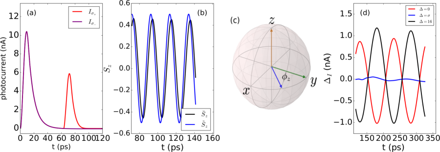
A U(1) rotation of the initialized hole spin state is achieved by applying a magnetic field perpendicular to growth direction to form the Voigt geometry. The down-spin state is a superposition of the eigenstates, which will preform Larmor precession about with frequency determined by the hole Zeeman splitting. To detect the single-hole spin, a co-(cross)-circularly polarized detection pulse with pulse area is used to excites the single hole to positive trion state after a time delay . The resonance frequency of the detection pulse is positively detuned with compared to the initialization pulse, due to the additional Coulomb interaction between the pair. To demonstrate the photocurrent detection of a hole spin in our simulation, we depict the time evolution of photocurrent, the detection pulse is applied at time delay , for which the initialized spin down hole precessed to spin up state . At this time, the excitation of co-circular detection pulse is completely suppressed nevertheless the cross-circular pulse is optical active, which is shown in Fig. 3(a). where and denoting the co-circular and cross-circular excitation respectively.
In experiments, the polarization of the hole spin can be read out via photocurrent using Godden et al. (2012), where is the amplitude of photocurrent peak for the detection pulse . Theoretically, the exact component of hole spin can be directly obtained in form of =tr, which can be used to examine the accuracy of the photocurrent read-out process. Fig. 3(b) shows the comparison between and , with hole hybridization strength , where the overall consistence between and can be seen. Our results of is in agreement with the experiment data in Ref.Godden et al. (2012), therefore, the accuracy of single-hole spin photocurrent read-out technique is verified by Fig. 3(b). When the Rabi frequency and Zeeman splitting energy of the magnetic field is comparable, there exist a small phase difference as shown in the figure, which indicates that the time evolution of is slightly left behind . The phase difference results from the delay of recording photocurrent according the definition of . As shown in Fig. 3(a), the photocurrent reaches its peak value at the end of the pulse, when the hole spin has undergone a precession already. For the parameters used here, Rabi frequency and Zeeman energy , the phase delay is of same magnitude as half of Rabi cycle ps, as presented in Fig. 3(b).
In order to implement a SU(2) control of the hole spin, a control pulse is needed to rotate the spin along second rotation axis. Here we use geometric phase approach, as proposed in theories Economou et al. (2006); Economou and Reinecke (2007), and then successfully realized in experiments Godden et al. (2012); Kim et al. (2010); Greilich et al. (2009). The control pulse is shaped with a hyperbolic secant envelope, with fixed to guarantee no population transferring to trion state after application of the pulse, where is the Rabi frequency and denotes the bandwidth of the pulse. The single-hole spin state acquires a phase factor about -axis via varying detuning from the resonance between the single hole spin state and the positive trion state Economou et al. (2006), as schematically illustrated in Fig. 1(b).
To be concrete, the geometric-phase control pulse is applied after a time delay ps that the hole spin pointing along + axis that the pulse has a maximum effect on the hole spin since the rotation radius is equal to the radius of Bloch sphere, as shown in Fig. 3(c). Carries with the rotation angle , the hole spin continues to precess along axis under the magnetic field, for which the magnitude of geometric phase determines the rotation radius along axis. Since the magnitude of the detection photocurrent is proportional to the hole spin projection on axis, for which one can use the photocurrent difference between detection pulse to pick up the information of the geometric rotation angle . The hole spin procession with different detuning is shown in Fig. 3(d), that is consistent with the experiments in Ref.Godden et al. (2012), where the detection pulses are scanned through the procession. The detunning are set as respectively. For the detunning , the rotation angle is making the spin aligned on + axis that the precession is maximally suppressed with the oscillation amplitude of the photocurrent nearly a constant. Nevertheless for and corresponding to the rotation angle and , the precession radius reaches the maximum as well the oscillation amplitude of photocurrent, with a difference of phase .
In summary, by accurately solving the extended Anderson impurity model in the real time domain with the hierarchical equations of motion (HEOM) approach, we precisely simulate the whole process of single-hole spin control including initialization, SU(2) rotation, and read-out. Our theoretical results are in well agreement with the recent experimental observations, which demonstrates the feasibility and accuracy for the HEOM approach to describe the hole spin dynamics. Particularly, the influence of the hybridization strength to electrodes is fully considered, and a maximal fidelity in the initialization is predicted.
The support from the NSF of China (No.11374363) and the Research Funds of Renmin University of China (Grant No. 11XNJ026) is gratefully appreciated.
References
- Brunner et al. (2009) D. Brunner, B. D. Gerardot, P. A. Dalgarno, G. Wüst, K. Karrai, N. G. Stoltz, P. M. Petroff, and R. J. Warburton, Science 325, 70 (2009).
- Press et al. (2008) D. Press, T. D. Ladd, B. Zhang, and Y. Yamamoto, Nature 456, 218 (2008).
- De Greve et al. (2011) K. De Greve, P. L. McMahon, D. Press, T. D. Ladd, D. Bisping, C. Schneider, M. Kamp, L. Worschech, S. Höfling, A. Forchel, et al., Nat. Phys. 7, 872 (2011).
- Vamivakas et al. (2010) A. Vamivakas, C.-Y. Lu, C. Matthiesen, Y. Zhao, S. Fält, A. Badolato, and M. Atatüre, Nature 467, 297 (2010).
- Delteil et al. (2014) A. Delteil, W.-b. Gao, P. Fallahi, J. Miguel-Sanchez, and A. Imamoğlu, Phys. Rev. Lett. 112, 116802 (2014).
- Vink et al. (2009) I. T. Vink, K. C. Nowack, F. H. Koppens, J. Danon, Y. V. Nazarov, and L. M. Vandersypen, Nat. Phys. 5, 764 (2009).
- Fischer et al. (2008) J. Fischer, W. Coish, D. Bulaev, and D. Loss, Phys. Rev. B 78, 155329 (2008).
- Fallahi, Yılmaz, and Imamoğlu (2010) P. Fallahi, S. Yılmaz, and A. Imamoğlu, Phys. Rev. Lett. 105, 257402 (2010).
- Chekhovich et al. (2011) E. Chekhovich, A. Krysa, M. Skolnick, and A. Tartakovskii, Phys. Rev. Lett. 106, 027402 (2011).
- Ardelt et al. (2015) P.-L. Ardelt, T. Simmet, K. Müller, C. Dory, K. Fischer, A. Bechtold, A. Kleinkauf, H. Riedl, and J. Finley, Phys. Rev. B 92, 115306 (2015).
- Gerardot et al. (2008) B. D. Gerardot, D. Brunner, P. A. Dalgarno, P. Öhberg, S. Seidl, M. Kroner, K. Karrai, N. G. Stoltz, P. M. Petroff, and R. J. Warburton, Nature 451, 441 (2008).
- Godden et al. (2012) T. Godden, J. Quilter, A. Ramsay, Y. Wu, P. Brereton, S. Boyle, I. Luxmoore, J. Puebla-Nunez, A. Fox, and M. Skolnick, Phys. Rev. Lett. 108, 017402 (2012).
- Godden et al. (2010) T. M. Godden, S. J. Boyle, A. J. Ramsay, A. Fox, and M. Skolnick, arXiv preprint arXiv:1006.5842 (2010).
- Brash et al. (2015) A. J. Brash, L. M. Martins, F. Liu, J. H. Quilter, A. J. Ramsay, M. S. Skolnick, and A. M. Fox, Phys. Rev. B 92, 121301 (2015).
- Heiss et al. (2008) D. Heiss, V. Jovanov, M. Bichler, G. Abstreiter, and J. Finley, Phys. Rev. B 77, 235442 (2008).
- Breuer and Petruccione (2002) H.-P. Breuer and F. Petruccione, The theory of open quantum systems (Oxford University Press on Demand, 2002).
- Jin, Zheng, and Yan (2008) J. Jin, X. Zheng, and Y. Yan, J. Chem. Phys. 128, 234703 (2008).
- Li et al. (2012) Z. Li, N. Tong, X. Zheng, D. Hou, J. Wei, J. Hu, and Y. Yan, Phys. Rev. Lett. 109, 266403 (2012).
- Ye et al. (2016) L. Ye, X. Wang, D. Hou, R.-X. Xu, X. Zheng, and Y. Yan, WIREs. Comput. Mol. Sci. (2016).
- Economou and Reinecke (2007) S. E. Economou and T. Reinecke, Phys. Rev. Lett. 99, 217401 (2007).
- Mar et al. (2013) J. Mar, J. Baumberg, X. Xu, A. Irvine, C. Stanley, and D. Williams, Phys. Rev. B 87, 155315 (2013).
- Poyatos, Cirac, and Zoller (1997) J. Poyatos, J. I. Cirac, and P. Zoller, Phys. Rev. Lett. 78, 390 (1997).
- Economou et al. (2006) S. E. Economou, L. Sham, Y. Wu, and D. Steel, Phys. Rev. B 74, 205415 (2006).
- Kim et al. (2010) E. D. Kim, K. Truex, X. Xu, B. Sun, D. Steel, A. Bracker, D. Gammon, and L. Sham, Phys. Rev. Lett. 104, 167401 (2010).
- Greilich et al. (2009) A. Greilich, S. E. Economou, S. Spatzek, D. Yakovlev, D. Reuter, A. Wieck, T. Reinecke, and M. Bayer, Nat. Phys. 5, 262 (2009).