Theoretical prediction of a giant anisotropic magnetoresistance in carbon nanoscrolls
Abstract
Snake orbits are trajectories of charge carriers curving back and forth which form at an interface where either the magnetic field direction or the charge carrier type are inverted. In ballistic samples their presence is manifested in the appearance of magnetoconductance oscillations at small magnetic fields. Here we show that signatures of snake orbits can also be found in the opposite diffusive transport regime. We illustrate this by studying the classical magnetotransport properties of carbon tubular structures subject to relatively weak transversal magnetic fields where snake trajectories appear in close proximity to the zero radial field projections. In carbon nanoscrolls the formation of snake orbits leads to a strongly directional dependent positive magnetoresistance with an anisotropy up to .
keywords:
Carbon nanoscrolls; snake trajectories; perpendicular magnetic field; magnetoresistanceInstitute for Theoretical Solid State Physics, IFW Dresden, Helmholtzstr. 20, 01069 Dresden, Germany
![[Uncaptioned image]](/html/1704.03804/assets/x1.png)
Carbon nanomaterials, such as carbon nanotubes (CNT) 1 and graphene 2, continue to trigger a lot of attention due to their very unique structural and physical properties 3. In recent years, another carbon nanomaterial, called carbon nanoscroll (CNS), has emerged 4. It is a spirally wrapped graphite layer that, unlike a multiwalled carbon nanotube (MWCNT), is open at two edges and does not form a closed structure 5. Scroll whiskers were first reported by Bacon in 1960 6. A more recent chemical route 4 involves intercalation of graphite flakes with potassium followed by exfoliation with ethanol to form a dispersion of carbon sheets. Upon sonication, some of the exfoliated graphite sheets curl into scrolls. The disadvantage of this route is that CNSs are scrolled from an undefined number of graphene layers. In addition, the chemical process can potentially induce unexpected defects in the material, thereby lowering its quality. Controlled fabrication of high-quality CNSs has been instead achieved 7 using isopropyl alcohol solutions to roll up high-quality monolayer graphene predefined on Si/SiO2 substrates. CNSs formation obtained by rolling a graphene monolayer is dominated by two major energetic contributions 5: an elastic energy increase due to bending that decreases the CNS stability, and a free energy gain generated by the van der Waals interaction energy between the overlapping regions of the scroll. Scroll stability requires a minimum layer overlap as well as a minimum inner diameter. Moreover, the inner diameter of the scroll has been predicted 8 to increase up to 2.5% upon charge injection, which suggests that CNSs can be used as efficient electromechanical actuators at the nanometer scale 9. Finally, CNSs can also sustain high current densities, which facilitates their application as microcircuit interconnects7.
The peculiar geometric structure of CNSs also yields unusual electronic 10, optical 11, and transport properties in uniform electric and magnetic fields 12, 13. The natural presence of edge nanoscrolls in graphene, for instance, has been predicted to be at the basis of the poor quantization of the Hall conductance in suspended samples 13. This is due to the fact that inside the scrolls, the electrons respond primarily to the normal component of the externally applied magnetic field 14, which oscillates in sign and largely averages out.
In this work, we theoretically predict a strongly directional dependent magnetoresistance in CNSs subject to relatively weak transversal magnetic fields. The reason for the occurrence of this phenomenon is that the oscillation of the effective magnetic field felt by the electrons in a CNS leads to the formation of classical snake orbits, whose number changes with the direction of the externally applied magnetic field. As a result, we find a giant anisotropic magnetoresistance (AMR) with a magnitude of up to , a value comparable to the AMR observed in the quantum anomalous Hall phase of ferromagnetic topological insulator thin films15, and an order of magnitude larger than the bulk AMR of conventional ferromagnetic alloys 16. This suggests a novel route towards miniaturized nanoscale devices exploiting the AMR effect for magnetic recording, for instance 17.
To prove the assertions above, we first elucidate the effect of snake orbit formation by analyzing the magnetotransport properties of single-walled CNTs subject to transversal magnetic fields in the classical diffusive transport regime, where quantum-interference corrections to the conductivity are not expected to occur 18. Since, as mentioned above, charge carriers respond to the radial normal projection of the transversal magnetic field we can switch from the native three-dimensional description to a two-dimensional (2D) one in which the CNT is modelled as a 2D channel subject to a periodic magnetic field of zero average , where is the strength of the externally applied transversal magnetic field, is the CNT radius, whereas is the arclength in the tangential direction of the tube. Using Einstein relation and the classical linear response formula for the diffusion tensor, we can then write the conductivity tensor components as
| (1) |
where , being the coordinate along the tube axis, is the relaxation time, the density of states, and the carrier velocity components. The brackets denote an average over the available phase space, i.e. the velocity direction and the CNT azimuthal angle . The velocity correlation function is obtained by solving the classical Newton equation of motion with the density-dependent dynamical mass 19. To obtain the conductivity tensor we have averaged the velocity correlation function with respect to 1600 sampling points, thereby reaching an accuracy within 1%. We emphasize that the off-diagonal conductance identically vanishes due to the absence of an homogeneous magnetic field.
Fig. 1 shows the ensuing behavior of the magnetoresistance as a function of the ratio between the CNT radius and the cyclotron diameter assuming a mean free path twice as large as . Since , Fig. 1 provides us the magnetic field dependence of the magnetoresistance (MR). For low magnetic fields we find a positive MR, which grows quadratically with the magnetic field strength. A similar behavior has been experimentally found in nanotubules bundles 20 as well as in single MWCNTs 21, and interpreted by considering a simple two-band model with an unequal number of electrons and holes contributing to the conductance 22. Our calculations reveal instead that the positive MR arises in presence of a single type of charge carriers, and is due to the formation of characteristic helical orbits [see the inset of Fig. 1 and the Supporting Information] wrapping the CNT during their motion. The quadratic growth of the magnetoresistance persists up to magnetic field strengths for which the cyclotron radius is comparable to the radius of the nanostructure. It reaches a sizeable value of in Fig. 1. Even higher values of can be reached by considering a mean free path one order of magnitude larger than [see Supporting Information].
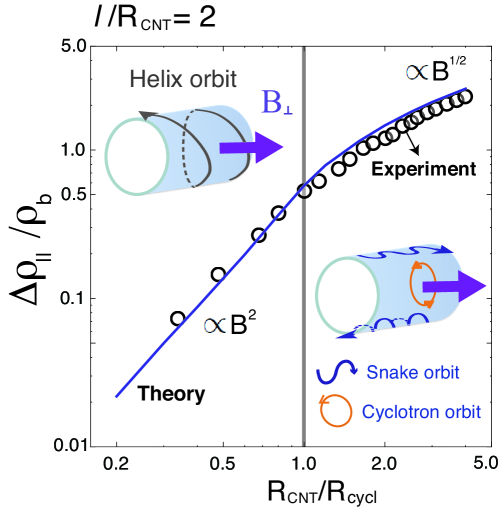
In the regime where the cyclotron radius is smaller than the behavior of the MR changes qualitatively. The MR indeed exhibits a much slower increase as testified by the slope change in Fig. 1. This is because the magnetic field is large enough to allow for the formation of usual cyclotron orbits localized in the regions of the CNT where the surface normal is parallel to the transversal magnetic field direction 23, 24, which do not contribute to the MR. The latter is indeed entirely set by the contribution of the snake orbits appearing close to the boundaries where the normal component of the magnetic field switches its sign 25. As we explicitly prove in the Supporting Information, the snake state contribution to the MR is with a proportionality factor that is independent of the mean free path value in the regime . This sublinear power-law dependence of the MR for sufficiently large magnetic fields is in between the saturation 26, 27 and the linear growth 28, 29, 30 encountered in other material systems.
To verify the validity of our approach, we have compared our theoretical results with the MR measurements performed by Kasumov and collaborators 21 on a nm outer radius isolated MWCNT, which show an inflexion point in the MR at an external moderate magnetic field of T. From the condition that the inflexion point occurs when the CNT radius exactly matches the effective cyclotron radius, we obtain m kg/s, which is compatible with a Fermi velocity 31, 32 of the order of m/s and a cyclotron mass approximatively two order of magnitudes smaller than the mass of free carriers. By further taking into account a sizable magnetic-field independent resistivity, which we attribute to inter-wall and contact resistivities suppressing the MR by approximatively one order of magnitude, we find a perfect agreement in the behavior of the MR as a function of the magnetic-field strength [see Fig. 1]. Moreover, the value of the mean free path nm is consistent with the experimental values reported in high-biased SWCNT 33.
Having established that our analysis in the classical diffusive transport regime correctly accounts for the behavior of the MR in CNTs up to moderate magnetic field strengths, we now move to analyze the magnetotransport properties of CNSs taking into account their peculiar geometric structure. The fact that the characteristic radii of the scrolls are comparable to the electronic mean free path – they generally lie in the tens of nanometer scale – implies that the electronic transport is in the quasi-ballistic regime 34 where impurity scattering and boundary scattering at the inner and outer radius of the scroll are of equal importance. For the latter, we will assume fully diffusive scattering 35, 36 and set the specularity parameter to zero.
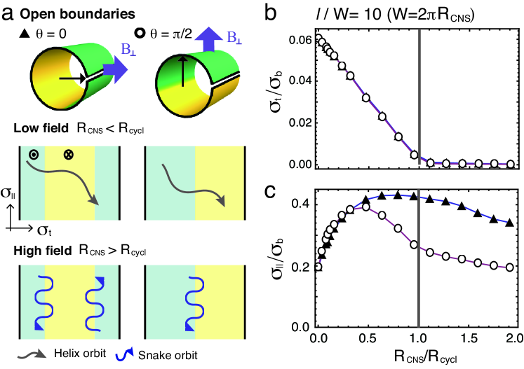
In CNSs the adjacent graphene layers typically have incommensurate lattice structures. Therefore interlayer electron tunneling becomes negligible 13 even though the separation between the overlapping regions is about the same as in graphite, nm. This also implies that we can again switch to an equivalent two-dimensional description and analyze the magnetotransport properties of a 2D channel of total width subject to a periodic magnetic field with functional form . Here the angle indicates the direction of the transversal magnetic field with respect to the inner edge of the scroll with . The outer edge of the CNS is defined by with indicating the number of the CNS turns which is treated, for convenience, as a continuous variable 37. In the remainder we will restrict ourselves to a one-winding CNS with . We emphasize that the presence of overlapping fringes in CNSs generally yields a noninteger value . This, however, does not qualitatively change the main features of the electronic transport, which are entirely set by the presence, and not the precise location, of the open boundaries in a CNS.
We can explicitly monitor the effect of boundary scattering on the magnetoconductivity by modifying Eq. 1 as follows
| (2) |
where is the transit time for a carrier with given initial position to reach the boundary 38, 39. Fig. 2(b) shows the magnetic field dependence of the conductivity along the CNS azimuthal direction measured in units of the conventional conductivity of a “bulk” () 2D channel in zero magnetic field. Here, we have set the mean free path to be one order of magnitude larger than the CNS width to assure the transport is well inside the quasi-ballistic regime. For zero magnetic field diffusive boundary scattering strongly suppresses the conductivity along the CNS width. A finite magnetic field leads to a further decrease of the conductivity, independent on the direction of the transversal magnetic field. The behavior of the conductivity component along the CNS axis is instead entirely different [see Fig. 2(c)]. In the weak-field regime we find an enhancement of the conductivity due to magnetic reduction of backscattering 34. This enhancement of the conductivity is followed by an ultimate suppression due to the formation of snake orbits, which, as discussed above, yield a positive MR. Moreover, we find the conductivity to strongly depend on the magnetic field direction. This is because for a magnetic field oriented along the edge axis () there are two regions where its normal component switches sign [c.f. Fig. 2(a)], contrary to the case of a magnetic field oriented perpendicularly to the edge axis () in which case the magnetic field switch is encountered only along one line of the scroll. The ensuing proliferation of snake orbits for then leads to a much slower suppression of the conductivity since their contribution instead of the usual contribution of cyclotron orbits.
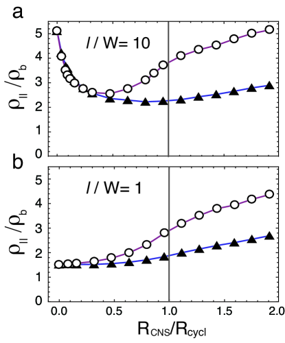
The knowledge of the magnetoconductivity tensor components allow us to obtain the behavior of the magnetoresistance . For , the zero-field resistivity is well described by the well-known formula 34 accounting for boundary scattering effects on the resistivity. In the weak-field regime a negative MR due to magnetic suppression of backscattering is explicitly manifest only when the mean free path largely exceeds the width of the CNS [c.f. Fig. 3], which is in perfect analogy with the situation encountered in a 2D channel subject to an homogeneous perpendicular magnetic field 40. In the intermediate field regime, the MR behavior strongly resembles the MR in the absence of boundary scattering [c.f. Fig. 1] but acquires a strong directional dependence independent of the ratio . As long as the boundary scattering is completely diffusive, the directional dependence comes entirely from the aforementioned proliferation of snake orbits for independent of the relative importance between internal impurity and boundary scattering.
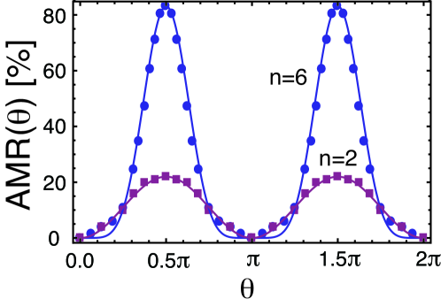
Fig. 4 shows the dependence of the magnetoresistance as a function of the external magnetic field direction. We find that the angular dependence of the magnetoresistance takes the functional form
| (3) |
with quantifying the magnitude of the anisotropic magnetoresistance (AMR) effect. In the weak field regime the angular dependence of the MR can be accurately described by the functional form of the AMR effect in bulk materials 16 given by in Eq. 3. Its magnitude is proportional to the strength of the externally applied magnetic field, and can be further increased under charge injection due to the CNS diameter increase 8. For sufficiently large magnetic field strengths, however, the increase of the resistance at becomes much more rapid with the angular dependence that can be described by Eq. 3 with . In this regime and independent of the ratio, the AMR reaches a giant value , which is comparable to the AMR magnitude observed in the quantum anomalous Hall phase of ferromagnetic topological insulator thin films15.
To wrap up, we have predicted, using a simple model of classical diffusion, a giant anisotropic magnetoresistance in carbon nanoscrolls subject to externally applied transversal magnetic fields. This phenomenon is entirely due to the formation of snake orbits yielding a positive magnetoresistance, whose number changes with the direction of the field. For moderate magnetic fields for which the effective cyclotron radius is smaller than the characteristic radius of the CNS we find an extremely large AMR with a magnitude up to . In the ballistic regime, snake states formed in ultraclean graphene junctions 41 have been shown to lead to conductance oscillations 42, 43. A similar phenomenon has been predicted to occur in low-density semiconducting core-shell nanowires subject to transversal magnetic fields44. Our calculations proves on solid grounds that the formation of snake orbits strongly impacts the classical diffusive transport properties as well. Therefore, our prediction can be tested not only in CNS but also in semiconducting curved nanostructures manufactured with the rolled-up nanotechnology 45.
Supporting Information
Classical electron orbits in tubular nanostructures subject to transversal magnetic fields, snake orbits contribution to the magnetoresistance, details of the angular dependence of the magnetoresistance. This material is available free of charge via the Internet at http://pubs.acs.org.
Notes
The authors declare no competing financial interests.
We acknowledge the financial support of the Future and Emerging Technologies (FET) programme within the Seventh Framework Programme for Research of the European Commission under FET-Open grant number: 618083 (CNTQC). C.O. acknowledges support from the Deutsche Forschungsgemeinschaft (Grant No. OR 404/1-1), and from a VIDI grant (Project 680-47-543) financed by the Netherlands Organization for Scientific Research (NWO). C-H. C. thanks Kun Peng Dou for helpful discussions.
References
- Dresselhaus et al. 2001 Dresselhaus, M. S.; Dresselhaus, G.; Avouris, P. Carbon Nanotubes: Synthesis, Structure, Properties, and Applications, 1st ed.; Springer-Verlag Berlin Heidelberg, 2001
- Geim and Novoselov 2007 Geim, A. K.; Novoselov, K. S. Nat. Mater. 2007, 6, 183–191
- Jariwala et al. 2013 Jariwala, D.; Sangwan, V. K.; Lauhon, L. J.; Marks, T. J.; Hersam, M. C. Chem. Soc. Rev. 2013, 42, 2824–2860
- Viculis et al. 2003 Viculis, L. M.; Mack, J. J.; Kaner, R. B. Science 2003, 299, 1361–1361
- Braga et al. 2004 Braga, S. F.; Coluci, V. R.; Legoas, S. B.; Giro, R.; Galvão, D. S.; Baughman, R. H. Nano Lett. 2004, 4, 881–884
- Bacon 1960 Bacon, R. J. Appl. Phys. 1960, 31, 283–290
- Xie et al. 2009 Xie, X.; Ju, L.; Feng, X.; Sun, Y.; Zhou, R.; Liu, K.; Fan, S.; Li, Q.; Jiang, K. Nano Lett. 2009, 9, 2565–2570
- Rurali et al. 2006 Rurali, R.; Coluci, V. R.; Galvão, D. S. Phys. Rev. B 2006, 74, 085414
- Shi et al. 2010 Shi, X.; Cheng, Y.; Pugno, N. M.; Gao, H. Appl. Phys. Lett. 2010, 96
- Chen et al. 2007 Chen, Y.; Lu, J.; Gao, Z. J. Phys. Chem. C 2007, 111, 1625–1630
- Pan et al. 2005 Pan, H.; Feng, Y.; Lin, J. Phys. Rev. B 2005, 72, 085415
- Li et al. 2012 Li, T.; Lin, M.; Huang, Y.; Lin, T. Phys. Lett. A 2012, 376, 515 – 520
- Cresti et al. 2012 Cresti, A.; Fogler, M. M.; Guinea, F.; Castro Neto, A. H.; Roche, S. Phys. Rev. Lett. 2012, 108, 166602
- Ferrari et al. 2008 Ferrari, G.; Bertoni, A.; Goldoni, G.; Molinari, E. Phys. Rev. B 2008, 78, 115326
- Kandala et al. 2015 Kandala, A.; Richardella, A.; Kempinger, S.; Liu, C.-X.; Samarth, N. Nat. Commun. 2015, 6, 7434
- McGuire and Potter 1975 McGuire, T.; Potter, R. IEEE Trans. Magn. 1975, 11, 1018–1038
- O’Handley 2000 O’Handley, R. C. Modern Magnetic Materials: Principles and Applications; Wiley: New York, 2000; p. 573
- Gopinhadan et al. 2015 Gopinhadan, K.; Shin, Y.; Jalil, R.; Venkatesan, T.; Geim, A.; Castro Neto, A.; Yang, H. Nat. Commun. 2015, 6, 9337
- Bhandari et al. 2016 Bhandari, S.; Lee, G.-H.; Klales, A.; Watanabe, K.; Taniguchi, T.; Heller, E.; Kim, P.; Westervelt, R. M. Nano Lett. 2016, 16, 1690–1694
- Song et al. 1994 Song, S. N.; Wang, X. K.; Chang, R. P. H.; Ketterson, J. B. Phys. Rev. Lett. 1994, 72, 697–700
- Kasumov et al. 1996 Kasumov, A. Y.; Khodos, I. I.; Ajayan, P. M.; Colliex, C. Europhys. Lett. 1996, 34, 429
- Noto and Tsuzuku 1975 Noto, K.; Tsuzuku, T. Jpn. J. Appl. Phys. 1975, 14, 46
- Chang et al. 2014 Chang, C.-H.; van den Brink, J.; Ortix, C. Phys. Rev. Lett. 2014, 113, 227205
- Chang and Ortix 2017 Chang, C.-H.; Ortix, C. Int. J. Mod. Phys. B 2017, 31, 1630016
- Müller 1992 Müller, J. E. Phys. Rev. Lett. 1992, 68, 385–388
- Brug et al. 1996 Brug, J. A.; Anthony, T. C.; Nickel, J. H. MRS Bull. 1996, 21, 23 27
- Gallego et al. 1994 Gallego, J. M.; Lederman, D.; Moran, T. J.; Schuller, I. K. Appl. Phys. Lett. 1994, 64, 2590–2592
- Friedman et al. 2010 Friedman, A. L.; Tedesco, J. L.; Campbell, P. M.; Culbertson, J. C.; Aifer, E.; Perkins, F. K.; Myers-Ward, R. L.; Hite, J. K.; Eddy, C. R.; Jernigan, G. G.; Gaskill, D. K. Nano Lett. 2010, 10, 3962–3965
- Wang et al. 2010 Wang, X.-L.; Dou, S. X.; Zhang, C. NPG Asia Mater. 2010, 2, 31–38
- Wang et al. 2012 Wang, X.; Du, Y.; Dou, S.; Zhang, C. Phys. Rev. Lett. 2012, 108, 266806
- Lemay et al. 2001 Lemay, S. G.; Janssen, J. W.; van den Hout, M.; Mooij, M.; Bronikowski, M. J.; Willis, P. A.; Smalley, R. E.; Kouwenhoven, L. P.; Dekker, C. Nature 2001, 412, 617–620
- Liang et al. 2001 Liang, W.; Bockrath, M.; Bozovic, D.; Hafner, J. H.; Tinkham, M.; Park, H. Nature 2001, 411, 665–669
- Park et al. 2004 Park, J.-Y.; Rosenblatt, S.; Yaish, Y.; Sazonova, V.; Üstü nel, H.; Braig, S.; Arias, T. A.; Brouwer, P. W.; McEuen, P. L. Nano Lett. 2004, 4, 517–520
- Beenakker and van Houten 1991 Beenakker, C. W. J.; van Houten, H. Solid State Phys. 1991, 44, 1–228
- Mayorov et al. 2011 Mayorov, A. S.; Gorbachev, R. V.; Morozov, S. V.; Britnell, L.; Jalil, R.; Ponomarenko, L. A.; Blake, P.; Novoselov, K. S.; Watanabe, K.; Taniguchi, T.; Geim, A. K. Nano Lett. 2011, 11, 2396–2399
- Masubuchi et al. 2012 Masubuchi, S.; Iguchi, K.; Yamaguchi, T.; Onuki, M.; Arai, M.; Watanabe, K.; Taniguchi, T.; Machida, T. Phys. Rev. Lett. 2012, 109, 036601
- Ortix and van den Brink 2010 Ortix, C.; van den Brink, J. Phys. Rev. B 2010, 81, 165419
- Li and Marsocci 1972 Li, T.-c.; Marsocci, V. A. Phys. Rev. B 1972, 6, 391–400
- Li and Marsocci 1972 Li, T.-C.; Marsocci, V. A. Thin Solid Films 1972, 12, 57 – 61
- Ditlefsen and Lothe 1966 Ditlefsen, E.; Lothe, J. Philos. Mag. 1966, 14, 759–773
- Williams and Marcus 2011 Williams, J. R.; Marcus, C. M. Phys. Rev. Lett. 2011, 107, 046602
- Rickhaus et al. 2015 Rickhaus, P.; Makk, P.; Liu, M.-H.; Tóvári, E.; Weiss, M.; Maurand, R.; Richter, K.; Schönenberger, C. Nat. Commun. 2015, 6, 6470
- Taychatanapat et al. 2015 Taychatanapat, T.; Tan, J. Y.; Yeo, Y.; Watanabe, K.; Taniguchi, T.; Özyilmaz, B. Nat. Commun. 2015, 6, 6093
- Rosdahl et al. 2015 Rosdahl, T. O.; Manolescu, A.; Gudmundsson, V. Nano Lett. 2015, 15, 254–258
- Schmidt and Eberl 2001 Schmidt, O. G.; Eberl, K. Nature 2001, 410, 168