Observation of oscillatory relaxation in the Sn-terminated surface of epitaxial rock-salt SnSe {111}fragments{111}\{111\} topological crystalline insulator

Wencan Jin These authors contribute equally to this work. Columbia University, New York, New York 10027, USA    Suresh Vishwanath These authors contribute equally to this work. Cornell University, Ithaca, New York 14853, USA    Jianpeng Liu Kavli Institute for Theoretical Physics, University of California, Santa Barbara, California 93106, USA    Lingyuan Kong Beijing National Laboratory for Condensed Matter Physics, and Institute of Physics, Chinese Academy of Sciences, Beijing 100190, China    Rui Lou Department of Physics, Renmin University of China, Beijing 100872, China    Zhongwei Dai University of New Hampshire, Durham, NH 03824, USA    Jerzy T. Sadowski Center for Functional Nanomaterials, Brookhaven National Laboratory, Upton, New York 11973, USA    Xinyu Liu University of Notre Dame, Notre Dame, Indiana 46556, USA    Huai-Hsun Lien Cornell University, Ithaca, New York 14853, USA    Alexander Chaney Cornell University, Ithaca, New York 14853, USA    Yimo Han Cornell University, Ithaca, New York 14853, USA    Micheal Cao Cornell University, Ithaca, New York 14853, USA    Junzhang Ma Beijing National Laboratory for Condensed Matter Physics, and Institute of Physics, Chinese Academy of Sciences, Beijing 100190, China    Tian Qian Beijing National Laboratory for Condensed Matter Physics, and Institute of Physics, Chinese Academy of Sciences, Beijing 100190, China    Jerry I. Dadap Columbia University, New York, New York 10027, USA    Shancai Wang Department of Physics, Renmin University of China, Beijing 100872, China    Malgorzata Dobrowolska University of Notre Dame, Notre Dame, Indiana 46556, USA    Jacek Furdyna University of Notre Dame, Notre Dame, Indiana 46556, USA    David A. Muller Cornell University, Ithaca, New York 14853, USA    Karsten Pohl University of New Hampshire, Durham, NH 03824, USA    Hong Ding Beijing National Laboratory for Condensed Matter Physics, and Institute of Physics, Chinese Academy of Sciences, Beijing 100190, China    Huili Grace Xing grace.xing@cornell.edu Cornell University, Ithaca, New York 14853, USA University of Notre Dame, Notre Dame, Indiana 46556, USA    Richard M. Osgood, Jr osgood@columbia.edu Columbia University, New York, New York 10027, USA
Abstract

Topological crystalline insulators have been recently predicted and observed in rock-salt structure SnSe {111}fragments{111}\{111\} thin films. Previous studies have suggested that the Se-terminated surface of this thin film with hydrogen passivation, has a reduced surface energy and is thus a preferred configuration. In this paper, synchrotron-based angle-resolved photoemission spectroscopy, along with density functional theory calculations, are used to demonstrate conclusively that a rock-salt SnSe {111}fragments{111}\{111\} thin film epitaxially-grown on \ceBi2Se3 has a stable Sn-terminated surface. These observations are supported by low energy electron diffraction (LEED) intensity-voltage measurements and dynamical LEED calculations, which further show that the Sn-terminated SnSe {111}fragments{111}\{111\} thin film has undergone a surface structural relaxation of the interlayer spacing between the Sn and Se atomic planes. In sharp contrast to the Se-terminated counterpart, the observed Dirac surface state in the Sn-terminated SnSe {111}fragments{111}\{111\} thin film is shown to yield a high Fermi velocity, 0.50×10⁶fragments0.501060.50\times 10^{6}m/s, which suggests a potential mechanism of engineering the Dirac surface state of topological materials by tuning the surface configuration.

I Introduction

Topological phases of matter have attracted much interest for condensed matter physics community. The initial focus and discovery in this area was topological insulators (TIs) hasan2010colloquium; moore2010birth; qi2011topological, in which time reversal symmetry gives rise to topologically protected, conducting surface states in insulating bulk crystals. Beyond TIs, the search for new types of topological materials has recently also been extended to other cases, in which the role of topological protection arises from other symmetries including particle-hole symmetry schnyder2008classification, magnetic translational symmetry mong2010antiferromagnetic, and crystalline symmetry fu2011topological. In the last class of topological materials, topologically nontrivial properties are protected by crystalline symmetry, and are thus called topological crystalline insulators (TCIs) fu2011topological. The TCI phase has been theoretically predicted and experimentally verified in narrow-gap IV-VI semiconductors: SnTe tanaka2012experimental; tanaka2013two; littlewood2010band; zhang2016arpes, \cePb_1-xSn_xSe polley2014observation and \cePb_1-xSn_xTe (x\geq0.25) xu2012observation; yan2014experimental; tanaka2013tunability; safaei2013topological; gyenis2013quasiparticle; dziawa2012topological with a rock-salt structure. In these materials, bulk-band gaps are located at the four equivalent L points of the face-centered-cubic (FCC) Brillouin zone (see Fig. 1(c)); in addition, the energy-level ordering of the conduction and valence bands at the L points is inverted hsieh2012topological. A remarkable signature of the TCI phase is the presence of surface states with an even number of gapless Dirac cones on the {001}fragments{001}\{001\}, {111}fragments{111}\{111\} surface Brillouin zone (SBZ), these states are protected by the mirror symmetry with respect to the {110}fragments{110}\{110\} plane hsieh2012topological; sun2013rocksalt; liu2013two.

Refer to caption
Figure 1: (a) Schematic of the lattice structure of rock-salt SnSe. (b) Layered rock-salt SnSe depicted along the {111}fragments{111}\{111\} direction. (c) The Brillouin zone of bulk rock-salt SnSe and its projected {111}fragments{111}\{111\} surface Brillouin zone. (d) Temperature dependent XRD of SnSe/\ceBi2Se3/GaAs acquired using Cu KαfragmentsK𝛼K_{\alpha} line. Black dashed box and line denote the diffraction peaks for SnSe {111}fragments{111}\{111\} and Se cap, respectively. (e) Raman spectra of GeS-type SnSe (blue), rock-salt SnSe (red), and \ceBi2Se3 (purple). The excitation wavelength is 488nm.

For topological materials, in general, the surface configuration is crucial for their Dirac surface states. In particular, tin monochalcogenide TCI is an important platform for investigating the correlation between Dirac surface states and its surface configuration. Since the surface states of TCIs are crystal-symmtry protected, they depend sensitively on the surface orientation. In particular, the {001}fragments{001}\{001\} surface states possess hybridized double-Dirac-cones in close vicinity to the X¯¯𝑋\bar{X} point of the {001}fragments{001}\{001\} SBZ, while the {111}fragments{111}\{111\} surface states possess four Dirac cones centered at the Γ¯andfragments¯Γand\bar{\Gamma}$̅and¯Mpointsofthefragmentspointsofthepointsofthe{111}SBZtanaka2013two.Inpreviousexperiments,thefragmentsSBZtanaka2013two.Inpreviousexperiments,theSBZ\cite[cite]{\@@bibref{Authors Phrase1YearPhrase2}{tanaka2013two}{\@@citephrase{(}}{\@@citephrase{)}}}.Inpreviousexperiments,the{001}surfacestateshavebeenmoreintensivelyinvestigatedbecausethefragmentssurfacestateshavebeenmoreintensivelyinvestigatedbecausethesurfacestateshavebeenmoreintensivelyinvestigatedbecausethe{001}surfaceisanaturalcleavageplaneofrocksaltIVVIsemiconductors.Incontrast,thefragmentssurfaceisanaturalcleavageplaneofrocksaltIVVIsemiconductors.Incontrast,thesurfaceisanaturalcleavageplaneofrock-saltIV-VIsemiconductors.Incontrast,the{111}surfaceisapolarsurface,whichistypicallydifficulttopreparebecauseofitsunstablestructurearisingfromthedivergenceoftheelectrostaticenergyalongpolardirection,i.e.,thewellknowpolar catastrophetasker1979stability; noguera2000polar.Thisphenomenonmaybeamelioratedbystructuralreconfigurationofthesurface,whichstronglydependsonthetypeofsurfacetermination.Untilnow,alimitedsurfaceterminationhasbeenemployedinfragmentssurfaceisapolarsurface,whichistypicallydifficulttopreparebecauseofitsunstablestructurearisingfromthedivergenceoftheelectrostaticenergyalongpolardirection,i.e.,thewellknowpolar catastrophetasker1979stability; noguera2000polar.Thisphenomenonmaybeamelioratedbystructuralreconfigurationofthesurface,whichstronglydependsonthetypeofsurfacetermination.Untilnow,alimitedsurfaceterminationhasbeenemployedinsurfaceisapolarsurface,whichistypicallydifficulttopreparebecauseofitsunstablestructurearisingfromthedivergenceoftheelectrostaticenergyalongpolardirection,i.e.,thewellknow\textit{polar catastrophe}\cite[cite]{\@@bibref{Authors Phrase1YearPhrase2}{tasker1979stability, noguera2000polar}{\@@citephrase{(}}{\@@citephrase{)}}}.Thisphenomenonmaybeamelioratedbystructuralreconfigurationofthesurface,whichstronglydependsonthetypeofsurfacetermination.Untilnow,alimitedsurfaceterminationhasbeenemployedin{111}surfaceofrocksaltTCI.Forexample,recentstudiesof\cePb1xSnxTehaveindicatedTeterminationofitsfragmentssurfaceofrocksaltTCI.Forexample,recentstudiesof\cePbfragments1xSn𝑥TehaveindicatedTeterminationofitssurfaceofrocksaltTCI.Forexample,recentstudiesof\ce{Pb_{1-x}Sn_{x}Te}haveindicatedTe-terminationofits{111}surfaceyan2014experimental.Veryrecently,TCIphaseinmetastableSnSefragmentssurfaceyan2014experimental.Veryrecently,TCIphaseinmetastableSnSesurface\cite[cite]{\@@bibref{Authors Phrase1YearPhrase2}{yan2014experimental}{\@@citephrase{(}}{\@@citephrase{)}}}.Veryrecently,TCIphaseinmetastableSnSe{111}thinfilmwithrocksaltstructure,hasbeenobservedandwasattributedtobeSeterminatedandhydrogenpassivatedusingfirstprinciplescalculationwang2015molecular.ThuspreviousexperimentshaveshownthestablityofanionterminatedTCIs,eitherwithTeorSe.Thecationterminatedsurface,i.e.,thetruncatedbulkSnterminatedsurface,however,waspredictedtobeunstable,and,asaresult,itundergoessurfacereconstructiontodiminishitssurfaceenergywang2014structural.DespiteitsgreatimportancetothefullunderstandingofthisfamilyofTCIsanditsroleinthedevelopmentofpotentialhighqualityTCIdevices,astablecationterminatedTCIhasnotyetbeendemonstrated.Inthepresentwork,wepresentclearevidenceofastable,truncatedbulkSnterminatedSnSefragmentsthinfilmwithrocksaltstructure,hasbeenobservedandwasattributedtobeSeterminatedandhydrogenpassivatedusingfirstprinciplescalculationwang2015molecular.ThuspreviousexperimentshaveshownthestablityofanionterminatedTCIs,eitherwithTeorSe.Thecationterminatedsurface,i.e.,thetruncatedbulkSnterminatedsurface,however,waspredictedtobeunstable,and,asaresult,itundergoessurfacereconstructiontodiminishitssurfaceenergywang2014structural.DespiteitsgreatimportancetothefullunderstandingofthisfamilyofTCIsanditsroleinthedevelopmentofpotentialhighqualityTCIdevices,astablecationterminatedTCIhasnotyetbeendemonstrated.Inthepresentwork,wepresentclearevidenceofastable,truncatedbulkSnterminatedSnSethinfilmwithrocksaltstructure,hasbeenobservedandwasattributedtobeSe-terminatedandhydrogenpassivatedusingfirst-principlescalculation\cite[cite]{\@@bibref{Authors Phrase1YearPhrase2}{wang2015molecular}{\@@citephrase{(}}{\@@citephrase{)}}}.Thuspreviousexperimentshaveshownthestablityofanion-terminatedTCIs,eitherwithTeorSe.Thecation-terminatedsurface,i.e.,thetruncated-bulkSn-terminatedsurface,however,waspredictedtobeunstable,and,asaresult,itundergoessurfacereconstructiontodiminishitssurfaceenergy\cite[cite]{\@@bibref{Authors Phrase1YearPhrase2}{wang2014structural}{\@@citephrase{(}}{\@@citephrase{)}}}.DespiteitsgreatimportancetothefullunderstandingofthisfamilyofTCIsanditsroleinthedevelopmentofpotentialhigh-qualityTCIdevices,astablecation-terminatedTCIhasnotyetbeendemonstrated.\\ \par Inthepresentwork,wepresentclearevidenceofastable,truncated-bulkSn-terminatedSnSe{111}TCI,usingacomprehensivebatteryofexperimentalandtheoreticaltests.WealsopresentthefirstdirectevidenceofoscillatorystructuralrelaxationofthetopatomiclayersofthisTCI.Thesurfacestructureofthesethinfilmsischaracterizedusingselectedarealowenergyelectrondiffraction(fragmentsTCI,usingacomprehensivebatteryofexperimentalandtheoreticaltests.WealsopresentthefirstdirectevidenceofoscillatorystructuralrelaxationofthetopatomiclayersofthisTCI.Thesurfacestructureofthesethinfilmsischaracterizedusingselectedarealowenergyelectrondiffraction(TCI,usingacomprehensivebatteryofexperimentalandtheoreticaltests.WealsopresentthefirstdirectevidenceofoscillatorystructuralrelaxationofthetopatomiclayersofthisTCI.Thesurfacestructureofthesethinfilmsischaracterizedusingselected-arealow-energyelectrondiffraction(μLEED).Inaddition,LEEDintensityvoltage(I-V)measurements,combinedwithdynamicalLEEDcalculations,showthatourSnSefragmentsLEED).Inaddition,LEEDintensityvoltage(I-V)measurements,combinedwithdynamicalLEEDcalculations,showthatourSnSe-LEED).Inaddition,LEEDintensity-voltage(\textit{I-V})measurements,combinedwithdynamicalLEEDcalculations,showthatourSnSe{111}thinfilmshaveaSnterminatedsurfacewithoutsurfacereconstruction.InsteadstructuralrelaxationoftheinterlayerspacingbetweentheSnandSeatomicplanesoccurs.OurangleresolvedphotoemissionspectroscopymeasurementdemonstratearobustsurfacestateatthefragmentsthinfilmshaveaSnterminatedsurfacewithoutsurfacereconstruction.InsteadstructuralrelaxationoftheinterlayerspacingbetweentheSnandSeatomicplanesoccurs.OurangleresolvedphotoemissionspectroscopymeasurementdemonstratearobustsurfacestateatthethinfilmshaveaSn-terminatedsurfacewithoutsurfacereconstruction.InsteadstructuralrelaxationoftheinterlayerspacingbetweentheSnandSeatomicplanesoccurs.Ourangle-resolvedphotoemissionspectroscopymeasurementdemonstratearobustsurfacestateatthe¯Γ$̅ point with a Dirac point located at similar-to\sim0.4eV below EFfragmentsE𝐹E_{F}. In addition, these measurements reveal a much higher Fermi velocity (vFfragmentsv𝐹v_{F}) in the Sn-terminated SnSe than for its Se-terminated counterpart. The measured bands of Sn-terminated SnSe {111}fragments{111}\{111\} are accurately reproduced by our first-principles calculations. Despite the fact that most topological material design focuses on composition polley2016observation; lou2015sudden, this work paves the possibility of obtaining a tunable Dirac point and Fermi velocity in TCI by modifying the surface termination; it also shows clearly one potential approach to manipulation of topologically nontrivial surface states by tuning the surface structure through choice of growth conditions or decapping conditions.

II Results and discussion

Refer to caption
Figure 2: (a) Core level photoemission spectrum acquired using 100eV incident photon energy. (b) ARPES bandmap (hνfragmentshνh\nu=25eV) along the M¯¯𝑀\bar{M}-Γ¯¯Γ\bar{\Gamma}-M¯¯𝑀\bar{M} high symmetry direction. (c) MDCs plot of the band dispersion shown in (b). Energy positions of the Fermi level and Dirac point are denoted as EFfragmentsE𝐹E_{F} and EDfragmentsE𝐷E_{D}, respectively. (d) Excerpts of the photon-energy-dependent (hνfragmentshνh\nu=22, 30 and 34eV) ARPES bandmaps. (e) MDCs peak positions (blue dots) and linear fitting (red dashed line).
Refer to caption
Figure 3: First-principles calculations of the band structure for (a) Sn-terminated and (b) Se-terminated SnSe {111}fragments{111}\{111\} thin film. (c) Average electrostatic energy of Sn-terminated (blue) and Se-terminated (red) SnSe thin film as a function of z𝑧z. Inset shows a magnification of the curves at the surface.

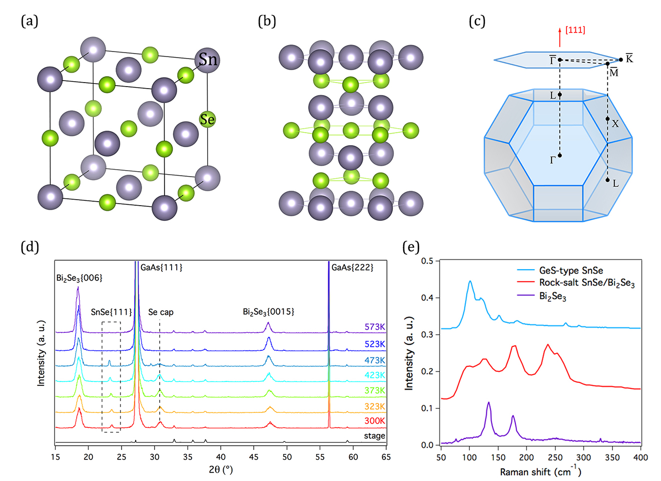
The Sn-Se system contains very rich phases. The energetically stable phase of SnSe has an orthorhombic GeS structure, which is a topologically trivial phase. Molecular beam epitaxy (MBE) is used to grow SnSe thin film in rock-salt structure (see Fig. 1(a)). This film has a thickness of 26 monolayers and is grown on a crystalline \ceBi2Se3 thin film on a GaAs {111}fragments{111}\{111\} substrate. The lattice constant of \ceBi2Se3 is closely matched to the in-plane lattice constant of rock-salt SnSe and, as a result, the epitaxial SnSe {111}fragments{111}\{111\} (see Fig. 1(b)) is constrained to a rock-salt structure. The growth conditions are detailed in the Methods section. The growth was carefully monitored and characterized in situ using reflection high-energy electron diffraction (RHEED) (see Supplementary Section I). The SnSe thin film is protected from ambient atomospheric exposure following growth with a Se cap in the growth chamber. Prior to our microscopy or spectroscopy measurements on each sample, the Se cap was removed by heating at 200 ° 200arcdegree200\text{\,}\mathrm{\SIUnitSymbolDegree}C for 30min in ultrahigh vacuum.

The crystalline structure of the epitaxially grown thin film was first investigated using temperature-dependent X-ray diffraction (XRD) from room temperature (RT) to 300 ° 300arcdegree300\text{\,}\mathrm{\SIUnitSymbolDegree}C (see Supplementary Section II for a discussion on off-axis XRD). The results, shown in Fig. 1(d), exhibit consistently well-defined peaks for GaAs {111}fragments{111}\{111\}, GaAs {222}fragments{222}\{222\}, \ceBi2Se3 {006}fragments{006}\{006\}, and \ceBi2Se3 {0015}fragments{0015}\{0015\}. In addition, well-defined peaks for SnSe {111}fragments{111}\{111\} and Se cap are seen. Note that in both on-axis and off-axis XRD measurements, no peak for orthorhombic SnSe is observed. Also, the Se cap peaks started to break down at 200 ° 200arcdegree200\text{\,}\mathrm{\SIUnitSymbolDegree}C, while the SnSe {111}fragments{111}\{111\} peaks slightly shifted due to thermal expansion and remained intact until 200 ° 200arcdegree200\text{\,}\mathrm{\SIUnitSymbolDegree}C. This result suggests that heating the sample at 200 ° 200arcdegree200\text{\,}\mathrm{\SIUnitSymbolDegree}C can successfully remove the Se cap without damaging the SnSe thin film. In addition, ancillary Raman spectra, which are shown in Fig. 1(e), support our supposition that this SnSe layer has a rock salt structure, which is clearly distinct from the structure of GeS-type SnSe. Finally, note that the well-resolved SnSe and \ceBi2Se3 peaks seen on the as-grown sample indicate that no significant intermixing during growth vishwanath2016controllable.

As mentioned above, there have been no reports of a direct measurement of the surface structure of rock-salt SnSe prior to the present work. Also, since rock-salt SnSe is a metastable phase, we found that transmission electron microscopy, which use high-energy electron beam bombardment of samples, triggered a transformation in SnSe and at the SnSe/Se cap interface (see Supplementary Section III). Similar electron-beam induced transformation in Sn-Se system was also reported recently in exfoliated \ceSnSe2 sutter2016electron. In order to establish this surface structure, measurements were carried out on our SnSe thin film using μ𝜇\mu-LEED and LEED I-V. The resulting SnSe μ𝜇\mu-LEED pattern shows one set of sharp hexagonal diffraction spots along with a faint ring-like background. This result is consistent with our thin films having one dominant in-plane crystal orientation along with a small percentage of randomly misaligned small domains. This observation allows us to rule out the (2×1fragments212\times 1) or 3×3fragments33\sqrt{3}\times\sqrt{3} R30 ° 30arcdegree30\text{\,}\mathrm{\SIUnitSymbolDegree} reconstruction wang2014structural.

Additional measurements were made of the sample surface (see Supplementary Sections IV and V). First of all, a measurement was made of any variation in the domains along the surface. The probing electron beam (5 µm 5fragmentsµm5\text{\,}\mathrm{\SIUnitSymbolMicro m} in diameter) was translated across the sample for several hundreds of micrometers. No obvious change in the μ𝜇\mu-LEED pattern was observed, indicating long-range domain uniformity of the thin film. Secondly, surface roughness was quantitatively characterized using variations in the local surface normal (see Supplementary Section III), and the result indicated that epitaxial SnSe and \ceBi2Se3 layers were atomically flat. Moreover, in order to enable acquisition of the μ𝜇\mu-LEED pattern of GaAs {111}fragments{111}\{111\} substrate, each of the epitaxial thin layers were successively removed in situ by heating the sample slowly to 400 ° 400arcdegree400\text{\,}\mathrm{\SIUnitSymbolDegree}C. The GaAs {111}fragments{111}\{111\} substrate was found to display a well-defined hexagonal diffraction pattern, which was used to provide a known reciprocal lattice template by assuming the known lattice constant of GaAs as 5.65 Å 5.65Å5.65\text{\,}\mathrm{\SIUnitSymbolAngstrom} kaminska1989structural. The in-plane lattice constant of SnSe thin film was then determined to be 4.28±plus-or-minus\pm0.03 Å 0.03Å0.03\text{\,}\mathrm{\SIUnitSymbolAngstrom} by using the reciprocal vector ratio extracted from our μ𝜇\mu-LEED patterns. This value for SnSe is 1%fragmentssimilar-to1percent\sim 1\% larger than the published measured value of 4.23 Å 4.23Å4.23\text{\,}\mathrm{\SIUnitSymbolAngstrom} mariano1967polymorphism, yet it is in good agreement with the structural optimized value in density functional theory (DFT) calculations sun2013rocksalt; wang2015molecular.
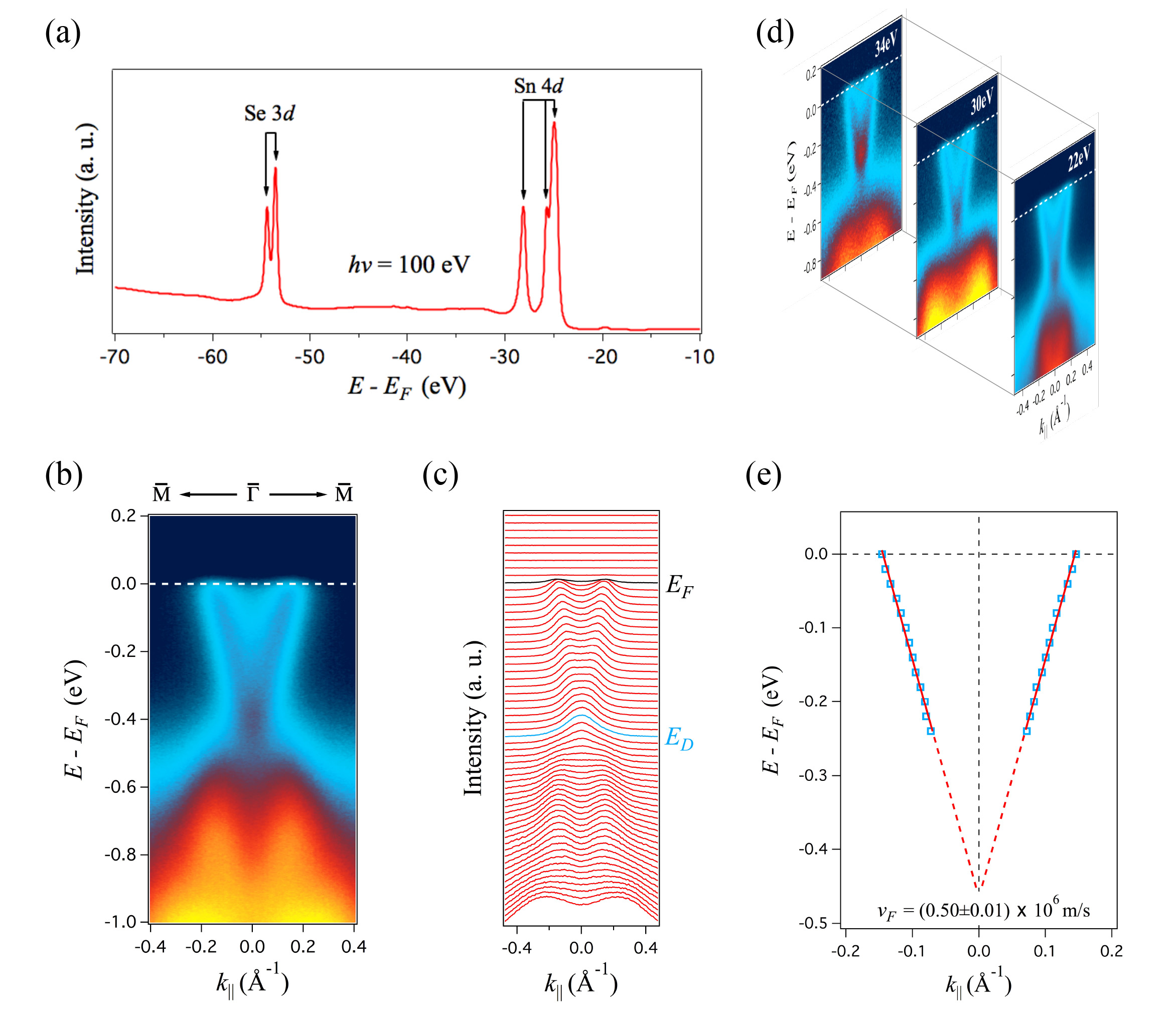
The electronic structure of the SnSe {111}fragments{111}\{111\} sample was directly measured using synchrotron-based high-resolution ARPES system. Figure 2(a) shows the integrated core-level photoemission spectrum of the sample. Well-defined Se 3d𝑑d and Sn 4d𝑑d spin-orbit doublets are immediately apparent in this figure. The peak at 28eV is assigned to a replica Sn 4d𝑑d state originating from the chemical shift of the Sn surface. (see Supplementary Section VI for a photoionization cross section analysis.) Note that since 26 layers of SnSe is much thicker than the penetration depth of the low energy photon, it is unlikely that the surface states of the \ceBi2Se3 buffer layer will be observed. Figure 2(b) shows the ARPES bandmap along the M¯¯𝑀\bar{M}-Γ¯¯Γ\bar{\Gamma}-M¯¯𝑀\bar{M} high-symmetry direction acquired using a 25eV incident photon energy. Figure 2(c) shows the momentum distribution curves (MDCs) plot of the bandmap of Fig. 2(b). In sharp contrast to the electronic structure of Se-terminated SnSe with hydrogen-passivation, where Dirac point at Γ¯pointislocatedatapproximately0.1eVbelowFermilevel(EF),weobservedDiraclikelineardispersivebandscrossingatfragments¯Γpointislocatedatapproximately0.1eVbelowFermilevel(fragmentsE𝐹),weobservedDiraclikelineardispersivebandscrossingat\bar{\Gamma}$̅pointislocatedatapproximately0.1eVbelowFermilevel(\textit{$E_{F}$}),weobservedDirac-likelineardispersivebandscrossingat0.4eVbelowEF.Inaddition,toverifythefragments0.4eVbelowfragmentsE𝐹.Inaddition,toverifythe0.4eVbelow\textit{$E_{F}$}.Inaddition,toverifythek_z((({111}directioninBZ)dispersionofthebandfeatures,photonenergydependentARPESmeasurementswerecarriedout(seeSupplementarySectionVIII).Figure2(d)showstheexcerptsfromthephotonenergydependence(hfragmentsdirectioninBZ)dispersionofthebandfeatures,photonenergydependentARPESmeasurementswerecarriedout(seeSupplementarySectionVIII).Figure2(d)showstheexcerptsfromthephotonenergydependence(hdirectioninBZ)dispersionofthebandfeatures,photon-energy-dependentARPESmeasurementswerecarriedout(seeSupplementarySectionVIII).Figure~{}\ref{fig:fig2}(d)showstheexcerptsfromthephoton-energy-dependence(hν=22,30and34eV)ARPESbandmap.TheDiraclikebandfeaturedoesnotshowanynoticeablechangewithvaryingincidentphotonenergyoverawideenergyrange,confirmingthatitisasurfacestate.However,thebandswithbindingenergyhigherthan0.5eVdoshowstronglyphotonenergydependentevolution,indicatingtheirbulkorigin.AsshowninFig.2(e),linearfittingtotheMDCpeaksyieldsaFermiwavevectoroffragments22,30and34eV)ARPESbandmap.TheDiraclikebandfeaturedoesnotshowanynoticeablechangewithvaryingincidentphotonenergyoverawideenergyrange,confirmingthatitisasurfacestate.However,thebandswithbindingenergyhigherthan0.5eVdoshowstronglyphotonenergydependentevolution,indicatingtheirbulkorigin.AsshowninFig.2(e),linearfittingtotheMDCpeaksyieldsaFermiwavevectorof=22,30and34eV)ARPESbandmap.TheDirac-likebandfeaturedoesnotshowanynoticeablechangewithvaryingincidentphotonenergyoverawideenergyrange,confirmingthatitisasurfacestate.However,thebandswithbindingenergyhigherthan0.5eVdoshowstronglyphoton-energy-dependentevolution,indicatingtheirbulkorigin.AsshowninFig.~{}\ref{fig:fig2}(e),linearfittingtotheMDCpeaksyieldsaFermiwavevectorofk_F=0.14fragments0.14=0.14±0.01 Å1andahighFermivelocityoffragments 0.01Åfragments1andahighFermivelocityof$0.01\text{\,}{\mathrm{\SIUnitSymbolAngstrom}}^{-1}$andahighFermivelocityofv_F=(0.50fragments(0.50=(0.50±0.01)fragments0.01)0.01)×10^6m/s.TheFermivelocityforSnterminatedSnSesampleisthreetimeslargerthanforitsSeterminatedcounterpart.Toaidininterpretingtheelectronicstructureandtopologicalcharacter,firstprinciplescalculationswerecarriedout(seeMethodssectionforcalculationdetails).IncontrasttothemethodreportedinRef.wang2015molecular,inwhichdanglingbondswereeliminatedusinghydrogenpassivationoftheSetermination,atruncatedbulksurfacewasusedinourcalculations.Infactinourcalculation,theSnterminatedsurface(seeFig.3(a))andSeterminatedsurface(seeFig.3(b))arefoundtoyieldstrikinglydifferentsurfacestates.IntheSnterminatedcase,theDiracpointisclosetothebulkvalenceband,whileintheSeterminatedcase,theDiracpointisclosetothebulkconductionband.ThisresultimpliesthatourSnSefragmentsms.TheFermivelocityforSnterminatedSnSesampleisthreetimeslargerthanforitsSeterminatedcounterpart.Toaidininterpretingtheelectronicstructureandtopologicalcharacter,firstprinciplescalculationswerecarriedout(seeMethodssectionforcalculationdetails).IncontrasttothemethodreportedinRef.wang2015molecular,inwhichdanglingbondswereeliminatedusinghydrogenpassivationoftheSetermination,atruncatedbulksurfacewasusedinourcalculations.Infactinourcalculation,theSnterminatedsurface(seeFig.3(a))andSeterminatedsurface(seeFig.3(b))arefoundtoyieldstrikinglydifferentsurfacestates.IntheSnterminatedcase,theDiracpointisclosetothebulkvalenceband,whileintheSeterminatedcase,theDiracpointisclosetothebulkconductionband.ThisresultimpliesthatourSnSem/s.TheFermivelocityforSn-terminatedSnSesampleisthreetimeslargerthanforitsSe-terminatedcounterpart.\\ \par Toaidininterpretingtheelectronicstructureandtopologicalcharacter,first-principlescalculationswerecarriedout(see\textbf{Methods}sectionforcalculationdetails).IncontrasttothemethodreportedinRef.\cite[cite]{\@@bibref{Authors Phrase1YearPhrase2}{wang2015molecular}{\@@citephrase{(}}{\@@citephrase{)}}},inwhichdanglingbondswereeliminatedusinghydrogen-passivationoftheSe-termination,atruncated-bulksurfacewasusedinourcalculations.Infactinourcalculation,theSn-terminatedsurface(seeFig.~{}\ref{fig:fig3}(a))andSe-terminatedsurface(seeFig.~{}\ref{fig:fig3}(b))arefoundtoyieldstrikinglydifferentsurfacestates.IntheSn-terminatedcase,theDiracpointisclosetothebulkvalenceband,whileintheSe-terminatedcase,theDiracpointisclosetothebulkconductionband.ThisresultimpliesthatourSnSe{111}thinfilmhasaSnterminatedsurface.Infact,alinearfittingtothecalculatedsurfacestateoftheSnterminatedSnSeyieldsaFermivelocityof0.55fragmentsthinfilmhasaSnterminatedsurface.Infact,alinearfittingtothecalculatedsurfacestateoftheSnterminatedSnSeyieldsaFermivelocityof0.55thinfilmhasaSn-terminatedsurface.Infact,alinearfittingtothecalculatedsurfacestateoftheSn-terminatedSnSeyieldsaFermivelocityof0.55×10^6m/s,whichisingoodagreementwithourmeasuredvalue.ThephysicaloriginoftheDiracpointshiftisattributedtothedifferentelectrostaticenergyofthesetwosurfaces.Inparticular,thisfragmentsms,whichisingoodagreementwithourmeasuredvalue.ThephysicaloriginoftheDiracpointshiftisattributedtothedifferentelectrostaticenergyofthesetwosurfaces.Inparticular,thism/s,whichisingoodagreementwithourmeasuredvalue.ThephysicaloriginoftheDiracpointshiftisattributedtothedifferentelectrostaticenergyofthesetwosurfaces.Inparticular,thiszdependentaverageelectrostaticenergyisobtainedusingtheformula:fragmentsdependentaverageelectrostaticenergyisobtainedusingtheformula:-dependentaverageelectrostaticenergyisobtainedusingtheformula:\\ \par¯V(z)=1cA∫_z+c/2^z-c/2dz∫∫_AdxdyV(x,y,z)wherefragmentswhere\par whereV(x,y,z)isthemicroscopicelectrostaticenergy,fragmentsisthemicroscopicelectrostaticenergy,isthemicroscopicelectrostaticenergy,cisthelatticeconstantinthefragmentsisthelatticeconstantintheisthelatticeconstantinthezdirection(fragmentsdirection(direction(zisthenormalofSnSefragmentsisthenormalofSnSeisthenormalofSnSe{111}surface),andfragmentssurface),andsurface),andAistheareaoftheunitcellinxyplane.Theblue(red)curveinFig.3(c)istheaverageelectrostaticenergyfragmentsistheareaoftheunitcellinxyplane.Theblue(red)curveinFig.3(c)istheaverageelectrostaticenergyistheareaoftheunitcellinx-yplane.Theblue(red)curveinFig.~{}\ref{fig:fig3}(c)istheaverageelectrostaticenergy¯V(z)fortheSnterminated(Seterminated)slab.Eventhoughfragments(z)fortheSnterminated(Seterminated)slab.Eventhough(z)fortheSn-terminated(Se-terminated)slab.Eventhough¯V(z)oftheSeterminatedslabislowerthanthatoftheSnterminatedslabinthebulkregion,theelectrostaticenergyincreasesrapidlyatthesurface.AsshownintheinsetofFig.3(c),atthesurfaceindicatedbytheverticalgrayline,fragments(z)oftheSeterminatedslabislowerthanthatoftheSnterminatedslabinthebulkregion,theelectrostaticenergyincreasesrapidlyatthesurface.AsshownintheinsetofFig.3(c),atthesurfaceindicatedbytheverticalgrayline,(z)oftheSe-terminatedslabislowerthanthatoftheSn-terminatedslabinthebulkregion,theelectrostaticenergyincreasesrapidlyatthesurface.AsshownintheinsetofFig.~{}\ref{fig:fig3}(c),atthesurfaceindicatedbytheverticalgrayline,¯V(z)oftheSnterminatedslabislowerthanthatoftheSeterminatedslabbyfragments(z)oftheSnterminatedslabislowerthanthatoftheSeterminatedslabby(z)oftheSn-terminatedslabislowerthanthatoftheSe-terminatedslabby0.4eV,whichisconsistentwithourARPESdataandfirstprinciplescalculations.Figure 4Figure 44Figure 44CalculatedLEEDI-Vcurvesforthe(00)diffractionbeamforanoptimizedSn-terminatefragments0.4eV,whichisconsistentwithourARPESdataandfirstprinciplescalculations.Figure 4Figure 44Figure 44CalculatedLEEDI-Vcurvesforthe(00)diffractionbeamforanoptimizedSn-terminate

Conversion to HTML had a Fatal error and exited abruptly. This document may be truncated or damaged.