Slow light in saturable absorbers: Progress in the resolution of a controversy
Abstract
There are two opposing models in the analysis of the slow transmission of light pulses through saturable absorbers. The canonical incoherent bleaching model simply explains the slow transmission by combined effects of saturation and of non-instantaneous response of the medium resulting in absorption of the front part of the incident pulse larger than that of its rear. The second model, referred to as the coherent-population-oscillations (CPO) model, considers light beams whose intensity is slightly pulse modulated and attributes the time delay of the transmitted pulse to a reduction of the group velocity. We point out some inconsistencies in the CPO model and show that the two models lie in reality on the same hypotheses, the equations derived in the duly rectified CPO model being local expressions of the integral equations obtained in the incoherent bleaching model. When intense pulses without background are used, the CPO model, based on linearized equations, breaks down. The incoherent bleaching model then predicts that the transmitted light should vanish when the intensity of the incident light is strictly zero. This point is confirmed by the experiments that we have performed on ruby with square-wave incident pulses and we show that the whole shape of the observed pulses agrees with that derived analytically by means of the incoherent bleaching model. We also determine in this model the corresponding evolution of the fluorescence light, which seems to have been evidenced in other experiments.
pacs:
42.25.Bs, 42.25.Lc, 42.50.MI Introduction
The group velocity is a basic concept in the study of the propagation of coherent light pulses of slowly varying amplitude in a linear, time independent, dispersive medium. It is invariably introduced in every review on slow and fast light (see, e.g., bo02 ; bo09 ). Expressing that the phase of the optical field is stationary at the frequency of the pulse carrier, it is given without any ambiguity by the relation :
| (1) |
where is the light velocity in vacuum, designates the refractive index at the optical frequency and is a short-hand notation of its derivative for . Slow light is obtained when takes large positive values (steep dispersion), the group velocity being then much smaller than the corresponding phase velocity . As a consequence of the Kramers-Kronig relations, this occurs in particular when the carrier frequency of the light pulses is close to the frequency of a well-marked maximum of the medium transmission (minimum of absorption). When , the group velocity is minimal and a simple application of the moment theorem shows that the center of gravity of the pulse envelope then exactly propagates at the corresponding group velocity whatever the pulse shape is ma03 . It should be mentioned that, due to the unavoidable distortion of a pulse propagating in a dispersive absorptive medium, the location of its maximum generally differs from that of its center of gravity. It has been however demonstrated that, under certain general conditions, the transmitted pulse becomes nearly Gaussian for large enough propagation distances, with obviously ma06 .
An important issue for eventual applications of slow light is the fractional delay / , where is the full width at half-maximum (FWHM) of the intensity profile of the incident pulse. Large fractional delays (up to 25 with moderate pulse attenuation) have been evidenced when the required peak in the medium transmission is associated with the minimum of absorption occurring half-way between two absorption lines ta03 ; ca06 ; ca07 . Most often, the transmission peak is obtained by applying an extra coherent wave interacting nonlinearly with the medium, exploiting for instance electromagnetically induced transparency (EIT) in atomic vapors ka95 or Brillouin-induced gain in optical fibers so05 . Slow light becomes a fashionable topic with the demonstration in an EIT experiment of a group velocity as slow as in an ultra-cold atomic gas ha99 . Subsequently the experiments showing delays in the transmission of light pulses were systematically analyzed in terms of slow group velocity. Such an analysis, indisputable for the EIT experiments, is, however, questionable in the cases where the group velocity as given by Eq.(1) is not well defined al06 .
We specifically examine here the case of the transmission of light pulses through saturable absorbers. As far back as 1965, Gires and Combaud gi65 showed that the stationary transmission of organic dyes is fairly well reproduced by assimilating the medium to a resonant two-level medium and using the rate equations approximation. By this means they obtained two equations coupling the population difference and the beam intensity. Solving these equations in the time-dependent case, Selden theoretically studied the transmission of light pulses, demonstrating narrowing, skewing, and time delay of the transmitted pulse se67 ; se70 in agreement with the experimental observations kh67 ; he68 ; se69 . From a qualitative viewpoint, the delay is thus interpreted in terms of pulse reshaping, the leading edge of the incident pulse being more attenuated than its trailing edge. Insofar as only the intensity is involved in the process, the phenomenon is currently referred to as incoherent bleaching to distinguish it from the pulse delay and reshaping that occur in purely coherent cases. Smith and Allen showed that delays sometimes attributed to self-induced transparency (a coherent phenomenon) are in fact the result of incoherent bleaching and are well reproduced by Selden’s theory sm73 . For a complete analysis of this point, see al87 . Always by using the incoherent bleaching model, Selden also examined the transmission of a continuous wave (cw) whose intensity is slightly modulated by a sine wave se71 . He showed that the intensity modulation index increases with the propagation distance whereas its phase is time delayed. These phenomena were observed on a ruby crystal at room temperature by Hillmann et al. hi83 and by Bigelow et al. bi03 . The latter, not taking into account the results of the incoherent bleaching model and considering the time delay of the modulation phase to be a group delay, claimed to have discovered “a new method that produces slow propagation of light” bi03 . Their theoretical analysis was based on an extrapolation of the results obtained when two separated coherent waves originate coherent oscillations of the populations at their frequency difference. Abundantly cited, Ref. bi03 paved the way to numerous articles invoking slow light based on coherent population oscillations (CPO). The systems under consideration are very various, comprising in particular doped crystals bi04 ; ba05 ; bi06 , semi-conductor devices ku04 ; va05 ; mo05 ; su06 ; ku07 , doped optical fibers sc06 ; ar10 ; be10 ; ja15 and doped glass microspheres hu16 . However, as shown in al06 ; za06 ; ma08 ; se09 , the effects reported in most of these articles do not involve coherence in the optical sense and can be explained in the frame of the incoherent bleaching model. The controversy on this matter restarted more recently with the publication of an article reporting experiments performed with a spinning ruby window wi13 . In this article Wisniewski-Barker et al. claim that their results are “incompatible with slow-light models based on simple pulse-reshaping arising from optical bleaching. ”This statement was contested by Kozlov et al. ko14 who performed an experiment validating the incoherent bleaching model but, surprisingly enough, Wisniewski-Barker et al. obtained the opposite result by using practically the same experimental setup wi14 . The controversy between the two models thus remains open. We attempt in the following to solve this issue. In Sec. II, we revisit the case of weak modulation depths by extending the results given in se71 ; ma08 and showing that, after correction, the CPO equations are simply local expressions of the integral equations obtained in the incoherent bleaching model. In Sec. III, we examine the validity of the bleaching model in the case of saturating pulses without background, we report experiments confirming the positive result of Kozlov et al. and we give a possible explanation of the different result reported in wi14 . We finally conclude in Sec. IV by summarizing and discussing our main results.
II Case of weak modulation depths
The CPO model traces back to the paper of Schwarz and Tan who studied how the absorption of a coherent probe wave by a saturable absorber is modified when the medium is submitted to a coherent saturating wave sc67 . They showed that the probe absorption spectrum then displays a dip (hole) centered at the pump frequency and of width , where is the population relaxation time. This dip is considered in hi83 as resulting from the population oscillations created in the medium by the beating of the pump and probe waves. When the directions of propagation of the two waves are different, it is possible to determine without ambiguity the absorption coefficient, the refractive index, and the group velocity of the probe wave. An experiment corresponding to this scheme has been performed by Ku et al., the slow group velocity being inferred from a measurement of the phase of the probe field ku04 . A related experiment involving counter-propagative waves is reported in ja15 .
The problems arise when the previous results are extended to the study of a single cw whose intensity is slightly modulated by a sine wave of low frequency. Denoting the modulation frequency, the modulated wave can be considered as the superimposition of three co-propagative cws, a saturating wave of frequency and two sidebands of frequency , acting as probes re1 . Bigelow et al. consider in bi03 that the two probes act independently but, as soundly noted by Sargent, “although neither probe frequency could influence the other on its own, they succeed in doing so with the help of the saturating wave” sa78 . This indicates that Eq. (9) in bi03 is not correct. This error has been pointed out for the first time by Mørk et al. mo05 who indicated that a correct application of the four-wave mixing theory leads to multiply the phase lag of the modulation and thus the corresponding time delay by a factor two.
Another point raised by Zapasskii and Kozlov za06 is that the CPO model implicitly assumes that the saturating wave has a spectral width much smaller than that of the hole induced in the absorption spectrum (). This condition is far from being met in most of the experiments. There is then no dip in the optical absorption spectrum and thus no associated slow light in the usual sense. In response to this objection, Piredda and Boyd pi07 , while continuing to invoke CPO, developed a model based on two equations coupling wave intensity and ground state population identical to those coupling wave intensity and population difference in the incoherent bleaching model gi65 ; se67 ; ma08 . They can be written in the simplified form
| (2) |
| (3) |
where is the ground-state recovery time, is the ground-state population normalized to its value at equilibrium, is the time retarded by the propagation time in the host medium (negligible compared to the delays considered in the following), is the beam intensity normalized to the saturation intensity, is the abscissa along the direction of propagation, and is the unsaturated absorption coefficient. Equations (2) and (3) implicitly assume that the ground state has no resolved structure. This condition is met in saturable absorbers which are dense media working at room temperature. It prevents oscillations at the frequency of a transition between two separated sublevels as evidenced in an alkali-metal vapor in buffer gas go02 ; re3 . In the case of a cw, Eqs (2) and (3) are reduced to
| (4) |
| (5) |
| (6) |
where, as in the following, upper bars refer to time-independent quantities. When the cw is slightly modulated, )= with and )= with . Making a calculation at the first order in and , taking into account Eqs.(4) and (6) and passing in the Fourier space pa87 , we obtain the transfer functions relating the Fourier transform of to that of and relating the Fourier transform of to . They read
| (7) |
| (8) |
The transfer function has a single pole and a single zero, both purely imaginary with a positive imaginary part. This implies that its inverse Fourier transform, that is the system impulse response, is real and that the system is causal with minimum phase shift pa87 . The phase of then obeys to the relation
| (9) |
where designates the Hilbert transform. Equation (9) may be considered as a generalized Kramers-Kronig relation. Similar properties hold for . We incidentally remark that is the transfer function of a simple electric network involving an RC circuit, two voltage dividers, and a voltage adder whereas an RC circuit and one voltage divider suffice to reproduce .
To relate Eq. (7) to the results given by Piredda and Boyd in pi07 , we consider the transfer function of the infinitely thin slice comprised between and in the medium. Taking into account Eq.(5), we obtain:
| (10) |
with
| (11) |
| (12) |
In relation with Eq. (9), we note that . When the modulation is reduced to a sine wave of frequency (as considered in most experiments), is the attenuation coefficient of the modulation and is the associated phase lag per length unit. Equations.(11) and (12) are strictly equivalent to those obtained in pi07 by invoking the CPO model and this shows that the CPO model does not bring new results with regard to the incoherent bleaching model. As expected, the phase lag is two times that given in bi03 ; re2 . A phase velocity can be associated with this phase lag. Depending on , this velocity should not be confused with a group velocity as it is made in bi03 ; pi07 . When the modulation consists in a pulse, the modulation group delay through the slice is derived from by the moment theorem. The slice being assumed to be infinitely thin and can be identified to the coefficient of the first degree term in the expansion of in power series of . We get
| (13) |
and the corresponding (local) group velocity reads:
| (14) |
Note that this group velocity is related to the intensity modulation transmission and should be distinguished from the group velocity as defined by Eq.(1) for pulses of coherent light.
The attenuation of the cw and of the modulation being intrinsically coupled, the widespread approximation consisting in neglecting the former to study the latter is not justified. The medium being assumed to occupy the space , the use of the integral expressions of Eq.(7,8) has the advantage to give directly and without requiring integration in . The corresponding expressions of and read
| (15) |
| (16) |
where designates inverse Fourier transforms. General characteristics of and can be derived by exploiting the remarkable properties of the cumulants do03 ; ma06 . The cumulants of the Fourier transform of a real function are given by the expansion
| (17) |
where the cumulants , and can be shown to be respectively equal to the mean time of , its variance , and its third centered moment . For , we get , and where is a short hand notation of . When the modulation is pulsed, the additivity property of the cumulants enables us to identify to the time delay of the pulse center-of-gravity (modulation group delay), to the increase of the pulse variance, and to that of . The group delay for the whole medium thus reads
| (18) |
We incidentally remark that this result can be retrieved by an integration combining Eqs.(13) and (5). An important point is that the group delay cannot exceed as large as the medium thickness may be. This limit is attained when (strongly saturating incident cw) and (medium nearly opaque). The variance and the third moment of the transmitted pulse are then also the largest. If the incident pulse is symmetric, the large positive value of entails that the output pulse will be strongly skew with a rise much steeper than its fall and, consequently, a time delay of its maximum much shorter than the group delay . See, for illustration, Fig.2(c) in ma08 . In the more realistic case where [always with ], the pulse distortion will be moderate but the group delay will be short compared to (while keeping significantly longer than ). When the incident pulse is a Gaussian of the form , the transmitted pulse derived from Eq.(15) reads
| (19) |
where erf designates the error function. Figure 1 shows the result obtained in the conditions of the experiment on ruby reported in bi06 . The parameters are , , , and , from which we deduce , , and (actually much shorter than ).
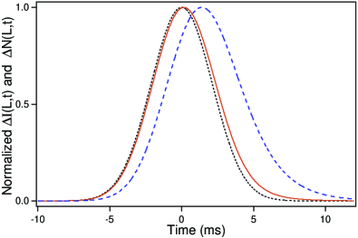
The incident pulse (dotted line) has a FWHM duration . As predicted, is significantly shorter than ( ) . We also compare in Fig. 1 to . It is easily deduced from Eq.(8) that the group delay of exceeds that of by a quantity
| (20) |
An important point is that this extra delay of the population evolution is much longer than the delay of the signal .

Coming back to the latter, Fig. 2 shows how the fractional delay of the transmitted pulse and the ratio depend on the duration of the incident pulse. It appears that approaches its asymptotic value for values of at which the fractional delay tends to 0 and, conversely, that the latter attains its maximum for a pulse duration such that is only about .
III Case of intense pulses without background
Even duly rectified, the CPO model, based on linearized equations, does not apply to the case of saturating pulses without background. In order to extend its range of application to such situations, its defenders invoke a mechanism of “self-pumping”, one part of the pulse acting as a pump whereas the remaining part acts as the probe bi03 ; wi14 . Without any quantitative support, this claim seems purely incantatory. It is even qualitatively incompatible with the fact that smooth symmetric pulses are broadened and gain a positive skewness (rise steeper than the fall) when they are superimposed on a large background (range of validity of the CPO model) whereas saturating pulses without background are narrowed and gain a negative skewness (fall steeper than the rise) se67 ; kh67 ; ma08 . Reporting experiments performed with a spinning ruby window, Wisniewski-Barker et al. wi13 recently proclaimed the failure of the incoherent bleaching model for this reference material. According to the demonstration made in the previous section of the equivalence of the two models, all the results obtained by means of the CPO model in the weak modulation limit would then require revision. Fortunately enough, it is nothing of the sort. The argument given in wi13 against the incoherent bleaching model is that, in this model, the transmitted light intensity should vanish when the incident light intensity is null, a condition that would be not verified in the experiments. In a comment, Kozlov et al. ko14 contested the achievement of strictly null incident intensity in these experiments and proposed a more drastic test where the incident beam is switched on-off by a mechanical chopper (100% square wave modulation). Performing this experiment, they obtained results validating the incoherent bleaching model, without the slightest transmitted intensity after the switching off of the incident beam. This however did not close the debate. Indeed, accepting the challenge proposed by Kozlov et al., Wisniewski-Barker et al. wi14 performed a nearly identical experiment. They obtained opposite results, evidencing in particular an exponential decrease of the transmitted intensity after the switching off of the incident beam. Note that they did not attempt to explain the discrepancy between their results and those of Kozlov et al. To solve this issue, we describe in the following an experiment that validates the incoherent bleaching model and theoretically determine in this model the time dependence of and of , providing a possible explanation of the experimental results obtained in wi14 .
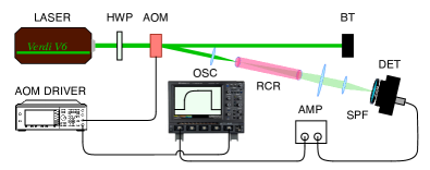
Figure 3 shows our experimental setup. It is very similar to those used in ko14 ; wi14 . We use a single longitudinal mode Nd:YVO4 laser (Verdi V6, Coherent) operating at as a cw source of controllable power. The laser beam is collimated and sent on an acousto-optic modulator (AA Opto-Electronic, MTS110-A-VIS). The light polarization at the input of the modulator is adjusted by a half-wave plate. A sine wave, at a 110 MHz acoustic frequency, is applied to the modulator crystal. Its amplitude is driven by a function generator which enables us to switch the power diffracted in the first order from 0 to 80% of the power delivered by the laser. The switching times are about . A lens of 50 mm focal length focuses the diffracted beam slightly behind the front face of a 120 mm long standard laser ruby crystal rod. The transmitted beam is focused onto a high-speed silicon photodetector (Thorlabs DET 210, DC-350 MHz). The detector is preceded by a dichroic shortpass filter (Semrock: BSP-633R-25) of optical density exceeding 7 at 694 nm, which eliminates the fluorescence light emitted by the ruby crystal. The signal delivered by the detector is amplified by a low-band (DC-200 kHz) amplifier (Hamamatsu C7319) and averaged by a digital oscilloscope (Lecroy Waverunner 104 MXi). We have carefully verified that the power diffracted in the first order is null when the modulator is in the off position (amplitude of the acoustic wave equal to zero) and that the corresponding signal delivered by the low-band amplifier vanishes. Numerous experiments have been performed for various laser powers and for several positions of the minimum beam waist inside the ruby crystal. In all these experiments, we never observe any detected signal when the power is switched off.
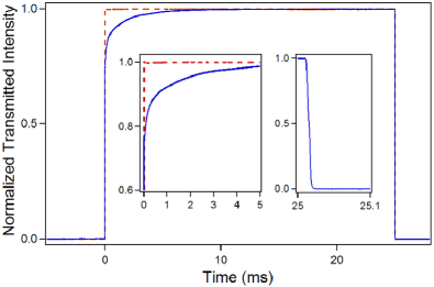
Figure 4 gives an example of detected signal obtained in such conditions. The power applied on the front face of the ruby crystal is modulated from 0 to 1.6 W by a 20-Hz square wave. The leading edge of the signal is characterized by an almost instantaneous jump which brings the signal to a value equal to 75% of its maximum value. This rapid variation is followed by a nearly exponential slow increase with a time-constant of about . In accordance with the incoherent bleaching model, on its trailing edge the signal quickly returns to zero with a 90%-10% switching time mainly introduced by the amplifier. Note that, for completeness, we have also performed experiments where the acousto-optic modulator was replaced by a mechanical chopper as in ko14 ; wi14 . The results obtained with both modulators are identical. Finally, although this parameter is not critical, we have measured the unsaturated optical thickness of the ruby crystal by collimating the beam inside the rod. The linear evolution of the transmitted power versus the input one leads to a mean value of close to 9.
To analyze the transmitted signals obtained in our experiments as those reported in ko14 ; wi14 , we come back to Eqs.(2, 3) which may be considered as the basis of the incoherent bleaching model. They first show that when . Analytical results valid at every time can be obtained when the medium thickness is such that , a condition met in the experiments. As in se67 ; ma08 , we introduce the function
| (21) |
| (22) |
and
| (23) |
In the case of a square incident pulse of the form where designates the Heaviside unit step function and is the pulse duration, we get
| (24) |
The transmitted pulse displays an initial discontinuity equal to at before rising as an exponential of exponential and falling to 0 at . If , it attains the asymptotic limit before falling. Note also that the rise is reduced to a simple exponential if . We have then
| (25) |
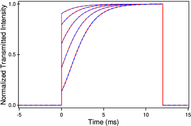
Figure 5 shows the results obtained for , , and, from top to bottom, and . Note that the analytical solution given by Eq. (24) perfectly fits the exact numerical solution as long as and that the shape of the transmitted pulse then does not depend on . The values and approximately correspond to the experiment of Fig. 4 and Eq. (25) satisfactorily holds in this case.
In order to determine the normalized population of the fluorescent metastable level (again in the limit ), we come back to Eq. (22) and replace by its approximate form given by Eqs.(24). After a tedious calculation, we get for the rise of the rather complex expression
| (26) |
with
| (27) |
where designates the exponential integral function ni10 . Equations. (26) and (27) hold for arbitrary . For , it immediately results from Eq. (3) that, without any restriction on and , is reduced to a decreasing exponential of time constant , namely
| (28) |
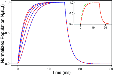
Figure 6 shows the evolution of the population of the fluorescent metastable level obtained for the intensities already considered in Fig.5. We see that Eqs. (26)-(28) perfectly fit the exact numerical solutions. When , Eq.(26) becomes at the lowest order in
| (29) |
Equations.(29) and (28) are identical to those describing respectively the charge and the discharge of a capacity through a resistance with . As shown in the inset of Fig. 6, they provide a satisfactory approximation of the exact result for as large as .
Our experimental results on the transmitted pulse obtained for an incident square pulse confirms those obtained by Kozlov et al. ko14 and are in good agreement with our calculations based on the incoherent bleaching model. The key points are (i) presents a discontinuity followed by an exponential-like rise when the incident beam is switched on (ii) immediately falls to 0 when the incident beam is switched off. Quite different results are reported by Wisniewski et al. wi14 : There is no initial discontinuity of and falls down exponentially with a time constant of about when the incident beam is switched off. In these experiments, the signal hardly exceeds the dark signal of the detector and the signal-to-noise ratio is poor compared to that obtained by Kozlov et al. and in our experiments. The shape of the observed signals strangely resembles that of the evolution of the fluorescent metastable level population obtained in the incoherent bleaching model (Fig. 6). It thus seems that the light actually observed in wi14 is nothing but fluorescence light. The fact that “the delays of the individual Fourier components [of the observed signal] are independent of the modulation frequency” as noted in wi14 simply reflects that, for moderate saturations, the population practically evolves as the voltage in an RC circuit [see inset of Fig. 6 and Eqs. (28 and (29)]. Wisniewski et al. add “the shape of the tail should be independent of the modulation frequency of the pulse”. Equation. (28) shows that it is actually the case for whatever the saturation is. Otherwise said, all the experimental results reported in wi14 are quite compatible with the incoherent bleaching model insofar as the observed light seems to be fluorescence light and not the light transmitted at the laser frequency.
IV Summary and discussion
Our article confirms the validity of the bleaching model to analyze the slow transmission of light pulses through saturable absorbers. Most experiments of so-called “Slow light based on (by means of, via) coherent population oscillations” are fully explained by the incoherent bleaching model. The very expression of coherent population oscillations is misleading. Indeed coherence in the optical sense generally plays no role in these experiments and the population oscillations at the low frequency of the intensity modulation are a trivial consequence of the equations coupling intensity and populations in saturable absorbers gi65 ; se67 ; se70 ; se71 ; pi07 ; ma08 . The population change being delayed with respect to the modulation (Fig. 1), the attribution of the origin of the slow transmission of the modulation to the population oscillations is questionable. We finally remark that the concept of group velocity as defined for pulses of coherent light does not apply to the broadband light considered in most experiments. It is, however, possible to define a group delay for the modulation [Eq. (18)] and even to establish a generalized Kramers-Kronig relation between its phase and its amplitude [Eq. (9)]. Note that these results are consistent with the CPO model as revised in pi07 and that the equations obtained in the latter are only local expressions of the integral equations derived in the incoherent bleaching model. An important point is that the modulation group delay has an upper limit equal to the medium response time no matter the medium thickness and is often much shorter. See Fig. 1 and 2. This situation contrasts with that encountered in “pure” slow light experiments performed with coherent light where the time delays do not suffer such limitations bo05 . As soundly remarked in se09 , it thus appears that the slow transmission in saturable absorbers reflects “slow response” of the medium rather than, strictly speaking, “slow light”.
The above analysis essentially concerns the transmission of light pulses superimposed on a large background. For saturating pulses without background, the range of validity of the CPO model, based on linearized equations, is artificially extended in bi03 ; wi14 by invoking a mechanism of self-pumping, one part of the pulse acting as a pump and the remaining part as a probe. Without any theoretical justification, this model gives pulse shapes that are qualitatively inconsistent with those derived in the incoherent bleaching model se67 ; se70 ; ma08 and actually observed for organic dyes kh67 ; he68 . The recent claim of the failure of the incoherent bleaching model to explain the pulse shapes observed in the reference case of ruby at room temperature wi13 originates two complementary experiments with this material ko14 ; wi14 . Incident square wave pulses were used in these experiments, the main point being that, in the bleaching model, the transmitted light should immediately vanish at the instant where the incident light is switched off. The experiments were performed with similar setups but, surprisingly enough, gave opposite results. The first one ko14 validates the bleaching model whereas the following one wi14 shows an exponential-like fall of the transmitted pulse when the incident light is switched off. No explanation was given in wi14 of this discrepancy. Our experiments and our theoretical calculations of the transmitted pulse shape and of the ruby fluorescent metastable state population bring some light on the problem. Our experimental result (Fig. 4) not only shows that the observed signal falls to 0 at the end of the square but that its rise is also in agreement with that predicted by the bleaching model (Fig. 5). The apparently opposite result obtained in wi14 can be explained by examining the theoretical evolution of the population of the fluorescent state (Fig. 6) that strangely resembles the observed signal in wi14 . We believe that the latter is caused by the fluorescence and the incoherent bleaching model is thus entirely validated.
We are grateful to Professor E. Zhukov at Dortmund Technical University who kindly provided us the ruby crystal rod used in our experiments. This work has been partially supported by Ministry of Higher Education and Research, Nord-Pas de Calais Regional Council and European Regional Development Fund (ERDF) through the Contrat de Projets État-Région (CPER) 2015–2020, as well as by the Agence Nationale de la Recherche through the LABEX CEMPI project (ANR-11-LABX-0007).
References
- (1) R.W. Boyd and D.J. Gauthier, “Slow” and “fast” light, Prog. Optics 43, 497 (2002).
- (2) R.W. Boyd, Slow and fast light: fundamentals and applications, J. Mod. Opt 56, 1908 (2009).
- (3) B. Macke and B. Ségard, Propagation of light-pulses at a negative group-velocity, Eur. Phys. J. D 23, 125 (2003).
- (4) B. Macke and B. Ségard, Pulse normalization in slow-light media, Phys. Rev. A 73, 043802 (2006).
- (5) H. Tanaka, H. Niwa, K. Hayami, S. Furue, K. Nakayama, T. Kohmoto, M. Kunitomo, and Y. Fukuda, Propagation of optical pulses in a resonantly absorbing medium: Observation of negative velocity in Rb vapour, Phys. Rev. A 68, 053801 (2003).
- (6) R.M. Camacho, M.V. Pack, and J.C. Howell, Low-distortion slow light using two absorption resonances, Phys. Rev. A 73, 063812 (2006).
- (7) R.M. Camacho, M.V. Pack, J.C. Howell, A. Schweinsberg, and R.W. Boyd, Wide-bandwidth, tunable, multiple-pulse-width optical delays using slow light in Cesium vapour, Phys. Rev. Lett. 98, 153601 (2007).
- (8) A. Kasapi, M. Jain, G. Y. Yin, and S. E. Harris, Electromagnetically induced transparency: Propagation dynamics, Phys. Rev. Lett. 74, 2447 (1995)
- (9) K.Y. Song, M.G. Herraez, and L. Thévenaz, Long optically controlled delays in optical fibers, Opt. Lett. 30, 1782 (2005).
- (10) L.V. Hau, S.E. Harris, Z. Dutton, and C.H. Behroozi, Light speed reduction to 17 metres per second in an ultracold atomic gas, Nature (London) 397, 594 (1999).
- (11) E.B. Alexandrov and V.S. Zapasskii, Chasing ‘slow light’, Phys. Usp. 49, 1067 (2006).
- (12) F. Gires and F. Combaud, Saturation de l’absorption optique de certaines solutions de phtalocyanines, J. Phys. (Paris) 26, 325 (1965).
- (13) A.C. Selden, Pulse transmission through a saturable absorber, Brit. J. Appl. Phys. 18, 743 (1967).
- (14) A.C. Selden, Analysis of the saturable absorber transmission equation, J. Phys. D 3, 1935 (1970).
- (15) V.E. Khartsiev, D.I. Stasel’ko, and V.M. Ovchinnikov, Reduction of pulse duration in a resonantly absorbing medium of high optical density, Sov. Phys. JETP 25, 965 (1967).
- (16) M. Hercher, W. Chu, and D.L. Stockman, An experimental study of saturable absorbers for ruby lasers, IEEE J. Quantum Electron. 4, 954 (1968).
- (17) A.C. Selden, Comment on ”An experimental study of saturable absorbers for ruby lasers”, IEEE J. Quantum Electron. 5, 523 (1969).
- (18) K.W Smith and L. Allen, Incoherent bleaching and self-induced transparency, Opt. Commun. 8, 166 (1973).
- (19) L. Allen and J.H. Eberly, Optical resonance and two-level atoms (Dover, New York 1987). See in particular Section 5.4 (Incoherent saturation and pulse delay).
- (20) A.C. Selden, Nonlinear transmission of an optical signal, Electron. Lett. 7, 287 (1971).
- (21) L.W. Hillman, R.W. Boyd, J. Krasinsky, and C.R. Stroud, Observation of a spectral hole due to population oscillations in a homogeneously broadened optical absorption line, Opt. Commun. 45, 416 (1983).
- (22) M.S. Bigelow, N.N. Lepeshkin, and R.W. Boyd, Observation of ultraslow light propagation in a ruby crystal at room temperature, Phys. Rev. Lett. 90, 113903 (2003).
- (23) N.S. Bigelow, N.N. Lepeshkin, and R.W. Boyd, Ultra-slow and superluminal light propagation in a solid at room temperature, J. Phys. Condens. Matter, 16, R1321 (2004).
- (24) E. Baldit, K. Bencheikh, P. Monnier, J.A. Levenson, and V. Rouget, Ultraslow light propagation in an inhomogeneously broadened rare earth ion-doped crystal, Phys. Rev. Lett. 95, 143601 (2005).
- (25) N.S. Bigelow, N.N. Lepeshkin, H. Shin, and R.W. Boyd, Propagation of smooth and discontinuous pulses through materials with very large or very small group velocities, J. Phys. Condens. Matter 18, 3117 (2006).
- (26) P.C. Ku, F. Sedwick, C.J. Chang-Hasnain, P. Palinginis, T. Li, H. Wang, S.W.Chang, and S.L. Chuang, Slow light in semiconductor quantum wells, Opt. Lett. 29, 2291 (2004).
- (27) M. van der Pol, J. Mørk, and J.M. Hvam, Controllable delay of ultrashort pulses in a quantum dot optical amplifier, Opt. Express 13, 8032 (2005)
- (28) J. Mørk, R. Kjær, M. van der Pol, and K. Yvind, Slow light in a semiconductor waveguide at gigahertz frequencies, Opt. Express 13, 8136 (2005).
- (29) H. Su and S.L. Chuang, Room temperature slow and fast light in quantum-dot semiconductor optical amplifier, Appl. Phys. Lett. 88, 061102 (2006).
- (30) P.C. Ku, C.J. Chang-Hasnain, and S.L. Chuang, Slow light in semiconductor heterostructures, J.Phys.D : Appl. Phys. 40, R93-R107 (2007).
- (31) A. Schweinsberg, N.N. Lepeshkin, M.S. Bigelow, R.W. Boyd, and S. Jarabo, Observation of superluminal and slow light propagation in erbium-doped optical fiber, Europhys. Lett. 73, 218 (2006).
- (32) F. Arieta-Yáñez, O.G. Calderón, and S. Melle, Slow and fast light based on coherent population oscillations in erbium-doped fibres, J. Opt. 12, 104002 (2010).
- (33) K. Bencheikh, E. Baldit, S. Briaudeau, P. Monnier, J.A. Levenson, and G. Mélin, Slow light propagation in a ring erbium doped fiber, Opt. Express 18, 25642 (2010).
- (34) S. Jarabo, Experimental evidence of coherent population oscillation based on spectral hole-burning in erbium-doped silica fibre, EPL 112, 14004 (2015).
- (35) V. Huet, A. Rasoloniaina, P. Guillemé, P. Rochard, P. Féron, M. Mortier, A. Levenson, K. Bencheikh, A. Yacomotti, and Y. Dumeige, Millisecond photon lifetime in a slow-light microcavity, Phys. Rev. Lett. 116, 133902 (2016).
- (36) V.S. Zapasskii and G.G. Kozlov, A saturable absorber, coherent populations oscillations, and slow light, Opt. Spectrosc. 100, 419 (2006)
- (37) B. Macke and B. Ségard, Slow light in saturable absorbers, Phys. Rev. A 78, 013817 (2008).
- (38) A.C. Selden, Slow light and saturable absorption, Opt. Spectrosc. 106, 881 (2009).
- (39) E. Wisniewski-Barker, G. Gibson, S. Franke-Arnold, Z. Shi, R.W Boyd, and M.J. Padgett, Evidence of slow-light effects from rotary drag of structured beams, New J. Phys. 15, 083020 (2013).
- (40) G.G. Kozlov, S.V. Poltavtsev, I.I. Ryzhov, and V.S. Zapasskii, Comment on ‘Evidence of slow light effects from rotary drag of structured beams’, New J. Phys. 16, 038001 (2014).
- (41) E. Wisniewski-Barker, G.M. Gibson, S. Franke-Arnold, Z. Shi, P. Narum, R.W. Boyd, and M.J. Padgett, Experimental investigation of the transient dynamics of slow light in ruby, New J. Phys. 16, 123054 (2014).
- (42) S.E. Schwarz and T.Y. Tan, Wave interactions in saturable absorber, Appl. Phys. Lett. 10, 4 (1967).
- (43) Throughout our paper, we use lower-case (upper-case) omega to designate optical frequencies (low modulation frequencies).
- (44) M. Sargent III, Spectroscopic techniques based on Lamb’s laser theory, Phys. Rep. 43, 223 (1978).
- (45) G. Piredda and R.W. Boyd, Slow light by means of coherent population oscillations: laser linewidth effects, J. Eur. Opt. Soc. Rapid Publ. 2, 07004 (2007).
- (46) A. Godone, F. Levi, and S. Micalizio, Slow light and superluminality in the coherent population trapping maser, Phys. Rev. A 66, 043804 (2002).
- (47) Note that the oscillation frequency involved in go02 ranges in the microwave domain while only audio-frequencies take place in the experiments on saturable absorbers.
- (48) We use the definitions, sign conventions and results of the linear system theory. See, for example, A. Papoulis, The Fourier integral and its applications (Mc Graw Hill, New York, 1987).
- (49) We incidentally remark that the experimental results of bi03 ; bi04 ; ba05 have not been reanalyzed accordingly.
- (50) J.C.I. Dooges and J.P. O’Kane, Deterministic Methods in Systems Hydrology (CRC Press, Boca Raton, 2003), p.52.
- (51) in NIST Handbook of Mathematical Functions, edited by F.W.J. Olver, D.W. Lozier, R.F Boisvert, and C.W. Clark (Cambridge University Press, Cambridge, 2010), p.150.
- (52) R.W. Boyd, D.J. Gauthier, A.L. Gaeta, and A.L. Willner, Maximum time delay achievable on propagation through a slow-light medium, Phys. Rev. A 71, 023801 (2005); Erratum, Phys.Rev. A 72, 059903(E) (2005).