Spin wave propagation and spin polarized electron transport in single crystal iron films
Abstract
The technique of propagating spin wave spectroscopy is applied to a 20 nm thick Fe/MgO (001) film. The magnetic parameters extracted from the position of the resonance peaks are very close to those tabulated for bulk iron. From the propagating waveforms, a group velocity of 4 km/s and an attenuation length of about 6 m are extracted for 1.6 m-wavelength spin-wave at 18 GHz. From the measured current-induced spin-wave Doppler shift, we also extract a surprisingly high degree of spin-polarization of the current of 83. This set of results makes single-crystalline iron a promising candidate for building devices utilizing high frequency spin-waves and spin-polarized currents.
I Introduction
Future developments in the field of magnonicsKruglyak, Demokritov, and Grundler (2010) require high-performance magnetic films, in which spin waves (SW) can propagate without suffering too much attenuation. The corresponding figure of merit is the attenuation length , defined as the distance over which the spin-wave amplitude decays by a factor , which depends on the magnetic parameters of the film (saturation magnetization, thickness, magneto-crystalline anisotropy) and on the magnetic precession losses.Gurevich and Melkov (1996); Stancil and Prabhakar (2009) More precisely, is inversely proportional to the effective magnetic damping parameter of the film . The research in the field of magnonics is therefore concentrating on materials with low damping. One material of choice is Yttrium Iron Garnet (YIG), a ferrimagnetic insulator which exhibits damping factor in the range of , but which requires sophisticated growth technique, Liquid Phase Epitaxy for the relatively thick films used since the early days of spin-wave physicsGurevich and Melkov (1996); Stancil and Prabhakar (2009) or Pulsed Laser Deposition for the thinner films grown more recently.d’Allivy Kelly et al. (2013) Other drawbacks of YIG are its low saturation magnetization (about 0.18 T), which translates into relatively small group velocity and weak signals in inductive measurements, and the difficulty to interface it efficiently with standard spintronic elements such as spin-valves.
For these reasons, ferromagnetic metal films are being considered as a possible alternative. Indeed, their higher magnetic damping ( = 0.002 to 0.01) is compensated by their higher saturation magnetization (1 to 2 T) and their easier deposition and integration into spintronic stacks. Among the ferromagnetic metals considered so far, Permalloy () has been used extensively: this very soft material, usually grown in polycrystalline form using standard magnetron sputtering, is magnetically very homogeneous and has moderate values of damping (0.008) and saturation magnetization (1 T). It was used successfully in the last years to build many different nanomagnonic devices.Vlaminck and Bailleul (2008); Chumak et al. (2009); Demidov et al. (2011) Two other classes of metal films were also explored by the magnonic community: (i) Heussler alloysSebastian et al. (2012); Zhu et al. (2011), which are expected to have much smaller damping due to their half metallic character, but which remain quite delicate to obtain with very low values of damping, and (ii) CoFeB alloys,Yu et al. (2012); Demidov et al. (2014) initially developed for tunnel magnetoresistance stacks, which exhibit a moderate damping of about 0.004 but whose magnetic properties depend quite strongly on the annealing conditions. We believe that many other ferromagnetic metals could be explored, so that a good compromise could be find for specific measurement/application conditions. A first step in this direction consists in exploring the potential of the three elemental transition metal ferromagnets. Nickel and cobalt do not seem to be adequate, because the former exhibits a relatively large damping of about 0.03 (Ref. Bhagat and Lubitz, 1974) and the latter has an hexagonal hcp structure quite difficult to handle. Iron on the other hand combines several advantages: a small damping in the bulk (about 0.002, see Refs. Heinrich and Frait, 1966; Bhagat and Lubitz, 1974; van Bockstal and Herlach, 1990; Cochran et al., 1991, with similar values reported for single crystalline thin filmsUrban, Woltersdorf, and Heinrich (2001); Scheck, Cheng, and Bailey (2006)), a large saturation magnetization of 2.15 T, a bcc cubic structure allowing epitaxy over MgOYuasa et al. (2004) and GaAsBrockmann et al. (1999), and the possibility to include it in high performance TMR stacks.Yuasa et al. (2004)
In this work, we explore in details spin-wave propagation in a pure iron film grown on MgO (001), taking advantage of the many possibilities offered by the technique of propagating spin-wave spectroscopy (PSWS). We start by describing the experiment (Sec. II). Then we discuss how the magnetic parameters of the film are deduced from the spin-wave resonance frequencies (Sec.III) and how the SW propagation characteristics are extracted from the measured waveforms (Sec. IV). Finally (Sec. V), we describe current-induced spin-wave Doppler shift measurements allowing one to determine the degree of spin-polarization of the current.
II Experiment
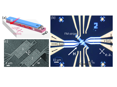
The Fe(001) film was grown by molecular beam epitaxy on a MgO(001) substrate. A 20 nm thick MgO buffer layer was first grown at 550∘C. Then, the t=20 nm Fe film was grown at 100∘C and annealed at 480∘C. Finally a MgO(8 nm)/Ti(4.5 nm) capping was deposited at room temperature. As usual for Fe/MgO(001) epitaxy, the [100] and [010] axis of Fe (which are easy axes for the cubic magneto-crystalline anisotropy) are rotated by 45∘ with respect to the [100] and [010] axis of MgO [Fig.1(a)].
.
Fig. 1(b) shows an optical microscope picture of an experimental device. It consists of a m wide strip oriented along Fe[100], patterned from the continuous film by photolithography and ion milling, and a pair of spin-wave antennas fabricated by electron beam lithography and lift-off of Ti(10 nm)/Al(120 nm). In addition, the device comprises a nm layer isolating the antennas from the strip and a set of Ti(10 nm)/Au(60 nm) contacts, including a pair of coplanar waveguides for microwave connections to the antennas and four pads for DC connections to the strip. A scanning electron microscope picture of the spin-wave antennas is shown in Fig. 1(c). The distribution of wave-vectors of the spin-waves generated by the antennas is governed by the Fourier transform of the spatial distribution of the microwave current, which contains a main peak at radm and a secondary peak at radm [see Fig. 8(b) in Ref. Vlaminck and Bailleul, 2010]. The external field H is applied in the film plane, perpendicular to the strip, i.e. parallel to the Fe[010] easy axis, so that the spin waves propagate in the so-called magnetostatic surface wave (MSSW) configuration.Stancil and Prabhakar (2009)
The measurements are carried out by PSWS, the operating principle of which is explained in detail in Ref. Vlaminck and Bailleul, 2010. Briefly, when a microwave current passes through one antenna it generates an oscillating magnetic field, therefore exciting spin waves which propagate in both directions along the strip. These spin wave induce an alternating voltage both on the excitation antenna and on the second antenna separated from the first by a distance . From the microwave reflection/transmission coefficients measured by a vector network analyzer connected to the two antennas , we extract the inductance matrix , which is analyzed as follows. The self-inductances exhibit absorption peaks associated with the excitation of spin waves. Following the position of these resonances as a function of the external field, one can derive the magnetic parameters of the film as with standard ferromagnetic resonance. The mutual-inductances exhibit oscillations. Following the amplitude and period of these oscillations as a function of allows one to extract the attenuation and the group velocity of the propagating spin waves.
III Determination of the magnetic parameters of the film
Fig. 2(a) shows the imaginary part of the self-inductance , which corresponds to the power absorption, measured at mT. One distinguishes two resonance peaks at 15 GHz and 18 GHz, which correspond to MSSWs with wave vectors and , respectively. An additional peak of very low intensity is observed at about 38 GHz, which is attributed to the first perpendicular standing spin wave mode (PSSW1), a higher order mode for which the precession in the upper half of the film is in anti-phase with respect to that in its lower half. The maximum intensity of the main peak is about 27 pH, which corresponds to changes in impedance and reflection coefficient of 3 and -30 dB, respectively. This is about 2.5 times larger than the intensity measured at the same frequency for a permalloy device with the same film thickness and lateral dimensions, thus confirming the advantage of using a material with a high saturation magnetization for such inductive measurements.
The variation of the frequency of the main MSSW peak as a function of the applied magnetic field is shown in Fig. 2(b) as diamonds. This variation is analyzed using the dispersion relation of MSSW:Stancil and Prabhakar (2009)
| (1) |
where is the gyromagnetic ratio, is the cubic anisotropy field, with the cubic anisotropy constant, is the effective magnetization which takes into account an additional perpendicular uniaxial anisotropy , and is the film thickness.111The standard expression of MSSW dispersion is modified to account for the cubic magnetic anisotropy of Fe and for a small perpendicular magnetic anisotropy of magneto-elastic and/or interface origin. The solid line in Fig. 2(b) was obtained by fitting the measured peak frequency to Eq. 1, which yields GHz/T, T, T and mT, corresponding to J/m3. To determine the value of the exchange constant , we use the PSSW1 peak, which in contrast to the MSSW peak is strongly influenced by the exchange interaction. Fitting the measured PSSW1 frequency [circles in Fig. 2(b)] to the Kalinikos-Slavin expressionKalinikos and N. (1986) with the values of the other magnetic parameters given above yields a value pJ/m.
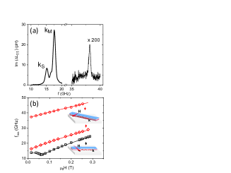
To illustrate directly the influence of the cubic anisotropy, we also use another device comprising a strip oriented along Fe[110] and measure it in the MSSW configuration (i.e. H is applied along Fe[], which is an in-plane hard axis). The field dependence of the frequency of the main MSSW peak for this device [squares in Fig. 2(b)] is quite different from that measured on the [100] strip. Indeed, when increasing the field, the peak frequency field first decreases up to a field of about 58 mT where it starts to increase, following the peak frequency of the [100] strip with a 116 mT shift towards higher field. The observed initial decrease of the peak frequency is attributed to the rotation of the magnetization vector M toward the field direction. In such a hard axis geometry, the precession frequency is expected to reach its minimum at the value of field needed to align M along H, and this value is equal to the anisotropy field . Determining numerically the angle of the equilibrium magnetization for each field, and calculating the corresponding MSSW frequency using the magnetic parameters indicated above [line in Fig. 1(b)], we obtain an excellent agreement with the experimental data, which confirms our determination of the cubic magnetic anisotropy. Note that all of the magnetic parameters determined in our film are in excellent agreement with those reported for bulk Fe.Craik (1995)
IV Spin wave propagation characteristics
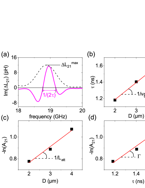
Following the procedure in Ref. Gladii et al., 2016a, we now analyze the mutual-inductance spectra in order to extract the characteristics of the propagating SW, namely their group velocity , attenuation length and magnetization relaxation rate . Figure 3(a) shows the imaginary part (solid line) and the magnitude (dashed line) of the mutual inductance measured at mT on a [100] strip with an edge-to-edge distance between antennas m. The measured waveform consists of an oscillation within an envelope having a peak shape. It can be characterized by two parameters: the period of the oscillation [the half of which is marked by a solid arrow in Fig. 3(a)] and its maximum amplitude .
The period can be identified with the inverse of the group delay time , where is an offset accounting for the finite-width of the antenna.Chang et al. (2014) Indeed, for two frequencies and close enough from each other, the difference of the propagation phase delays writes and amounts to for . To evaluate the group velocity, we extract the group delay times for three devices with different , perform a linear fit and identify the slope with [Fig. 3(b)]. To evaluate the attenuation length, the amplitude of the mutual-inductance is first normalized to those of the self-inductances. This yields the quantity , which is expected to decay exponentially with the distance as . We therefore plot as a function of , perform a linear fit and identify the slope with [Fig. 3(c)]. Finally, one can also evaluate directly the spin-wave relaxation rate , by plotting as a function of the measured , the slope of the linear fit being identified with [Fig. 3(d)]. This analysis yields the three SW propagation parameters related to each other through . For a frequency of 18.9 GHz they amount to km/s, m and rad/s.
In a next step, we follow the variation of the propagation characteristics as a function of the external field and compare them to theoretical predictions. Fig. 4(a) shows the measured and calculated values of the group velocity (squares and solid line, respectively). The latter is obtained by injecting the magnetic parameters given above in the expression derived from the MSSW relation dispersion [Eq. (1)], namely with and . The calculated are about 15 larger than the measured ones. We do not have an explanation for this difference yet, but we note that the overall agreement with the measurement is quite good. Fig. 4(b) shows the values of the effective damping , estimated from the measured using the relation appropriate for an in-plane magnetized thin film,Stancil and Prabhakar (2009) namely with . decreases significantly with increasing and reaches an asymptotic value of 0.0025 at high field. For comparison, the squares in the inset of Fig. 4(b) shows the frequency dependence of the resonance line-width measured on a similar Fe(20 nm)/MgO(001) film by broadband ferromagnetic resonance. Fitting the data to the expression ,Gurevich and Melkov (1996) we extract an inhomogeneous broadening mT and . The high field extrapolate of the SW effective damping is therefore in good agreement with the damping evaluated by FMR, which is also in line with the values measured in bulk FeHeinrich and Frait (1966); Bhagat and Lubitz (1974); van Bockstal and Herlach (1990); Cochran et al. (1991) and in epitaxial filmsUrban, Woltersdorf, and Heinrich (2001); Scheck, Cheng, and Bailey (2006). We attribute the increase of effective damping observed at low field to the additional spin-wave relaxation related to inhomogeneous broadening.
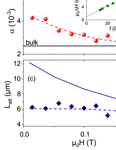
Finally, the diamonds in Fig. 4(c) show the measured , which has a nearly constant value of 6 m. Not surprisingly, this is significantly smaller than the ”ideal” attenuation length [dashed line in Fig. 4(c)] calculated using the theoretical expressions of and given above and a constant value of damping of 0.0025. From the analysis of panels (a) and (b), it is clear that this decrease arises both from a decrease of and a field dependent increase of . Despite this deviation, the attenuation length keeps a pretty large value in comparison with other materials. Indeed, for the same SW wavelength and film thickness and for a frequency of 19 GHz, the attenuation length is about 1 m in both permalloy () and YIG (). Note that, to reach such a SW frequency with these materials, the external field should be increased to 0.3 and 0.6 T, respectively.
V Current-induced spin-wave Doppler shift
In order to investigate the spin-polarized electrical transport properties of the iron film, we now resort to the technique of current-induced spin-wave Doppler shift (CISWDS), injecting a DC current in the strip and following the changes of the PSWS waveform.Vlaminck and Bailleul (2008) The effect occurs due to the interaction between the conduction electrons and the magnetization precession via the adiabatic spin transfer torque, which leads to a modification of the spin wave angular frequency taking the form of a Doppler shift . Here, is the SW wave-vector and is the effective spin drift velocity, which writes:
| (2) |
where is the degree of spin polarization of the electrical current, is the electrical current density, is the electron charge and is the Bohr magneton.
Fig. 5(a) shows the imaginary part of the mutual-inductance (dashed lines, which correspond to SW propagating from antenna 1 to antenna 2, i.e. ) and (solid lines, SW propagating from 2 to 1, i.e. ). The data are measured on the device with D=1 m and corresponds to the main MSSW peak. A field 120 mT is applied along Fe[010] and the electrical current flows along Fe[100]. One first notices that the waveform is more intense and shifted towards higher frequency as compared to the one. This is due to the well-known non-reciprocal effects in the MSSW configuration. The amplitude non-reciprocity is attributed to the circular polarization of the field produced by the antenna, which matches better the precession for one direction of propagation than for the other.Schneider et al. (2008) The frequency non-reciprocity is attributed to the combined effects of a non-reciprocal mode localization close to one film surface and an asymmetry of the magnetic anisotropy at the two film surfaces.Gladii et al. (2016b)
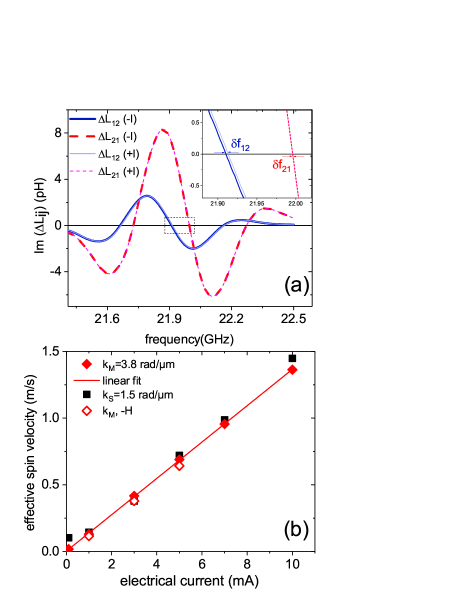
Let us now concentrate on the current-induced SW frequency shift. The inset of Fig. 5(a) shows a zoom allowing one to distinguish the frequency shift between the propagating waveforms recorded at I = +10 mA (thin solid line) and I =-10 mA (thick solid line). Note that the frequency shift between the two waveforms (thin and thick dashed lines) is not visible on this scale. Before analyzing these data one has to remove the influence of the Oersted field generated by the current by using the methods described in Refs. Haidar and Bailleul, 2013; Haidar et al., 2014. Due to some asymmetries across the film thickness (e.g. different probabilities of diffuse electron scattering on the two film surfaces), the Oersted field does not average strictly to zero. The resultant magnetic field adds to or subtracts from the external field and generates a current-induced SW frequency shift which is reciprocal (i.e. it does not depend on the SW propagation direction). To eliminate this effect, we consider the quantity .Haidar and Bailleul (2013) Another effect is the so-called non-reciprocal Oersted field-induced frequency shift, which results from the combination of the antisymmetric distribution of the Oersted field with the MSSW modal profile non-reciprocal asymmetry which develops across thick enough films. Using the theory of Ref. Haidar et al., 2014 and the parameters of our Fe film, we calculate a shift of the order of 50 kHz for a current of 10 mA, which is much smaller than the measured frequency shift [ kHz from the data in Fig.5(a)]. Solid diamonds in Fig. 5(b) show the effective spin-velocity , extracted as described above, and plotted as a function of the magnitude of the DC current . One recognizes a clear linear variation. From the slope of the linear fit, using Eq. 2 with the geometric and magnetic parameters of the Fe strip given above, we obtain a degree of spin-polarization of the electrical current . Note that very similar values of effective spin velocity are deduced from the current-induced frequency shift of the secondary MSSW peak [squares in Fig. 5(b)], and also for an external field of opposite sign [open diamonds in Fig. 5(b)], which is an indication that artifacts have been correctly accounted for by our extraction procedure.
The value we measure on our Fe film at room temperature (RT) can be compared to values determined using the same technique on different materials (P=0.5-0.7 for Vlaminck and Bailleul (2008); Zhu, Dennis, and McMichael (2010); Sekiguchi et al. (2012); Haidar and Bailleul (2013); Chauleau et al. (2014) and P=0.85-0.95 for Zhu et al. (2011)). In these two examples the large spin-polarizations are attributed to a strong spin-asymmetry of the electron scattering induced by the random alloy disorder, which could be understood from older works on impurity scattering in bulk ferromagnetic alloysCampbell and Fert (1982); Mertig (1999). In the case of a pure metal, such random alloy disorder scattering is absent and in our single-crystalline film, grain boundary scattering can also be ruled out. Diffuse electron scattering by the film surfaces is expected to have a small influence because the bulk electron mean free path, of the order of 2 nm,Gurney et al. (1993) is much smaller than the film thickness. Among the possible spin-dependent scattering processes listed in Ref. Haidar and Bailleul, 2013, we are left only with the contributions of thermal disorder, namely those of phonons (thermal disorder of the lattice) and magnons (thermal disorder of the local magnetization). This is confirmed by temperature dependent resistivity measurements carried out on a similar Fe(20 nm)/MgO(001) film, which yield a RT value of 11 .cm (similar to the one measured on the devices themselves, which is slightly larger than the 10 .cm value tabulated for bulk Fe) and a 5 K resistivity of only 1.5 .cm. Our result is a direct evidence of the strong spin-polarization of the electron scattering by thermal excitations in pure iron, which is a new finding. Indeed, deviations from the Matthiessen’s rule measured in bulk dilute alloys indicated a sizeable spin-polarization of the resistivity for nickelFert and Campbell (1976) and cobaltLoegel and Gautier (1971), but such extraction could not be done unambiguously for iron. Fert and Campbell assumed the pure iron contribution to the resistivity to be non-polarized, based on the fact that the electron density of states for the two spin channels are quite similar at the Fermi level.Fert and Campbell (1976)
On the contrary, we believe that in iron at room temperature, the phonon contribution to the electron resistivity is actually quite strongly spin-polarized, and that the magnon contribution, which has a tendency to depolarize the current because it is a spin-flip process, remains moderate. The latter statement is consistent with the findings of Raquet et al., who deduced a magnon contribution to the RT resistivity of the order of 2 .cm from high field magnetoresistance measurements.Raquet et al. (2002) Because the inclusion of thermal excitations in ab-initio electron transport calculations remains problematic, there are not many theoretical works we can compare with. Liu et al.Liu et al. (2015) and Ebert et al.Ebert et al. (2015) used frozen disorder approaches to obtain RT phonon contributions which amount to of 5 and 9 .cm, respectively. They could account for the 10 .cm tabulated value by matching the thermal spin disorder to the measured temperature dependence of the saturation magnetization. Following another method, for a high enough temperature , the phonon-contribution to the resistivity can be written , where is the unit cell volume, is the Boltzmann constant, is the density of states at the Fermi Energy, is the average over the Fermi surface of the square of the component of the electron velocity along the electrical field, and is the transport electron-phonon coupling parameter, obtained by a suitable averaging of the electron-phonon spectral distribution functions determined by ab-initio methods.Savrasov and Savrasov (1996) Using a realistic spin-polarized electron band-structure for Fe, Verstraete obtained and ,Verstraete (2013) an asymmetry associated with the fact that, at the Fermi level of Fe, minority and majority electrons correspond to different parts of the d-band. This asymmetry, when combined with those of the density of states and Fermi velocity, namely ,Zhu et al. (2008) results in a spin-polarization of the current of the order of 0.6, which is close to the value we measure. Interestingly, these two values are significantly higher than the value P=0.45 deduced from point-contact Andreev reflexion (PCAR) measurements on Fe films and foils.Soulen Jr. (1998) Indeed, the purely diffusive electrical transport regime probed in our room temperature CISWDS measurement is quite different from the partly ballistic regime probed in the low temperature PCAR technique. In the latter case, the spin-polarization is usually identified with that of ,Soulen Jr. (1998); Zhu et al. (2008) which depends only on the electron band structure. In our case, the spin-dependence of the electron-phonon coupling plays an additional role.
VI conclusion
In this work we have shown that single-crystal iron constitutes a material of choice for propagating spin-waves. The large saturation magnetization translates into a relatively high group velocity and inductive signals of large amplitude. Although it is field-dependent and slightly higher than in bulk Fe, the effective damping remains small (0.0025-0.004). Iron is particularly promising for high-frequency operation because of the sizeable cubic magneto-crystalline anisotropy, which shifts the zero-field spin-wave frequency well above 10 GHz. In the last part of this paper, we have also shown that diffusive electron transport in iron at room temperature is strongly spin-polarized, which is attributed to a significant spin-asymmetry of the electron-phonon coupling. This indicates that, despite the absence of spin-polarized impurity or surface scattering, a pure material such as iron can be used efficiently for generating spin currents. The present study can be seen as a starting point for the investigation of several Fe-based alloys in the context for magnonic applications. Indeed, some of these alloys are expected to exhibit much smaller dampingScheck et al. (2007); Devolder et al. (2013); Schoen et al. (2016) and larger spin-resistive signalsZahnd et al. (2015) than the Ni-based alloys extensively used up to now.
Acknowledgements.
The authors would like to thank F. Gautier, A. Fert, O. Bengone and H. Ebert for useful discussions, F. Abiza for the broadband FMR measurements, and the STnano facility and the Labex-NIE for giving us access to nanofabrication equipments. This work was supported by the Agence Nationale de la Recherche (France) under contract No. ANR-11-BS10-003 (NanoSWITI). O.G. thanks the Idex Unistra for doctoral funding.References
- Kruglyak, Demokritov, and Grundler (2010) V. V. Kruglyak, S. O. Demokritov, and D. Grundler, “Magnonics,” Journal of Physics D: Applied Physics 43, 264001 (2010).
- Gurevich and Melkov (1996) A. G. Gurevich and G. Melkov, Magnetization oscillations and waves, edited by A. G. Gurevich and G. Melkov (CRC Press, Boca Raton, 1996).
- Stancil and Prabhakar (2009) D. D. Stancil and A. Prabhakar, Spin Waves. Theory and applications, 1st ed., edited by D. D. Stancil and A. Prabhakar (Springer US, 2009).
- d’Allivy Kelly et al. (2013) O. d’Allivy Kelly, A. Anane, R. Bernard, J. B. Youssef, C. Hahn, A. H. Molpeceres, C. Carretero, E. Jacquet, C. Deranlot, P. Bortolotti, R. Lebourgeois, J.-C. Mage, G. de Loubens, O. Klein, V. Cros, and A. Fert, “Inverse spin hall effect in nanometer-thick yttrium iron garnet/pt system,” Appl. Phys. Lett. 103, 082408 (2013).
- Vlaminck and Bailleul (2008) V. Vlaminck and M. Bailleul, “Current-induced spin-wave doppler shift,” Science 322, 410–413 (2008).
- Chumak et al. (2009) A. V. Chumak, P. Pirro, A. A. Serga, M. P. Kostylev, R. L. Stamps, H. Schultheiss, K. Vogt, S. J. Hermsdoerfer, B. Laegel, P. A. Beck, and B. Hillebrands, “Spin-wave propagation in a microstructured magnonic crystal,” Appl. Phys. Lett. 95, 262508 (2009).
- Demidov et al. (2011) V. E. Demidov, M. P. Kostylev, K. Rott, J. Münchenberger, G. Reiss, and S. O. Demokritov, “Excitation of short-wavelength spin waves in magnonic waveguides,” Appl. Phys. Lett. 99, 082507 (2011).
- Sebastian et al. (2012) T. Sebastian, Y. Ohdaira, T. Kubota, P. Pirro, T. Brächer, K. Vogt, A. A. Serga, H. Naganuma, M. Oogane, Y. Ando, and B. Hillebrands, “Low-damping spin-wave propagation in a micro-structured co2mn0.6Fe0.4Si heusler waveguide,” Appl. Phys. Lett. 100, 112402 (2012).
- Zhu et al. (2011) M. Zhu, B. D. Soe, R. D. McMichael, M. J. Carey, S. Maat, and J. R. Childress, “Enhanced magnetization drift velocity and current polarization in (CoFe)[sub 1-x]ge[sub x] alloys,” Appl. Phys. Lett. 98, 072510 (2011).
- Yu et al. (2012) H. Yu, R. Huber, T. Schwarze, F. Brandl, T. Rapp, P. Berberich, G. Duerr, and D. Grundler, “High propagating velocity of spin waves and temperature dependent damping in a CoFeB thin film,” Appl. Phys. Lett. 100, 262412 (2012).
- Demidov et al. (2014) V. E. Demidov, S. Urazhdin, A. B. Rinkevich, G. Reiss, and S. O. Demokritov, “Spin hall controlled magnonic microwaveguides,” Applied Physics Letters 104, 152402 (2014).
- Bhagat and Lubitz (1974) S. M. Bhagat and P. Lubitz, “Temperature variation of ferromagnetic relaxation in the 3 d transition metals,” Phys. Rev. B 10, 179–185 (1974).
- Heinrich and Frait (1966) B. Heinrich and Z. Frait, “Temperature dependence of the FMR linewidth of iron single-crystal platelets,” physica status solidi (b) 16, K11–K14 (1966).
- van Bockstal and Herlach (1990) L. van Bockstal and F. Herlach, “Ferromagnetic relaxation in 3d metals at far infrared frequencies in high magnetic fields,” Journal of Physics: Condensed Matter 2, 7187–7193 (1990).
- Cochran et al. (1991) J. F. Cochran, J. M. Rudd, W. B. Muir, G. Trayling, and B. Heinrich, “Temperature dependence of the landau–lifshitz damping parameter for iron,” J. Appl. Phys. 70, 6545 (1991).
- Urban, Woltersdorf, and Heinrich (2001) R. Urban, G. Woltersdorf, and B. Heinrich, “Gilbert damping in single and multilayer ultrathin films: Role of interfaces in nonlocal spin dynamics,” Phys. Rev. Lett. 87 (2001), 10.1103/physrevlett.87.217204.
- Scheck, Cheng, and Bailey (2006) C. Scheck, L. Cheng, and W. E. Bailey, “Low damping in epitaxial sputtered iron films,” Applied Physics Letters 88, 252510 (2006).
- Yuasa et al. (2004) S. Yuasa, T. Nagahama, A. Fukushima, Y. Suzuki, and K. Ando, “Giant room-temperature magnetoresistance in single-crystal fe/MgO/fe magnetic tunnel junctions,” Nature Materials 3, 868–871 (2004).
- Brockmann et al. (1999) M. Brockmann, M. Zolfl, S. Miethaner, and G. Bayreuther, “In-plane volume and interface magnetic anisotropies in epitaxial fe films on GaAs(001),” Journal of Magnetism and Magnetic Materials 198-199, 384–386 (1999).
- Vlaminck and Bailleul (2010) V. Vlaminck and M. Bailleul, “Spin-wave transduction at the submicrometer scale: Experiment and modeling,” Physical Review B 81, 014425 (2010).
- Note (1) The standard expression of MSSW dispersion is modified to account for the cubic magnetic anisotropy of Fe and for a small perpendicular magnetic anisotropy of magneto-elastic and/or interface origin.
- Kalinikos and N. (1986) B. A. Kalinikos and S. A. N., “Theory of dipole-exchange spin wave spectrum for ferromagnetic films with mixed exchange boundary conditions,” Journal of Physics C: Solid State Physics 19, 7013 (1986).
- Craik (1995) D. Craik, Magnetism Principles and applications (John Wiley and sons, 1995).
- Gladii et al. (2016a) O. Gladii, M. Collet, K. Garcia-Hernandez, C. Cheng, S. Xavier, P. Bortolotti, V. Cros, Y. Henry, J.-V. Kim, A. Anane, and M. Bailleul, “Spin wave amplification using the spin hall effect in permalloy/platinum bilayers,” Appl. Phys. Lett. 108, 202407 (2016a).
- Chang et al. (2014) C. S. Chang, M. Kostylev, E. Ivanov, J. Ding, and A. O. Adeyeye, “The phase accumulation and antenna near field of microscopic propagating spin wave devices,” Appl. Phys. Lett. 104, 032408 (2014).
- Schneider et al. (2008) T. Schneider, A. A. Serga, T. Neumann, B. Hillebrands, and M. P. Kostylev, “Phase reciprocity of spin-wave excitation by a microstrip antenna,” Physical Review B 77, 214411 (2008).
- Gladii et al. (2016b) O. Gladii, M. Haidar, Y. Henry, M. Kostylev, and M. Bailleul, “Frequency nonreciprocity of surface spin wave in permalloy thin films,” Physical Review B 93, 054430 (2016b).
- Haidar and Bailleul (2013) M. Haidar and M. Bailleul, “Thickness dependence of degree of spin polarization of electrical current in permalloy thin films,” Phys. Rev. B 88 (2013), 10.1103/physrevb.88.054417.
- Haidar et al. (2014) M. Haidar, M. Bailleul, M. P. Kostylev, and Y. Lao, “Nonreciprocal Oersted field contribution to the current-induced frequency shift of magnetostatic surface waves,” Physical Review B 89, 094426 (2014).
- Zhu, Dennis, and McMichael (2010) M. Zhu, C. L. Dennis, and R. D. McMichael, “Temperature dependence of magnetization drift velocity and current polarization in ni 80 Fe 20 by spin-wave Doppler measurements,” Phys. Rev. B 81 (2010), 10.1103/physrevb.81.140407.
- Sekiguchi et al. (2012) K. Sekiguchi, K. Yamada, S.-M. Seo, K.-J. Lee, D. Chiba, K. Kobayashi, and T. Ono, “Time-domain measurement of current-induced spin wave dynamics,” Phys. Rev. Lett. 108 (2012), 10.1103/physrevlett.108.017203.
- Chauleau et al. (2014) J.-Y. Chauleau, H. G. Bauer, H. S. Körner, J. Stigloher, M. Härtinger, G. Woltersdorf, and C. H. Back, “Self-consistent determination of the key spin-transfer torque parameters from spin-wave Doppler experiments,” Phys. Rev. B 89 (2014), 10.1103/physrevb.89.020403.
- Campbell and Fert (1982) I. Campbell and A. Fert, “Ferromagnetic materials, vol. 3,” (North-Holland, 1982) Chap. Transport Properties of Ferromagnets, pp. 747–804, e.P. Wohlfarth, Ed.
- Mertig (1999) I. Mertig, “Transport properties of dilute alloys,” Rep. Prog. Phys. 62, 237–276 (1999).
- Gurney et al. (1993) B. A. Gurney, V. S. Speriosu, J.-P. Nozieres, H. Lefakis, D. R. Wilhoit, and O. U. Need, “Direct measurement of spin-dependent conduction-electron mean free paths in ferromagnetic metals,” Physical Review Letters 71, 4023–4026 (1993).
- Fert and Campbell (1976) A. Fert and I. A. Campbell, “Electrical resistivity of ferromagnetic nickel and iron based alloys,” Journal of Physics F: Metal Physics 6, 849–871 (1976).
- Loegel and Gautier (1971) B. Loegel and F. Gautier, “Origine de la resistivite dans le cobalt et ses alliages dilues,” Journal of Physics and Chemistry of Solids 32, 2723–2735 (1971).
- Raquet et al. (2002) B. Raquet, M. Viret, E. Sondergard, O. Cespedes, and R. Mamy, “Electron-magnon scattering and magnetic resistivity in 3 d ferromagnets,” Physical Review B 66, 024433 (2002).
- Liu et al. (2015) Y. Liu, Z. Yuan, R. J. H. Wesselink, A. A. Starikov, M. van Schilfgaarde, and P. J. Kelly, “Direct method for calculating temperature-dependent transport properties,” Phys. Rev. B 91 (2015), 10.1103/physrevb.91.220405.
- Ebert et al. (2015) H. Ebert, S. Mankovsky, K. Chadova, S. Polesya, J. Minár, and D. Ködderitzsch, “Calculating linear-response functions for finite temperatures on the basis of the alloy analogy model,” Phys. Rev. B 91 (2015), 10.1103/physrevb.91.165132.
- Savrasov and Savrasov (1996) S. Y. Savrasov and D. Y. Savrasov, “Electron-phonon interactions and related physical properties of metals from linear-response theory,” Physical Review B 54, 16487–16501 (1996).
- Verstraete (2013) M. J. Verstraete, “Ab initio calculation of spin-dependent electron–phonon coupling in iron and cobalt,” J. Phys.: Condens. Matter 25, 136001 (2013).
- Zhu et al. (2008) Z. Y. Zhu, H. W. Zhang, S. F. Xu, J. L. Chen, G. H. Wu, B. Zhang, and X. X. Zhang, “Intrinsic anisotropy of degree of transport spin polarization in typical ferromagnets,” J. Phys.: Condens. Matter 20, 275245 (2008).
- Soulen Jr. (1998) R. J. Soulen Jr., “Measuring the spin polarization of a metal with a superconducting point contact,” Science 282, 85–88 (1998).
- Scheck et al. (2007) C. Scheck, L. Cheng, I. Barsukov, Z. Frait, and W. E. Bailey, “Low relaxation rate in epitaxial vanadium-doped ultrathin iron films,” Phys. Rev. Lett. 98 (2007), 10.1103/physrevlett.98.117601.
- Devolder et al. (2013) T. Devolder, T. Tahmasebi, S. Eimer, T. Hauet, and S. Andrieu, “Compositional dependence of the magnetic properties of epitaxial FeV/MgO thin films,” Appl. Phys. Lett. 103, 242410 (2013).
- Schoen et al. (2016) M. A. W. Schoen, D. Thonig, M. L. Schneider, T. J. Silva, H. T. Nembach, O. Eriksson, O. Karis, and J. M. Shaw, “Ultra-low magnetic damping of a metallic ferromagnet,” Nat Phys (2016), 10.1038/nphys3770.
- Zahnd et al. (2015) G. Zahnd, L. Vila, T. V. Pham, A. Marty, P. Laczkowski, W. S. Torres, C. Beigné, C. Vergnaud, M. Jamet, and J.-P. Attané, “Comparison of the use of NiFe and CoFe as electrodes for metallic lateral spin valves,” Nanotechnology 27, 035201 (2015).