Reciprocity and optical chirality
Abstract
This text was published as Chapter 2 in Singular and Chiral Nano Plasmonics, Edited by S.V. Boriskina, N. I. Zheludev, PanStanford Publishing, pp. 57-96 (2015).
I Introduction
Chirality (or handedness as the word stems from the greek
meaning hand), refers to the lack or
absence of mirror symmetry of many
systems Landau ; Fedorov ; Hecht . It is a fascinating property having important consequences
in every areas of science. For example it is connected to several
fundamental problems such as the apparition of life, the origin of
homochirality (that is of single handedness) of many
biomolecules Masson , and also to the asymmetry between left
and right handed fermions with respect to electroweak
interaction Yang . Historically, I. Kant was one of the first
eminent scholar to point out the philosophical significance of
mirror operation. Already in 1783 in his celebrated “Prolegomena to
any future metaphysics” he wrote
“Hence the difference between
similar and equal things, which are yet not congruent (for
instance, two symmetric helices), cannot be made intelligible by
any concept, but only by the relation to the right and the left
hands which immediately refers to intuition.”Kant .
W. Thomson (Lord Kelvin), which was one of most important figure
of physics at the end of the XIX century defined
more precisely chirality in the following way:
“I call any geometrical figure or group of points, chiral
and say it has chirality, if its image in a plane mirror, ideally
realized cannot be brought to coincide with it
self.”Kelvin
The interest of Kelvin for chirality is not surprising. He played
himself a critical role in the foundation of electromagnetism and
thermodynamics, and he was well aware of the work presented in 1896
by M. Faraday on what is now known as the Faraday effect which is
intimately related to optical activity and chirality Faraday .
In this context, it is interesting to observe that like pasteur
after him Faraday also had fruitless attempts to establish some
relations between electricity, chirality and light, it was a letter
from Thomson in 1845 that actually led Faraday to repeat his
experiments with a magnetic field and to discover non
reciprocal gyrotropy (i.e. magnetic optical rotation)!
Remarquably, this
description of Kelvin provides an operational definition of chirality particularly suited to optics, as we illustrate below.
In optics indeed, since the pioneer work of Arago
Arago in 1811 and Biot in 1812 Biot , chirality is
associated with optical activity (natural gyrotropy), which is the
rotation of the plane of polarization of light upon going through a
3D chiral medium such as a quartz crystal or an aqueous solution of
sugar. The first mathematical description of optical activity arisen
from the work of Fresnel in 1825 Fresnel who interpreted
phenomenologically the effect in terms of circular birefringence,
that is as a difference in optical index for left and right handed
circularly polarized light (respectively written LCP and RCP)
passing through the medium. However, the intimate relationship
between optical activity and chirality became more evident after the
work of Pasteur Pasteur ; Flack in 1848 concerning the change
in sign of the optical rotatory power for enantiomorphic solution of
left and right handed chiral molecules of tartaric acid. In 1874, Le
Bel and van’t Hoff Lebel ; Hoff related rotatory power to the
unsymmetrical arrangements of substituents at a saturated atom, thus
identifying the very foundation for stereochemistry. Since then,
optical activity, including circular birefringence and dichroism,
the so-called Cotton effect Cotton , that is the difference in
absorbtion for LCP and RCP,
have become very powerful probes of structural chirality in a variety of media and environments.
With the recent advent of metamarials, that are artificially
structured photonic media, a resurgence of
interest concerning optical activity is observed. Current inspirations can be traced back to the pioneer work of Bose Bose who, as early as
1898, reported on the observation of rotatory power for
electromagnetic microwaves propagating through a chiral artificial
medium (actually left and right handed twisted jute elements). In
the context of metamaterials, Lindman in 1920 Lindman (see
also Tinoco and Freeman in 1957 Tinoco ) reported a similar
rotatory dispersion effect through a system of copper helices in the giga-Hertz (GHz)
range. Very recently, and largely due to progress in micro and nano
fabrication technics, researchers have been able to taylor
compact and organized optically active metamerials in the GHz
and visible ranges. It was for instance shown, that planar chiral
structures made of gammadions, i.e. equilateral crosses made of four bented arms, in
metal or dielectric, can generate optical
activity Pendry ; Papakostas ; Schwanecke ; Vallius ; Gonokami ; Canfield ; Canfield2 ; Zhang ; Decker ; Plum ; Rogacheva ; add1 ; add2 ; add3 ; Gansel ; Wegener ; Zhao
with giant gyrotropic factors Gonokami ; Decker ; Plum ; Rogacheva .
Important applications in opto-electronics and also for refractive
devices with negative optical index for
RCP and LCP, have been suggested in this context Pendry ; Wegener ; Zheludev .
These studies have raised an important debate on the genuine
meaning of planar chirality Papakostas ; Schwanecke ; Vallius . Indeed, since intuitively a
two-dimensional (2D) chiral structure, which is by definition a system which can not
be put into congruence with itself until left from the plane, is
not expected to display any chiral optical characteristics due to
the fact that simply turning the object around leads to the
opposite handedness. More precisely, it was
shown that since optical activity is a reciprocal property (that
is obeying to the principle of reciprocity of Lorentz, see below), it
necessarily implies that reversing the light path through the
medium must recreate back the initial polarization state. However,
since the sense of twist of a 2D chiral structure changes when looking from
the second side, this polarization reversal is impossible. It would otherwise
lead to the paradoxical conclusion that a left and right
handed structure generates the same optical activity in
contradiction with the definition, finally meaning that optical activity must
vanish in strictly planar chiral systems. This behavior strongly contrasts with
what is actually observed for 3D chiral objects having a helicoidal
structure (like a quartz crystal Arago ; Pasteur ; Flack , a
twisted jute element Bose , or a metal helix
Lindman ; Tinoco ), in full
agreement with the principle of reciprocity of Lorentz
Landau ; Lorentz ; Carminati ; Barron1 ; Barron2 since the sense of twist of
an helix is clearly conserved when we reverse back the
illumination direction. The experimental observation of
optical activity in gammadion arrays forces one to conclude that such systems must present a form of hidden 3D
chirality which turns fully responsible for the presence of
optical rotation that rules over the dominant 2D
geometrical chiral character
possessed by the system.
Things could have stop here, but the understanding of 3D chirality
was recently challenged in a pioneering study where it was shown
that chirality has a distinct signature from optical activity when
electromagnetic waves interact with a genuine 2D chiral structure
and that the handedness can be recognized Fedotov . While the
experimental demonstration was achieved in the GHz (mm) range for
extended 2D structures (the so called fish-scale
structuresFedotov ), the question remained whether this could
be achieved in the optical range since the optical properties of
materials are not simply scalable when downsizing to the nanometer
level. Theoretical suggestions were provided to overcome this
difficulty by using localized plasmon modes excited at the level of
the nanostructures Fedotov2 . Surface plasmons (SPs)
Barnes ; Genet ; Novotny are indeed hybrid photon/electron
excitations which are naturally confined in the vicinity of a metal
structure. As evanescent waves, SPs are very sensitive to local
variations of the metal and dielectric environments Barnes .
This property was thus used to tune some 2D chiral metal structure
to optical waves. Two series of experiences made in the near
infrared Fedotov3 with fishscale structure and in the visible
with Archimidian spirals Drezet1 ; Gorodetskisub confirmed the
peculiarity of genuine
2D chirality at the nanoscale.
In this chapter, we will review some fundamental optical properties associated, in full generality, with chiral systems. An algebraic approach will allow us to reveal in a simple way the underlying connexions between the concepts of chirality and reciprocity from which global classes of chiral elements will be drawned. These classes will be described with the framework of Jones matrices, enabling a clear discussion on their respective optical properties. Finally, a few examples taken from our recent work will be discussed as illustrative examples of the relevant of planar chirality in the context of nanophotonics.
II The reciprocity theorem and the principle of path reversal
II.1 The Lorentz reciprocity relation
In order to understand the physical meaning and implications of the different chiral matrices we will discuss we need to introduce the principle of reciprocity of Lorentz Lorentz ; Carminati ; Landau . First, we remind that, under the validity conditions of the paraxial approximation, the properties of light going through an optical medium are fully characterized by the knowledge of the Jones matrix
| (3) |
which ties the incident electric field
to the transmitted electric
field (defined in
the cartesian basis of the transverse plane). This corresponds
to the transformation
where is the operator associated with Eq. (3).
From the point of view of
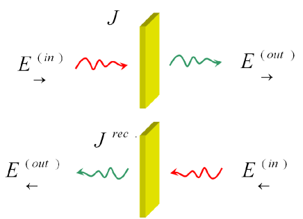
Jones matrices it is then possible to give a simple formulation of the reciprocity principle. Consider then a localized system illuminated by a plane wave propagating along the direction (see Fig.1). The arrow indicates the direction of propagation. The transmitted field (in the paraxial approximation) is given by . Same, we define also an incoming plane wave propagating along the direction impinging from the other side of the system and which after transmission gives the output state . Here by definition is the reciprocal Jones operator associated with . Using Maxwell equations one can easily show that where denotes the transposition in the cartesian basis . The proof reads as follow: first, from Maxwell equations one deduces Landau the reciprocity theorem of Lorentz which states that if in a passive and linear environment we consider two space points and then the vector field in produced by an (harmonic) point like dipole source located in is linked to the field in produced by a second point like dipole located in through the formula
| (4) |
(the time harmonic dependency has been dropped
everywhere).
Now, the electric field produced in by a point like
dipole located in is written
where denotes the dyadic Green
function for this environment Novotny . Equation (4) reads
thus
or equivalently in tensorial notation (). This relation is valid for every point dipoles in and and implies consequently
| (6) |
Actually, this relation constitutes a Maxwellian formulation of the principle of light path reversal used in optical geometry. In the next step of the proof we consider and located in the fields can be then considered asymptotically as plane waves and in the paraxial approximation identifies with the Jones matrix . We immediately see that the matrix identifies with the reciprocal matrix . In other words, from the point of view of Jones formalism, the principle of reciprocity states
| (9) |
In this context it is relevant to point out the similarity between the reasoning given here for establishing the reciprocity theorem and the one used in textbooks and articles Landau ; Fedorov ; Carminati for establishing the symmetry of the permittivity tensor () in solids. In particular, by taking into account spatial non-locality it is possible to obtain a version of the reciprocity theorem which reads:
where is the wavevector of the monochromatic plane wave. The analogy with Eq. (9) is complete if we choose the wave vector along the axis and if correspond to either or . Because of these similarities many reasoning done for the Jones matrix through this chapter could be easily restated for the electric permittivity or magnetic permeability tensors.
II.2 Rotation of the optical medium and reciprocity: conserving the handedness of the reference frame
Using the previous formalism the reciprocity principle give us a univocal way to calculate the transmitted light beam propagating in the direction through a structure if we know the transmission Jones matrix for propagation in the direction. However, we must remark that this formulation is not always the most convenient since we compare the Jones matrix from a situation in which the triplet of unit vectors built by , and the wavevector of the light wave (along z in the paraxial regime) constitute a right handed trihedra to a situation in which the same trihedra of vectors is left handed (since the sign of is opposite in the two situation). This in particular means that for an observer watching from one side of the medium a light beam coming from the other side the definition for LCP and RCP light as is different from the one obtained by an reciprocal observer watching from the side a light incident from the side, i.e., . In order to remove this ambiguity the principle of reciprocity can be reformulated by considering a reference frame transformation which is a global flip of the optical medium. More precisely, comparing directly to necessitates a rotation of the plane by an angle around . Mathematically this three dimensional transformation reads
| (13) |
The handedness of the 3-axis coordinate system is kept unchanged after the application of the reference frame transformation . It also implies that the full structure of Maxwell equation is also conserved, i.e., the optical effect is rigorously equivalent to a -rotation of the system around . In particular the wavevector
| (17) |
of the light going through the system transforms through into
| (21) |
From the point of view of the
Jones matrix simply reduces to that is to a planar mirror symmetry with
reflection axis parallel to . Through , the field vectors transform as , so that the Jones matrix
becomes .
Fundamentally it is interesting to note that a symmetry
operation, which is defined geometrically (and independently from
any set of physical laws), manifests itself specifically according
to a particular physical environment or context. From the point of
view of Maxwell’s equations this symmetry operation is indeed
implemented at the level of the susceptibility of the medium
interaction with light that is at the level of the Jones matrices.
Actually, the reciprocal transformation defined above constitutes a
rigorous and operational optical definition of the medium flipping
| (22) |
It will be also convenient in the following to express the electric field in the left (L) and right (R) circularly polarized light basis defined by . We write the Jones matrix in such basis, and we have
| (25) |
where defines the unitary matrix associated with this vector basis
transformation.
With these definition Eq. (22) reads in the RCP and
LCP basis
| (28) |
(remark that
since the transposition and the transformation are
not commutative operations).
To summarize, we showed that and
define the genuine representation
of reciprocity and path reversal in a coordinate system having the
same handedness as the original one (i.e. as seen from the other
side of the object). This corresponds to the axes transformation
, , and and it implies an exchange in the role
of LCP and RCP.
II.3 Time-reversal versus reciprocity
We point out that the reciprocity relations (22) and (28) should not be
confused with the time-reversal transform. Time-reversal is a
fundamental symmetry which dictates the invariance of physical laws
between exchange of past and future. In classical mechanics, this symmetry corresponds to a system described by its position and momentum which equations of motion are invariant through the transformation . While an isolated mechanical system is time-reversal, a real system is obviously always coupled with its environment, resulting in friction which immediately breaks the time-reversal symmetry.
In the presence of electromagnetic fields ,
, this time-reversal invariance is
preserved if in addition to the variables one also
transforms the field into
,
. In order
that Maxwell’s equation be automatically satisfied by the new
solutions the electric current and charge
distributions are changed accordingly into
,
. In the monochromatic
regime where fields, electric currents and charges are conveniently
described by their time-Fourier transforms at the positive pulsation
the time-reversal operation reads:
| (31) |
The time dependence is restored after integration over the pulsation
spectrum e.g.,
etc…
For optical situations where a modal expansion into
plane-waves of vector
,
is
considered ( being the complex-valued dielectric
permittivity of the medium) time-reversal implies new modal
components such as
| (33) |
where by definition
etc… In particular, if the medium is lossless, i.e.,
, the time-reversal operation
dictates in the propagative sector (i.e. for ) a change in the sign of the wave vectors
corresponding to a reversal of propagation direction for every
plane-waves of the modal expansion. Going back to the Jones matrix
formalism we can transform the relation
into
.
Now, from the previous discussion concerning time reversibility, the
complex conjugated input field
at
corresponds to the time-reversed output
computed at
whereas the complex conjugated output field
at
corresponds to the time reversed output
computed at .
The Jones matrix associated with time-reversal is therefore
| (36) |
As it is clear from its definition, is in general different from , exemplifying the importance of losses and dissipation in the relation between time reversibility and reciprocity in optics. The two operators are indeed identical if, and only if, is unitary, i.e., , meaning that an optical system through which energy is conserved and which is simultaneously reciprocal will be the only optical system to be time-reversal invariant. This reveals the non-equivalence between time reversibility and reciprocity. The latter is more general: reciprocity can hold for systems in which irreversible processes take place, as a fundamental consequence of Onsager’s principle of microscopic reversibility Casimir . In the context of planar chirality, this subtle link plays a fundamental role, as it will be discussed in section section.
III Optical chirality
III.1 Chiral Jones Matrix
Following the operational definition of Lord Kelvin, the study of chirality demands to characterize the optical behavior of the considered system through a planar mirror symmetry . By definition, an in-plane symmetry axis making an angle with respect to the -direction is associated with transformation matrices
| (41) |
respectively written in cartesian and circular bases with . Through that symmetry operation, the Jones matrix transforms as in the cartesian basis and as
| (44) |
in the circular basis.
With Kelvin’s definition, a system will be optically non-chiral if, and only if, it is invariant under , meaning that or equivalently that the operators respectively associated with the Jones matrix and the mirror-symmetry matrix commute as .
The invariance condition enforces two constraints on the Jones matrix coefficients, namely that
| (45) |
This implies that the Jones matrix associated with a non-chiral optical system has the following general form
| (48) |
By contrapositive of conditions (45), we see that
| Theorem: | ||||
| Optical chirality is possible if, and only if, | ||||
OR being the logical disjunction.
This constitutes a theorem equivalent to Kelvin’s statement that an optically chiral system has no mirror symmetry, with or, equivalently, with non-commuting operators respectively associated with the Jones matrix and the mirror-symmetry matrix as
| (49) |
Such a Jones matrix can be written in the following form:
| (54) | |||
| (55) |
Additionally for an optically chiral system, the application of a mirror symmetry provides new chiral optical structures called enantiomers which are characterized by their Jones matrices . By definition we have
| (56) |
In general, the lack of rotational invariance of
implies that these enantiomorphic matrices depend specifically on
the mirror reflection chosen in the
definition given by Eq. (55). Thus, there are actually infinite
numbers of such enantiomers.
Three important classes of chiral systems can be derived from the truth table associated with the theorem:
i) A first class satisfying but with
. For reasons presented below, this class will be named the “optical activity class” or
. This class is, until recently, the class essentially discussed in the literature.
ii) A second class corresponding to but satisfying the
constraint . This class will be named in the
following the “(genuine) planar chirality class” , for
reasons also to be given further down.
iii) A third class associated with and . This is the most general class of optically chiral system coined as the “optical chirality class” and which will be described below in details.
Our point is that these chiral classes correspond to specific spatial relations of chiral systems with respect to 3D space. Such relations are fundamental to the characterization of chiral objects, which depends on the shape of the objects and the dimension of the space within which the objects are probed Arnaut . In optics, these relations can be unveiled through reciprocity: as light propagates in 3D space, the effect of optical path reversal through any chiral object will reveal its relation with surrounding space. Analyzing the behavior of the objects concerning reciprocity allow characterizing the relation of any chiral objects with respect to 3D space, from which a classification of the chirality type can be drawn.
III.2 Optical activity
One of the most illustrating example of geometrical
chirality in nature is the helix. The helix is intimately linked
to the most know form of optical chirality namely optical activity
or natural gyrotropy. For example, several natural systems like
sugar molecules and quartz crystal possess a helicoidal structure
and show indeed optical activity properties such as rotatory power
i.e. circular birefringence, or circular dichroism (i.e. a
differential absorbtion for RCP and LCP light).
For the present
purpose one of the most relevant property of helices concerns their
sense of “twist”. It is indeed a basic fact that the twist orientation
of an helix with its axis along Z is invariant through the
rotation : such an helix looks actually quite the same
when watched by an observer in the or direction. This is mathematically rooted in the fact that the helix is a 3D object observed in a 3D space.
A particular application of the geometrical analogy is the case of
an isotropic and homogenous distribution of helices which is
indeed an extreme limit in which the system cannot be physically
(in particular) distinguished when watched from the front or the
back side. This is the case of the sugar molecules solution
considered by Arago and Pasteur in their pioneer works on optical
activity Arago ; Pasteur . However, it would be an
oversimplification to limit optical activity to such totally
invariant system since in general even an helix with its axis
oriented along is not completely invariant through
(although the sense of twist obviously is). Indeed, due to its
finite length one will have after application of in
general to rotate the helix by a given supplementary angle
around in order to return to the original helix
(as seen from the front side). The analogy with the
helix will give us a simple way to generalize our discussion and to define a criteria for optical activity.
More precisely, in the limit of the paraxial approximation
considered here the question we should ask to ourself is what must
be the precise structure of the Jones matrix if we impose that
(see Eq. (22)) is, up to a rotation
by an angle around the axis,
identical
to ?
This last condition reads actually in the cartesian basis
| (57) |
It is preferable to use the basis and the previous condition becomes
| (58) |
The rotation matrix is defined by
| (63) |
From equations (22,44,57), we deduce directly that the previous condition imposes (i.e., ). Therefore the Jones matrix takes the following form
| (66) |
By comparing with the condition for the absence of mirror symmetry (see Eq. (49)) and our theorem we see that this matrix is chiral if and only if . The class of all the matrices
| (69) |
fulfilling these conditions is physically associated with the phenomenon of optical activity. This justifies the name given to . Equivalently stated this result means that Eq. (69) defines the most general Jones matrices which are i) chiral and ii) such that the optical signature of chirality is, up to a rotation , invariant after reversal of the direction of propagation through the system. Clearly, reciprocity here dictates the rules. Importantly, Eq. (69) can also be written
| (74) |
that is as the sum of a matrix obeying Eqs. (45,48) (i.e., having an in-plane mirror symmetry axis) and of a matrix (with ) which actually induces the chiral behavior. In the cartesian basis we can equivalently write
| (80) |
with , and . The presence of the antisymmetrical part is the
signature of chirality and the coefficient is called
(natural) gyromagnetic factor.
An important particular case concern Jones matrices which
are invariant through a rotation by an angle around the
axis. Such a rotation is defined by the matrix
with
| (85) |
The invariance by rotation implies that the matrix equals , that is:
| (88) |
If then Eq. (88) is clearly a
particular case of Eq. (69) which actually describes optical
activity in isotropic media, such as quartz crystals or molecular
solutions, and corresponds to the circular birefringence (and
dichroism) introduced by Fresnel in 1825. It is interesting to
observe that this is also the matrix which is associated with the
gammadions artificial structure considered in
Papakostas ; Schwanecke ; Vallius ; Gonokami and which have a
four-fold rotational invariance around .
Following its definition, the Jones enantiomorphic matrix
associated with
writes as . Because of rotational invariance,
is
independent of . These two enantiomorphic matrices are
associated with opposite optical rotatory powers.
Consider for example the Jones matrix associated with
optical activity in an isotropic medium, such as a random
distribution of helices for example. From
Eqs. (22,56,88) it is immediately
seen that . This
invariance means that an observer illuminating such a system cannot
distinguish the two sides from one other. This well known property
explains in particular why an optically active medium cannot be used
as an optical isolator: reciprocity prohibits such a scenario. In
this context we point out that nothing here forbid unitarity to
hold. In the particular case of a Jones matrix represented by a
rotation (see Eq. (63)) we have indeed . We will
see in the next section that this is not the case for 2D chirality
where losses are unavoidable.
It is finally useful to remark that the ensemble of all the
matrices , i.e.,
, is not closed for the addition and the
product of matrices (that is the sum or the product of chiral matrix
belonging to is not necessary contained in
). For example by combining two enantiomers
characterized by the matrices and we get
| (95) | |||
| (102) |
which are obviously not chiral and correspond to
what is called a racemic medium (that is a mixture or a
juxtaposition of opposite enantiomers).
We point out that the
rotation matrices considered in the present discussion involve only
an axis of rotation oriented along the direction. It could be
interesting to consider more general 3D rotation with an axis
arbitrarily oriented. However, the case of planar chirality to be
considered in the next section would thus be problematic in our
classification since as stated in the introduction a planar chiral
structure can be brought into congruence with its mirror image if it
is lifted from the plane. The classification used here which
consider explicitly as distinct the two ensembles
and will appear actually
very convenient since (as shown in section 3.4) any chiral matrix
can be split into a first matrix belonging to
and a second matrix belonging to .
III.3 Planar chirality
Despite its fundamental importance the previous analysis of
optical activity does not exhaust the problem of chirality in optics. As we wrote in the introduction, 2D chirality characterizes, by definition, a system which
can not be put into congruence with itself until left from the
plane (for a more mathematical discussion see
Arnaut ; Osipov ). This corresponds to a different chirality class than optical activity, as it can be simply seen. If instead of a 3D helix one considers a 2D spiral contained within the
plane, one has obviously a system that has a dimension lower than the dimension of its surrounding space. A flip of the structure is now possible, when it was not for the helix. As we discussed above, this discussion corresponds optically to a change of twist orientation when the light path is reversed, and clearly motivates the experimental demonstration for this second
class of chiral objects which are planar.
Two geometrical examples of such planar
chiral object are the Archimedean spiral which has not point
symmetry and the gammadion which possesses rotational invariance.
Since optically gammadion are associated with gyrotropy i.e.
essentially 3D effect as discussed in the previous section we can
already think that such gammadions are not genuine 2D chiral object
from the optical point of view (even though it is obviously the case
from basic geometrical considerations). We will here consider more
in details this 2D chirality class of
Jones matrices, i.e, .
The planar chirality class
was until very recently completely ignored in
the literature and concerns chiral systems characterized by the
conditions and a Jones matrix of the form:
| (105) |
The condition
actually leads to chirality. As we will show below, the equality condition on diagonal elements correspond to reciprocity.
It is also important to observe that, since Eq. (105) is
different from Eqs. (45,88), the matrix
not only has no mirror symmetries,
but it has additionally no rotational invariance. This means, that
can only be associated with chiral
systems without any point symmetries, such as for example an
Archimedean spiral or a fish-scale structure. A gammadion structure
with its four-fold rotational invariance can not display such
optical property. It should also be remarked that the fish-scale
structure considered in Ref. Fedotov actually has a central
point symmetry, i.e., a two-fold rotation axis. However from the
point of view of Jones matrix such transformation is equivalent to
the identity, as it is immediately seen by writing
in Eq. (85), and consequently the structure of is not
constrained by such transformation.
Same as for one can define
enantiomers structures by the relation
| (108) |
of course belongs to .
We will now go back to the reciprocity theorem and consider
the properties of planar chiral system from the point of view of
path reversal. Same as for optical activity the geometrical analogy
appears very convenient for characterizing the reciprocal
properties of chiral planar systems. The archetype of planar chiral
objects is, as we already mentioned, the Archimedean spiral with
no point symmetry. Watching such a spiral from one side or the
other changes obviously the sense of twist. This contrasts strongly
with the case of the helix of of gammadion discussed before. This
suggests the following definition: the chiral system characterized
by the the Jones matrix is plan chiral if and only if Eq. (49) is
satisfied and if
| (109) |
where
corresponds to a particular enantiomorphic Jones matrix of (see
Eq. (108)) parameterized by the angle .
This condition is in the basis equivalent to
| (114) |
which admits a solution if and only if and or . Since (i.e., the identity operator) it means that the rotation plays here no role in the definition and that we could have reduced our reasoning to the condition
| (115) |
Additionally, in order to satisfy Eq. (49) we must necessarily have
. This is rigorously equivalent to the
definition of the class given above.
In the cartesian basis this means
| (118) |
with , and
. The condition for chirality
implies and
. This condition for chirality also implies a stronger
restriction:
Indeed, writing the non-diagonal coefficients , in
the polar form and (with
, the norms and , the phases) we can define the
ratio
which thus becomes
| (119) |
The condition for chirality therefore implies:
| (120) |
In the context of planar chirality it is also useful to check if is closed with respect to the matrices addition and multiplication. Same as for , it is obvious that this is not the case since by summing
| (123) |
and
| (126) |
one get
| (129) |
which does not belong to
(indeed, we have ).
Similarly, for the product of and
one obtain
which for the same reasons does not also belong to
.
Finally, we point out that all genuine 2D chiral systems share
an other important property namely a breaking of time invariance
or reversal Fedotov ; Fedotov2 ; Fedotov3 ; Drezet1 . To
understand this peculiarity we go back to our discussion of time
reversal and consider the condition that the Jones matrix
defined by Eq. (105) should fulfill in order to
be unitary, i.e.,
. From Eq. (123)
this leads to the relation:
| (134) |
This implies
,
and
. By taking the
norms of each terms we deduce and
. This last equality contradicts the definition
of and consequently such a planar chiral Jones
matrix can not be unitary. This implies that and that therefore is
different from .
In other words, a 2D chiral
system provides a perfect illustration that time-reversal is necessary different from reciprocity, i.e.
path reversal. Since time-reversal is a key property of
fundamental physical laws at the microscopic level, the only
solution is to assume that this breaking of time-reversal at the level of 2D chiral objects is
associated with macroscopic irreversibility. Indeed, the imaginary
part of the permittivity, for example, is connected to losses and
dissipation into the environment (seen as a thermal bath) and the condition for its
positivity implies a strong irreversibility in the propagation.
Similarly here, 2D optical chirality means that some sources of
irreversibility must be present in order to prohibit unitarity of
the Jones matrix. This is an interesting example where two
fundamental aspects of nature namely chirality and time
irreversibility (intrinsically linked to the entropic time arrow)
are intimately connected.
III.4 Generalization
The most general Jones matrix characterizing a chiral medium can be written:
| (139) |
where both conditions , are
satisfied. This defines the optical chirality class
.
An important property is that the sum of
a matrix belonging to with a matrix of
belongs to . To see that
this is obviously the case it is sufficient to remark that the sum
of a matrix with a matrix
can be written
| (143) |
However we also have
| (146) |
with . This is necessary of the form since otherwise we should have in contradiction with the condition . Reciprocally any matrices can be written as a sum since from the previous result for any the difference belongs to . This means that a matrix belonging to can always be written as the sum of a matrix belonging to the class with a matrix belonging to . Interestingly, the combination of a spiral and an helix leads to the geometrical shape of the screw. Finally, one can observe that is not close with respect to the matrix addition and product since it is already not the case for the sub classes and .
III.5 Eigenstates and chirality: time reversal versus reciprocity
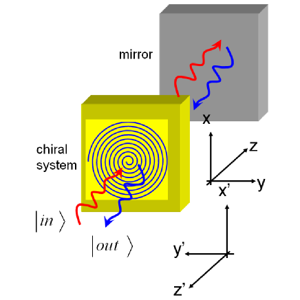
In the context of reciprocity it is of practical importance to consider the backward propagation of light through the medium along the z direction after path reversal by a mirror located after it (see Fig. 2). This corresponds to the following succession of events: 1) the initial state, that we write here (instead of used in section II.1), propagates through the chiral medium and we obtain afterward the new state . 2) The reflection by the mirror induces a change in the electric field sign and also reverses the path propagation direction. By rotating the coordinate axes by an angle around the axis we preserve (as explained before) the handedness of such coordinate system as well as the positive sign of the propagation direction. This means, that in this new basis the vector evolves as . 3) The backward propagation through the medium is described by the ’flip’ operator and the final state (in the new coordinate system) reads . We have consequently
| (148) |
where by definition
.
In order to analyze the effect of Eq. (148) we will
first study more in details the eigenstates and eingenvalues of the
chiral Jones matrix discussed in this chapter. First, we consider the case of optical activity where
| (151) |
The two eigenstates are and corresponding to eigenvalues and respectively. However, and while the two eigenstates of are still and the eigenvalues are now exchanged i.e. and respectively. Therefore, a direct application of Eq. (148) on any vector lead to
| (152) |
If we are only interested into the field expression in the original coordinate system we can alternatively rewrite
| (153) |
This is a direct formulation of the fact that path
reversal should lead us here back to the initial state
as expected. It illustrates the impact of reciprocity on
propagation and show that a 3D chiral medium doesn’t act as an
optical isolator. We also point out that for a loss-less ideal
medium represented by a unitary rotation matrix
with
eigenvalues we have exactly
which, up to the minus sign
coming from the mirror reflection, is a perfect illustration of time
reversal and symmetry for natural optical activity.
We now consider 2D planar chirality. The eigenstates and
eingenvalues of the chiral Jones matrix
| (156) |
are by definition states defined by . After straightforward calculations we obtain
| (157) |
and
| (158) |
Using similar methods we can easily find eigenstates and values of the reciprocal matrix such as . The eigenvalues are the same as for ,i.e., but the eigenvectors are now
| (159) |
Importantly here and therefore by applying Eq. (148) on the initial states we get
| (160) |
where we used the relations , , and . Like we did for optical activity we can go back to the initial coordinate system and the final states read now
| (161) |
As before that again illustrates the effectiveness of the reciprocity principle. Furthermore, since the transformation is not unitary we could not obtain such a result using as defined by Eq. (36).
IV Discussion and examples
As we mentioned in the introduction it is very interesting
to observe that the property concerning the change of twist for
genuine 2D chiral systems when watched from two different sides
stirred a considerable debates in the recent year in the context
of metamaterials. To understand this more in details we
remind that partly boosted by practical motivations, such as the
quest of negative refractive lenses Pendry or the
possibility to obtain giant optical activity for applications in
optoelectronics, there is currently a renewed
interest Pendry ; Papakostas ; Schwanecke ; Vallius ; Gonokami ; Canfield ; Canfield2 ; Zhang ; Decker ; Plum ; Rogacheva
in the optical activity in artificial photonic media with planar
chiral structures. It was shown for instance that planar
gammadionic structures, which have by definition no axis of
reflection but a four-fold rotational
invariance Papakostas ; Vallius , can generate optical
activity with giant gyrotropic
factors Gonokami ; Rogacheva ; Plum ; Decker . Importantly, and in
contrast to the usual three dimensional (3D) chiral medium (like
quartz and its helicoidal structure Hecht ; Bose ), planar
chiral structures change their observed handedness when the
direction of light is reversed through the
system Papakostas ; Barron1 . This paradoxically challenged
Lorentz principle of reciprocity Landau (which is known to
hold for any linear non magneto-optical media) and stirred up
considerable debate Papakostas ; Schwanecke ; Gonokami ; Barron2
which came to the conclusion that optical activity cannot be a
purely 2D effect and always requires a small dissymmetry between
the
two sides of the system Gonokami ; Rogacheva ; Plum ; Decker .
This point becomes more clear from the previous definitions and
discussion concerning chirality and reciprocity. Indeed, a gammadion
being rotationally invariant its optical properties must be
characterized by a Jones matrix belonging to
i.e.,
| (164) |
with However since geometrically the 2D gammadion change its sense of twist when watched from the other side the discussion concerning reciprocity and change of twist developed between Eqs. (109,120) imposes that the Jones matrix should also belong to , i.e.,
| (167) |
with .
The only possibility for having
is to
impose as well as and consequently to
have no optical chiral signature whatsoever. This solves the paradox
and shows that if gammadion generate nevertheless optical activity
with giant gyrotropic factors Gonokami ; Rogacheva ; Plum ; Decker
then the system can not be purely 2D. The third dimension (such as
the presence of substrate for example) is enough to break the
symmetry between the two direction of transmission through the
structure and
there is no violation of reciprocity since the matrix has no anymore reason to satisfy Eq. (109) or Eq. (115) i.e. to belong to .
We also point out that Bunn Bunn and later
L. Barron Barron1 ; Barron2 already remarked that optical
chirality in 3D and also in 2D (see the next section) characterizes
not only the structure itself but the complete illumination protocol
including the specific orientation of the incident light relatively
to the structure. This idea was recently applied in the context of
metamaterials by Zheludev and coworkers by demonstrating specific
forms of extrinsic optical chirality in which the individual elements
themselves are not chiral while the complete array of such cells is
(due to specific tilts existing
between the incident light and the objects PlumPlum ). A related scheme has also been discussed at the level of achiral plasmonic nanohole arrays MaozNanoLett2012 .
IV.1 Surface plasmons and archimedean spirals: planar chirality gives a twist to light
As mentioned in the introduction the first manifestations of optical planar chirality were observed by Zheludev and coworkers Fedotov ; Fedotov2 ; Fedotov3 using fish-scale periodic metal strips on a dielectric substrate. The chiral structures were first realized at the mm scale for the GHz regime in 2006 Fedotov and soon after scaled down to the nanometer scale for studied in the near-infrared regime in 2008 Fedotov3 . Simultaneously with these last studies we realized planar chiral gratings for surface plasmons on a gold film. These structure shown in Fig. 3 (b) are Archimede spirals defined by the parametric equations
| (168) |
with
| (169) |
varying between and . The two possible signs defines two enantiomers (labelled and on Fig. 3(b)) which are reciprocal mirror images obtained after reflection across the y-z plane . Such clock wise or anti clockwise spirals were milled on a 310 nm thick gold film using focus ion beam methods. For such Archimede’s spirals the length nm plays obviously the role of ‘radial period’ since at each increment by an angle the radius increase by an amount . The structure looks like the well known “bull eye’s” circular antennas which are used to resonantly couple monochromatic light with wavelength impinging normally to the structure Degiron ; Lezec . We point out that is actually very closed to the SP wavelength nm which corresponds to the optical wavelength nm Drezet1 . However, this small difference
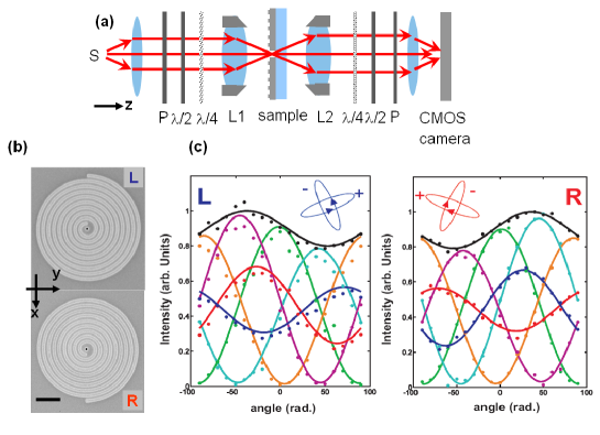
is not relevant here. To increase
this similarity with an usual bull eye antenna the groove depth, and
width were also selected to favor the light coupling to the grating.
Importantly, we also milled a 350 diameter hole centered at the
origin of the spirals (i.e. ) in which light can go through.
Altogether the system acted as a chiral bull eye’s antenna focussing
SPs at the center where they interfere with the incident
light before being transmitted through the hole thanks to a Fano
like mechanism Cyriaque1 ; Cyriaque2 ; Drezet2 ; Yuri2 . Spectral
properties of such antennas showed the typical optical resonance
centered at as for their circular or elliptical
cousins Genet ; Degiron ; Lezec ; Drezet2 .
Chiral optical properties of the two enantiomorphic
structures were studied performing a polarization tomography of the
light transmitted through the hole. The method described in
Ref. Drezet1 ; Drezet2 is based on the experimental
determination of the Mueller
matrix Brehonnet ; Genet2 . Such a Mueller matrix
characterizes the polarization transformation applied on the
incident light beam with Stokes vector
| (174) |
The resultant Stokes vector is
linked to the electric field transmitted through the
hole. Furthermore, subsequent theoretical analysis demonstrate a
precise connection between the Jones matrix
characterizing the system and the Mueller matrix
Brehonnet . We used an home made microscope to focus and
control the state of polarization (SOP) of light going through the
chiral structures. In order to study experimentally the SOP conversion by
our structure, we carried out a complete polarization tomography
using the optical setup sketched in Fig. 3 (a). A laser beam
at nm is focused normally onto the structure by using
an objective L1. The transmitted light is collected by a second
objective L2 forming an Airy spot on the camera as expected since
the hole behaves like a point source in an opaque gold film. In our
experiments, the intensity is thus defined by taking the maximum of
the Airy spot Drezet1 ; Drezet2 . The SOP of light is prepared
and analyzed with half wave plates, quarter wave
plates, and polarizers located before and after the objectives.
To illustrate the polarization conversion induced by the
chiral object on the transmitted light we analyze on Fig. 3 (c) the
transformation acting on a linearly polarized input light analyzed
after transmission in four orthogonal SOP Stokes vectors along the
directions: (green), (yellow),
(cyan), (magenta),
(red), and (blue). The total transmitted
intensity is also shown (black). The symmetries between both panel
expected from group theory are observed experimentally in perfect
agreement with the theory discussed in Ref. Drezet1 . The
insets show in each panel the ellipses of polarization and the
handedness (arrow) associated with the two corotating eingenstates
associated with the Jones matrix. The good agreement between the
measurements and the theoretical predictions deduced from the Jones
matrices Drezet1 is clearly seen, together with the mirror
symmetries between the two enantiomers. This agreement shows that
our theoretical hypothesis about the form of the matrices (see
Eqs. (118,123) is experimentally justified. Importantly, the observed
symmetries also imply that for unpolarized light, and in complete
consistency with spectral studies, the total intensity transmitted
by the structures is
independent of the chosen enantiomer.
IV.2 Chiral surface plasmons and singular optics: tailoring optical vortices
Lately, chiral surface plasmon modes have also been studied in relation to singular optical effects Babiker ; Zhan2009 ; Halas ; Garcia-Vidal . Indeed, near-field excitations on chiral nano structures have shown to generating orbital angular momentum (OAM) both in the near field Ohno ; PRL2008 ; KimNanoLett2010 ; ChoOptX2012 and the far field Nano2009 ; Zhan . We have just recently presented a comprehensive analysis of
the OAM transfer during plasmonic in-coupling and out-coupling by chiral nanostructures at each
side of a suspended metallic membrane, stressing in particular the role of a back-side structure in generating vortex
beams as with tunable OAM indices .
Our device consists of a suspended thin ( nm) metallic membrane, fabricated by evaporating
a metal film over a poly(vinyl formal) resine supported by a transmission electron microscopy
copper grid. After evaporation, the resine is removed using a focused ion-beam (FIB), leaving a
freely suspended gold membrane. Plasmonic structures are milled, in either concentric (BE) or spiral
geometry on both sides of the membrane around a unique central cylindrical aperture acting as
the sole transmissive element of the whole device. The general groove radial path is given in the polar basis,
as , with
an integer, the SP wavelength and a pitch number. Orientation conventions are chosen with respect to the light
propagation direction, so that a right-handed spiral corresponds to and a left-handed spiral
to .
As we summarize below, there is an close relation between the spiral pitch and the topological charge of the vortex generated in the near field.
Near-field generation of OAM at the front-side () of the structured membrane can be understood by considering that each point of the groove illuminated by the incoming
field is an SP point source, launching an SP wave perpendicularly to the groove. With groove widths
much smaller than the illumination wavelength, the in-plane component of the generated SP field in
the vicinity of the center of the structure is where is the Huygens-Fresnel plasmonic propagator and the local unit normal vector determined from the curvature and the arc length of the groove. The resultant SP field is the integral of elementary point sources over the whole groove structure. As indicated by a full evaluation, we can conveniently limit the integration to radial regions where the grooves become pratically annular. This leads to and therefore to a simple expression of the integrated SP field , connected to the incoming field by an in-coupling matrix
| (175) |
the symbol denoting a dyadic product.
Contrasting with the recent studies that have been confined to the near field, our suspended membrane opens the possibility to decouple the singular near field into the far field, with an additional structure on the back-side of the membrane connected to the front-side by the central hole. By symmetry (assuming loss-free unitarity) the out-coupling matrix is simply given as the hermitian conjugate of the in-coupling matrix, i.e.
, corresponding to a surface field that propagates away
from the central hole on the back-side. The in – out-coupling sequence corresponds to the product which, in the circular polarization basis, writes explicitly as
| (176) |
with radial functions based on products of -order Bessel functions of the first kind, as detailed in Gorodetskisub . Note that we use here circular basis conventions that allow associating a positive value to an OAM induced on a right right spiral. With respect to this chapter, these conventions are such that is associated with .
This expression (176) reveals two contributions: a polarization dependent geometric phase, within the matrix, that stems from the spin-orbit coupling at the annular groove, and a factorized dynamic phase that arises due to the spiral twist of the structure PRL2008 . In relation to what has just been described above, the structure of Eq. (176) shows that, it would belong to the general class of chiral structure, as it is not a mere 2D chiral structure, as seen from the fact that nor does it belong to the simple optical activity class given that . Obviously when , the system is achiral and in this case, describes a pure spin–orbit angular momentum transfer, conserving the total angular momentum PRL2008 ; Marucci ; Brasselet ; Manu .
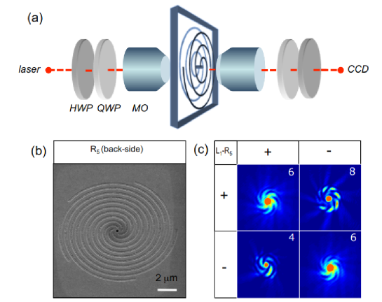
We have checked experimentally the OAM summation rules that can be drawn from this analysis and that can be gathered in a summation table. A sketch of the experiment is presented in Fig. 4. As also shown in panel (c) of the figure, we have been able to generate optical beams in the far field with OAM indices up to , in perfect agreement with the expected OAM summation rules. Note that this value is in strict relation with the chosen structures and is not a limit to our device.
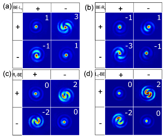
Remarkably with suspended membranes, one can actually perform experimentally the path reversal operation described in section III.5 and in Fig. 2. By merely flipping the BE- structures with respect to the optical axis, one obtains -BE, with enantiomorphic changes generated by the planar character of the spirals milled on one side of the membrane.
As displayed in Fig.5 when comparing panels (a) and (c) and (b) and (d), the OAM measurements however turn out to be inconsistent with a simple path reversal operation. As we fully explain in Gorodetskisub , this discrepency points to the pivotal role of the central aperture in the process of OAM conservation, inducing specific OAM selection rules that must be accounted for in the generation process. This discussion is beyond the scope of this summary, and we refer the reader to our manuscript for further details.
V Outlook
We have tried in this chapter to given an overview on the close relation between the chiral behavior of optical media and reciprocity. This relation has raised recently interesting issues, particularly salient in the context of metamaterial optics. As we discussed here, an algebraic approach can be useful as it allows distinguishing different classes of chiral media with respect to reciprocity. Along these lines, one is naturally led to unveil new types of chiroptical behaviors such as optical planar chirality, a totally original optical signature that contrasts with standard optical activity. Doing so, we have also stressed how reciprocity should not be confused with time-reversal invariance. A couple of recent experimental examples have been presented that nicely illustrate these intertwined relations in the realm of nanophotonics, both in terms of polarization dynamics and optical vortices.
VI Acknowledgments
The authors are grateful to T. W. Ebbesen for his continuous support and Y. Gorodetski, J.-Y. Laluet, and E. Lombard for their participation in the work described here. This work received the financial support of the ERC (grant 227557).
References
- (1) L. D. Landau, E. M. Lifshitz, L. P. Pitaevskii, Electrodynamics of continuous media ed. (Pergamon, New York, 1984).
- (2) F. I. Fedorov, “On the theory of optical activity in crystals I. The law of conservation of energy and the optical activity tensors,” Optics and Spectroscopy 6, 49-53 (1959).
- (3) E. Hecht, Optics ed. (Addison-Wesley, Massachusetts, 1987).
- (4) S. F. Masson, Chemical evolution: Origins of the elements, molecules and living systems pp. 281-284 (Clarendon Press, Oxford, 1991).
- (5) T. D. Lee and C. N. Yang, “ Question of parity conservation in weak interactions,” Phys. Rev. 104, 254 258 (1956)
- (6) I. Kant, Prolegomena to any future metaphysics (1783) (reissued by Hacket Publishing, 1977).
- (7) W. Thomson (L. Kelvin),Baltimore Lectures on Molecular Dynamics and the Wave Theory of Light (1904) (reissued by Cambridge University Press, 2010).
- (8) M. Faraday, “Experimental Researches in Electricity. Nineteenth Series”, Phil. Trans. R. Soc. Lond. 136, 1-20 (1846).
- (9) D. -F. M. Arago,“Mémoire sur une modification remarquable qu’éprouvent les rayons lumineux dans leur passage à travers certains corps diaphanes, et sur quelques autres nouveaux phénomènes d’optique,” Mém. Inst. France, Part I 12 (1811).
- (10) J. B. Biot, “Sur un nouveau genre d’oscillations que les molécules de la lumière éprouvent en traversant certains cristaux”, Mém. Inst. Nat. Sci. Art. 13, 1. (1812).
- (11) A. Fresenel, “Mémoire sur la double réfraction,” presented at the Académie des sciences the 9 th December 1822). See also Vol. 1 S. Verdet and L. Fresnel, œuvres complètes d’Augustin Fresnel (Imprimerie impériale, Paris, 1866).
- (12) L. Pasteur, “Mémoire sur la relation qui peut exister entre la forme cristalline et la composition chimique, et sur la cause de la polarization rotatoire,” C. R. Acad. Sci. Paris 26, 535-539 (1848).
- (13) H. D. Flack, “Louis Pasteur discovery of molecular chirality and spontaneous resolution in 1848, together with complete review of his crystallographic and chemical work,” Act. Cryst. A 65, 371-389 (2009).
- (14) J. A. Le Bel, “Sur les relations qui existent entre les formules atomiques des corps organiques et le pouvoir rotatoires de leru dissolutions,” Bull. Soc. Chim. Fr. 22, 1874, 337 347.
- (15) J. H. van’t Hoff, “Sur les formules de structures dans l’espace,” Arch. Neerl. Sci. Exactes,” 9, 445-454 (1874).
- (16) A. Cotton, “Absorption in gale des rayons circulaires droit et gauche dans certains corps actifs”, Compt. Rend. 120, 989-991 (1895) and “Dispersion rotatoire anomale des corps absorbants”, Compt. Rend. 120, 1044-1046 (1895).
- (17) J. C. Bose, “On the rotation of plane of polarization of electric waves by a twisted structure.” Proc. R. Soc. London A 63, 146-152 (1898).
- (18) K.F. Lindman, Ann. Physik 63, 621 (1920). For a review see I. V. Lindell, A. H. Sihvola, and J. Kurkijarvi, ”Karl F. Lindman: The last Hertzian, and a harbinger of electromagnetic chirality”. IEEE Antennas and Propagation Magazine 34, 24-30 (1992).
- (19) I. Tinoco and M. P. Freeman, “The optical activity of oriented copper helices. I. Experimental,” J. Phys. Chem. 61, 1196-1200 (1957).
- (20) J. B. Pendry, “A chiral route to negative refraction,” Science 306, 1353-1355 (2004).
- (21) A. Papakostas, A. Potts, D. M. Bagnall, S. L. Prosvirnin, H. J. Coles and N. I. Zheludev, “Optical manisfestation of planar chirality,” Phys. Rev. Lett. 90, 107404 (2003).
- (22) A. S. Schwanecke, A. Krasavin, D. M. Bagnall, A. Potts, A. V. Zayats and N. I. Zheludev, “Broken time symmetry of light interaction with planar chiral nanostructures,” Phys. Rev. Lett. 91, 247404 (2003).
- (23) T. Vallius, K. Jefimovs, J. Turunen, P. Vahimaa and Y. Svirko, “Optical activity in subwalength-period arrays of chiral metallic particles,” Appl. Phys. Let. 83, 234-236 (2003).
- (24) M. Kuwata-Gonokami, N. Saito, Y. Ino, M. Kauranen, K. Jefimovs, T. Vallius, J. Turunen and Y. Svirko, “Giant optical activity in quasi-two-dimensional planar nanostructures,” Phys. Rev. Lett. 95, 227401 (2005).
- (25) B. K. Canfield, S. Kujala1, K. Jefimovs, J. Turunen and M. Kauranen, “Linear and nonlinear optical responses influenced by broken symmetry in an array of gold nanoparticles,” Opt. Express 12, 5418-5423 (2004).
- (26) B. K. Canfield, S. Kujala1,K. Laiho1, K. Jefimovs, J. Turunen and M. Kauranen, “Remarkable polarization sensitivity of gold nanoparticle arrays,” Opt. Express 12, 5418-5423 (2004).
- (27) W. Zhang, A. Potts, A. Papakostas and D. M. Bagnall, “Intensity modulation and polarization rotation of visible light by dielectric planar chiral materials,” Appl. Phys. Lett. 86, 231905 (2005).
- (28) M. Decker, M. W. Klein, M. Wegener and S. Linden, “Circular dichroism of planar chiral magnetic metamaterials,” Opt. Lett. 32, 856-858 (2007).
- (29) E. Plum, V. A. Fedotov, A. S. Schwanecke, N. I. Zheludev and Y. Chen “Giant optical gyrotropy due to electromagnetic coupling,” Appl. Phys. Lett. 90, 223113 (2007).
- (30) A. V. Rogacheva, V. A. Fedotov, A. S. Schwanecke and N. I. Zheludev, “Giant gyrotropy due to electromagnetic-field coupling in a bilayered chiral structure.” Phys. Rev. Lett. 97, 177401 (2006).
- (31) S. L. Prosvirnin and N. I. Zheludev,“Polarization effects in the diffraction of light by planar chiral structure”, Phys. Rev. E 71, 037603 (2005).
- (32) A. Krasavin, A. S. Schwanecke and N. I. Zheludev, J. Opt. A: Pure Appl. Opt. 8, S98-S105 (2006).
- (33) M. Reichelt, S. W. Koch, A. Krasavin, J. V. Moloney, A. S. Schwanecke, T. Stroucken, E. M. Wright and N. I. Zheludev, “Broken enantiomeric symmetry for electromagnetic waves interacting with planar chiral nanostructures”, Appl. Phys. B 84, 97-101 (2006).
- (34) J. K. Gansel, M. Thiel, M. S. Rill, M. Decker, K. Bade, V. Saile, G. von Freymann, S. Linden, M. Wegener,“Gold helix photonic metamaterial as broadband circular polarizer,” Science 325, 1513-1515 (2009).
- (35) C. M. Soukoulis and M. Wegener, “Past achievements and futur challenges in the development of three-dimensional photonic metamaterials,” Nature Photon. 5 , 523-530 (2011).
- (36) Y. Zhao, M.A. Belkin, A.Alù, “Twisted optical metamaterials for planarized ultrathin broadband circular polarizers,” Nature Commun. 3, Article number:870 [doi:10.1038/ncomms1877] (2012).
- (37) N. I. Zheludev, “The road ahead for metamarials,” Science 328, 582-583 (2010).
- (38) H. A. Lorentz, “The theorem of Poynting concerning the energy in the electromagnetic field and two general propositions concerning the propagation of light,” Amsterdammer Akademie der Wetenschappen 4, 176 (1896).
- (39) R. Carminati, M. Nieto-Vesperinas, J. -J. Greffet, “Reciprocity of evanescent electromagnetic waves,” J. Opt. Soc. Am. A 15, 706-712 (1997).
- (40) L. Hecht, L. D. Barron, “Rayleigh and Raman optical activity from chiral surfaces,” Chem. Phys. Lett. 225, 525-530 (1994).
- (41) L. D. Barron, “Parity and optical activity,” Nature 238, 17-19 (1972).
- (42) V. A. Fedotov, P. L. Mladyonov, S. L. Prosvirnin, A. V. Rogacheva, Y. Chen and N. I. Zheludev, “Asymmetric propagation of electromagnetic waves through a planar chiral structure,” Phys. Rev. Lett. 97, 167401 (2006).
- (43) V. A. Fedotov, A. S. Schwanecke, N. I. Zheludev, V. V. Khardikov and S. L. Prosvirnin, “Asymmetric transmission of light and enantiomerically sensistive plasmon resonance in planar chiral nanostructures,” Nano Lett. 7, 1996-1999 (2007).
- (44) W. L. Barnes, A. Dereux, T. W. Ebbesen, “Surface plasmon subwavelength optics,” Nature 424, 824 (2003).
- (45) C. Genet, T. W. Ebbesen, “Light in tiny holes,” Nature 445, 39-46 (2007).
- (46) L. Novotny, and B. Hecht, Principles of Nano-Optics (Cambridge Press, London, 2006).
- (47) A. S. Schwanecke, V. A. Fedotov, V. V. Khardikov, S. L. Prosvirnin, Y. Chen and N. I. Zheludev, “Asymmetric transmission of light and enantiomerically sensistive plasmon resonance in planar chiral nanostructures,” Nano Lett. 8, 2940-2943 (2008).
- (48) A. Drezet, C. Genet, J.-Y. Laluet, and T. W. Ebbesen, “Optical chirality without optical activity: How surface plasmons give a twist to light,” Opt. Express 16, 12559-12570 (2008).
- (49) Y. Gorodetski, A. Drezet, C. Genet, and T. W. Ebbesen, “Generating far-field orbital angular momenta from near-field chirality”, submitted (2012).
- (50) H. B. G. Casimir, “On Onsager’s Principle of Microscopic Reversibility”, Rev. Mod. Phys. 17, 343-350 (1945).
- (51) L.R. Arnaut, “ Chirality in multi-dimensional space with application to electromagnetic characterization of multi-dimensionnal chiral and semi chiral media,” J. Electromagn. Waves Appl. 11, 1459-1482 (1997).
- (52) M. A. Osipov, B. T. Pickup, M. Fehervari, and D. A. Dunmur, “Chirality measure and chiral order parameter for a two dimensionnal system,” Mol. Phys. 94, 283-287 (1998).
- (53) C. W. Bunn, Chemical Crystallography (Oxford University Press, New York, 1945).
- (54) E. Plum, V. A. Fedotov, N. I. Zheludev,“Extrinsic electromagnetic chirality in metamaterials,” J. Opt. A: Pure Appl. Opt. 11, 074009 (2009).
- (55) B. M. Maoz, A. Ben Moshe, D. Vestler, O. Bar-Elli, and G. Markovich, “Chiroptical effects in planar achiral plasmonic oriented nanohole arrays”, Nano Lett. 12, 2357-2361 (2012).
- (56) A. Degiron and T. W. Ebbesen, “Analysis of the transmission process through a single aperture surrounded by periodic corrugations,” Opt. Express 12, 3694-3700 (2004).
- (57) H. J. Lezec, A. Degiron, E. Devaux, R. A. Linke, L. Martin-Moreno, F. J. Garcia-Vidal and T. W. Ebbesen, “Beaming light from a subwavelength aperture,” Science 297, 820-822 (2002).
- (58) C. Genet, M. P. van Exter, and J. P.Woerdman, “Huygens description of resonance phenomena in subwavelength hole arrays,” J. Opt. Soc. Am. A 22, 998-1002 (2005).
- (59) C. Genet, M. P. van Exter, and J. P. Woerdman,“Fano-type interpretation of red shifts and red tails in hole arrays transmission spectra,” Opt. Commun. 225, 331-336 (2003)
- (60) A.Drezet, C. Genet and T. W. Ebbesen, “Miniature plasmonic wave plates,” Phys. Rev. Lett. 101, 043902 (2008).
- (61) Y. Gorodetski, E. Lombard, A. Drezet, C. Genet, T. W. Ebbesen, “A perfect plasmonic quarter-wave plate,” Appl. Phys. Lett. 101, 201103 (2012).
- (62) F. Le Roy-Brehonnet, B. Le Jeune, “Utilization of Mueller matrix formalism to obtain optical targets depolarization and polarization properties,” Prog. Quant. Electr. 21, 109-151 (1997).
- (63) C. Genet, E. Altewischer, M. P. van Exter and J. P. Woerdman, “Optical depolarization induced by arrays of subwavelength metal holes,” Phys. Rev. B. 71, 033409 (2005).
- (64) V. E. Lembessis, M. Babiker, and D. L. Andrews, “Surface optical vortices”, Phys. Rev. A 79, 011806-011809 (2009).
- (65) S. Yang, W. Chen, R. L. Nelson, and Q. Zhan, “Miniature circular polarization analyzer with spiral plasmonic lens”, Opt. Lett. 34, 3047-3049 (2009).
- (66) S. Zhang, H. Wei, K. Bao, U. Håkanson, N. J. Halas, P. Nordlander, and H. Xu, “Chiral surface plasmon polaritons on metallic nanowires”, Phys. Rev. Lett. 107, 096801-096804 (2011).
- (67) F. Rüting, A. I. Fernández-Domínguez, L. Martín-Moreno, and F. J. García-Vidal, “Subwavelength chiral surface plasmons that carry tuneable orbital angular momentum”, Phys. Rev. B 86, 075437-075441 (2012).
- (68) T. Ohno and S. Miyanishi, “Study of surface plasmon chirality induced by Archimedes’ spiral grooves”, Opt. Express 14, 6285-6290 (2007).
- (69) Y. Gorodetski, A. Niv, V. Kleiner, and E. Hasman, “Observation of the spin-based plasmonic effect in nanoscale structures”, Phys. Rev. Lett. 101, 043903-043906 (2008).
- (70) H. Kim , J. Park , S.-W. Cho , S.-Y. Lee , M. Kang, and B. Lee, “Synthesis and Dynamic Switching of Surface Plasmon Vortices with Plasmonic Vortex Lens”, Nano Lett. 10, 529-536 (2010).
- (71) S.-W. Cho, J. Park, S.-Y. Lee, H. Kim, and B. Lee, “Coupling of spin and angular momentum of light in plasmonic vortex”, Opt. Express 20, 10083-10094 (2012).
- (72) Y. Gorodetski, N. Shitrit, I. Bretner, V. Kleiner, and E. Hasman, “Observation of Optical Spin Symmetry Breaking in Nanoapertures”, Nano Lett. 9, 3016-3019 (2009).
- (73) G. Rui, R. L. Nelson, and Q. Zhan, “Circularly polarized unidirectional emission via a coupled plasmonic spiral antenna”, Opt. Lett. 36, 4533-4535 (2011).
- (74) L. Marrucci, C. Manzo, and D. Paparo, “Optical spin-to-orbital angular momentum conversion in inhomogeneous anisotropic media”, Phys. Rev. Lett. 96, 163905-163908 (2006).
- (75) E. Brasselet, N. Murazawa, H. Misawa, and S. Juodkazis, “Optical vortices from liquid crystal droplets”, Phys. Rev. Lett. 103, 103903-103906 (2009).
- (76) E. Lombard, A. Drezet, C. Genet, and T. W. Ebbesen, “Polarization control of non-diffractive helical optical beams through subwavelength metallic apertures”, New J. Phys. 10, 023027-023039 (2010).