3D Object Reconstruction from Hand-Object Interactions
Abstract
Recent advances have enabled 3d object reconstruction approaches using a single off-the-shelf RGB-D camera. Although these approaches are successful for a wide range of object classes, they rely on stable and distinctive geometric or texture features. Many objects like mechanical parts, toys, household or decorative articles, however, are textureless and characterized by minimalistic shapes that are simple and symmetric. Existing in-hand scanning systems and 3d reconstruction techniques fail for such symmetric objects in the absence of highly distinctive features. In this work, we show that extracting 3d hand motion for in-hand scanning effectively facilitates the reconstruction of even featureless and highly symmetric objects and we present an approach that fuses the rich additional information of hands into a 3d reconstruction pipeline, significantly contributing to the state-of-the-art of in-hand scanning.
1 Introduction
The advent of affordable RGB-D sensors has opened up a whole new range of applications based on the 3d perception of the environment by computers, which includes the creation of a virtual 3d representation of real objects. A moving camera can navigate in space observing the real world, while incrementally fusing the acquired frames into a 3d virtual model of it. Similarly, a static camera can observe a scene and dynamically reconstruct the observed moving objects. This domain has attracted much interest lately in the computer vision, the graphics and the robotics (SLAM) community, as it enables a plethora of other applications, facilitating among others 3d object detection, augmented reality, the internet of things, human-computer-interaction and the interaction of robots with the real world.
The field has matured [30] since its beginning in the early 80s [19] and during the 90s [2, 3, 25, 5]. Nowadays, several commercial solutions for 3D scanning with an off-the-shelf RGB-D camera have appeared, e.g., Fablitec [31], Skanect111http://skanect.occipital.com/, iSense222http://cubify.com/products/isense, KScan3d333http://www.kscan3d.com/, Shapify [16] and Kinect-Fusion [22]. Several open-source projects like KinFu address the same problem, while other commercial solutions as MakerBot-Digitizer employ a laser scanning device along with sensorimotor information from a turntable.
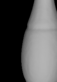
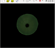
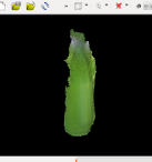
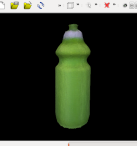
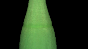
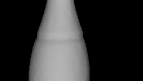
Instead of a turntable, an object can also be rotated by hand in case of a static camera. This setting is very convenient for hand-sized objects since moving an object is more practical than moving a camera with a cable. Such a setup is also called in-hand scanning [28]. Weise et al. presented a real-time in-hand scanning system [37] that was later augmented with online loop closure [38]. Although the results are very convincing, the method uses the hand only as a replacement of a turntable and discards the hand information. When the objects are textureless and contain very few geometric features, the in-hand scanning fails as illustrated in Figure 1.
In this work, we propose to use the hand motion for in-hand scanning as an additional cue to reconstruct also texturless objects. Instead of discarding the hands with the use of a black glove [38], we track the hand pose and use the captured hand motion together with texture and geometric features for object reconstruction as in Figure 3. Since the hand motion provides additional information about the object motion, we can reconstruct even textureless and symmetric objects as shown in Figure 1.
2 Related work
During the last decades several real-time in-hand scanning systems like [28, 37, 38] have been presented. Such systems are able to provide a real-time registration of the input frames, while the interactivity enables the user to guide the reconstruction process. Assuming high temporal continuity and objects with rich geometric features, the quality of the final reconstruction can be sufficient. Some methods add an offline optimization step [25] to solve the loop closure problem, but in this case the final result might differ from the intermediate result. In order to solve this issue, Weise et al. presented a real-time in-hand scanning system [37] that was later augmented with online loop closure [38]. They follow an as-rigid-as-it-gets approach based on surfels in order to minimize registration artifacts. Due to online loop closure, the approach does not require any post-processing. A different approach is proposed in STAR3D [26]. In this work a 3d level-set function is used to perform simultaneous tracking and reconstruction of rigid objects. Similarly to in-hand scanning, this approach works only for objects with sufficient geometric or texture features. In order to reconstruct textureless and symmetric objects, additional information from sensors, markers [21], or a robotic manipulator is required [12, 13].
In this work, we propose to extract the additional information directly from the hand within an in-hand scanning framework. Instead of simply discarding the hand [28, 37, 38], we capture the hand motion. In recent years, there has been a progress in hand motion capture. In particular, capturing of hand-object interactions has become of increasing interest [27, 9, 8, 23, 14, 1]. These approaches assume that a model of the object is given, while we aim to reconstruct the object during hand-object interactions. In [20] a rigid tool is tracked in a multicamera setup to reconstruct textureless and even transparent objects. Shape carving is in this case explicitly performed by the tool and the tool needs to be swept over the entire objects, which can be time-consuming. In contrast to in-hand scanning, this approach needs an additional tool. Static objects have also been used in [29] to augment a SLAM system with the pose of repetitive objects in a scene.
3 Hand motion capture for in-hand scanning
As illustrated in Figure 3, we observe an RGB-D video where a hand is interacting with an object. The data is first preprocessed as described in Section 3.1 and the hand pose is estimated in each frame as described in Section 3.2. We then exploit the captured hand motion to reconstruct the object as shown in Figure 1. The reconstruction process is described Section 4.
3.1 Preprocessing
We first remove irrelevant parts of the RGB-D image by thresholding the depth values in order to avoid unnecessary processing like normal computation for distant points. To this end, we keep only points within a specified volume. For the used Primesense Carmine 1.09 sensor, only points within the volume are kept. Subsequently we apply skin color segmentation on the RGB image using the Gaussian-Mixtures-Model (GMM) of [10] and get the masked RGB-D images for the object and for the hand.
3.2 Hand motion capture
In order to capture the motion of a hand, we employ an approach similar to [35]. The approach uses a hand template mesh and parameterizes the hand pose by a skeleton and linear blend skinning [15]. For pose estimation, we minimize an objective function, which consists of three terms:
| (1) | ||||
where is the current preprocessed depth image for the hand and are the pose parameters of the hand. The first two terms of Equation (1) minimize the alignment error between the input depth data and the hand pose. The alignment error is measured by , which measures how well the model fits the observed depth data, and , which measures how well the depth data is explained by the model. penalizes intersections of fingers and enhances realism by ensuring physically plausible poses. The parameter is set to as in [35]. For simplicity we do not use the additional term of [35] for the detected salient points. The overall hand tracking accuracy for the hand joints is approximately .
4 Object reconstruction
In order to use the captured hand motion for 3D reconstruction, we have to infer the contact points with the object. This is described in Section 4.1. The reconstruction process based on the estimated hand poses and the inferred contact points is then described in Section 4.2.
4.1 Contact Points Computation
In order to compute the contact points, we use the high-resolution mesh of the hand, which has been used for hand motion capture. To this end, we compute for each vertex associated to each end-effector the distance to the closest point of the object point cloud . We first count for each end-effector the number of vertices with a closest distance of less than . If an end-effector has more than candidate contact vertices, it is labeled as a contact bone and all vertices of the bone are labeled as contact vertices. If there are not at least 2 end-effectors selected, we iteratively increase the distance threshold by until we have at least two end-effectors. In our experiments, we observed that the threshold barely exceeds . As a result, we obtain for each frame pair the set of contact correspondences , where is a pair of contact vertices in the source and target frame, respectively. Figure 3 depicts the contact correspondences for a frame pair.
4.2 Reconstruction
We use a feature-based approach for reconstruction, where we first align the currently observed point cloud (source) to the previous frame (target) and afterwards we align the transformed source by ICP to the previously accumulated transformed point cloud [4] for refinement.
For pairwise registration, we combine features extracted from and the contact points, which have been extracted from and the hand pose . As a result, we minimize an energy function based on two weighted energies:
| (2) | ||||
where is a measure of the discrepancy between the incoming and the already processed data, that needs to be minimized. In that respect, we seek the rigid transformation , where is a rotation matrix and is a translation vector, that minimizes the energy by transforming the source frame accordingly.
The visual energy consists of two terms that are computed on the visual data of the object point cloud :
| (3) | ||||
The term is based on a sparse set of correspondences using SIFT [18] features that are back-projected in by the function : , given the intrinsic parameters of the camera. The SIFT keypoint correspondences in the source and target image respectively are denoted as , while and are the corresponding back-projected points. is then formulated as
| (4) | ||||
In a similar manner, the term is based on a sparse set of correspondences . Instead of the image domain, we operate on the point cloud by choosing ISS3D [39] keypoints and the CSHOT [33] feature descriptor, that augments the SHOT [32] descriptor with texture information. This combination has been shown to work well for point clouds [6, 34]. is then formulated as
| (5) | ||||
Finally, the term depends on the current hand pose estimate and the hand point cloud . Based on these, the contact correspondences are computed as described in Section 4.1. Let be the corresponding contact points, i.e. vertices, in the source and target frame respectively, then is written as
| (6) | ||||
The two terms in the energy function (2) are weighted since they have different characteristics. Although visual correspondences preserve local geometric or textural details better, they tend to cause a slipping of one frame upon another in case of textureless and symmetric objects. In this case, the contact correspondences ensure that the movement of the hand is taken into account. An evaluation of the weight is presented in Section 5.
The sparse correspondence sets , , and provide usually an imperfect alignment of the source frame to the target frame either because of noise, ambiguities in the visual features or the pose, or a partial violation of basic assumptions like the rigid grasping of an object during interaction. For this reason, we refine the aligned source frame by finding a locally optimal solution based on dense ICP [2] correspondences. While for the sparse correspondences we align the current frame only to the previous one, during this refinement stage we align the current frame to the accumulation of all previously aligned frames [4], i.e. the current partial reconstructed model. After finding a dense set of ICP correspondences with maximum distance of mm, we minimize the discrepancy between them
| (7) | ||||
4.2.1 Surface model
To obtain a mesh representation of the reconstructed object, we first employ a truncated signed distance function (TSDF) [5, 22] to get a volumetric representation. The TSDF volume has a dimension of for all objects with voxel resolution and maximum voxel size. Subsequently we apply the marching-cubes [17] method to extract a mesh and remove tiny disconnected components. The final mesh is then obtained by Laplacian smoothing [36] followed by Poisson reconstruction [11] with an octree with layers in order to get a smooth, water-tight mesh with preserved details.
5 Experiments
In this section we show that although existing in-hand scanning pipelines fail for symmetric and textureless objects, the incorporation of hand motion capture can effectively improve the reconstruction, enabling the efficient and full reconstruction of such objects without the use of additional intrusive markers or devices in the scene. We present thus for the first time the effective reconstruction of symmetric objects with an in-hand scanning system, which cannot be reconstructed by two state-of-the-art reconstruction systems. Furthermore, we perform an experiment with synthetic data, showing that the pipeline can also be applied to multicamera RGB videos.
The recorded sequences, calibration data, hand motion data, as well as video results, the resulting meshes and the source code for reconstruction are publicly available444http://files.is.tue.mpg.de/dtzionas/ihScanning.


| Dimensions Comparison | G.Truth | Ours | KinFu (*) | Skanect (*) | Detect.Baseline | Enriched Texture | |||||||||||||
| Capture | Diff. | Capture | Diff. | Capture | Diff. | Capture | Diff. | Capture | Diff. | ||||||||||
| Water-bottle diameter | mm | ||||||||||||||||||
| Water-bottle height | |||||||||||||||||||
| Bowling-pin head diameter | |||||||||||||||||||
| Bowling-pin body diameter | |||||||||||||||||||
| Bowling-pin height | |||||||||||||||||||
| Small-bottle diameter | |||||||||||||||||||
| Small-bottle height | |||||||||||||||||||
| Sphere diameter | |||||||||||||||||||
| Average | |||||||||||||||||||
| Sphere volume | |||||||||||||||||||
5.1 Synthetic data
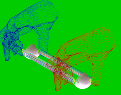
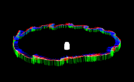
In order to generate synthetic data we use the publicly available555http://cvg.ethz.ch/research/ih-mocap data of a multicamera RGB hand tracker [1]. We use the frames - of the sequence in which a hand interacts with a rigid ball. We generate synthetic point clouds by rendering the moving meshes. We then apply the pipeline described in Section 4 to the rendered point clouds and use the hand meshes and motion data of [1].
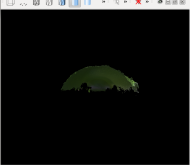
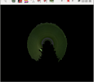
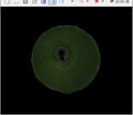
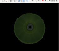
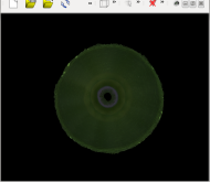
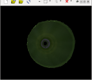
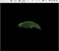
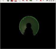
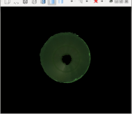
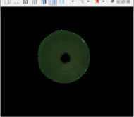
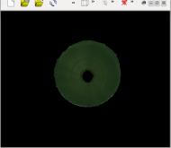
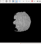
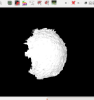
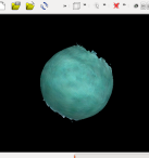
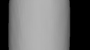
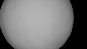
The resulting accumulated and aligned point cloud is depicted in Figure 4. Figure 4(a) shows the reconstruction without hand motion data, while Figure 4(b) shows the reconstruction after the incorporation of hand motion into the in-hand scanning system. The reconstruction without the hand motion data collapses to a degenerate hemisphere, while it is clear that the hand motion data significantly contributes towards the effective reconstruction of the manipulated object. Parts of the object are never visible in the sequence. The occlusions caused by the manipulating fingers can be clearly observed, verifying the correct registration of the camera frames.
5.2 Realistic data
For our experiments with realistic data, we use a Primesense Carmine 1.09 short-range, structured-light RGB-D camera. Structured light sensors may not be optimal for hand pose estimation, in contrast to time-of-flight sensors, because significant parts of the hand completely disappear from the depth image in case of reflections or at some viewing angles. Nevertheless, the used hand tracker worked well with the sensor.
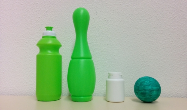
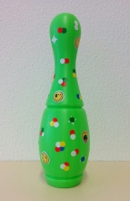
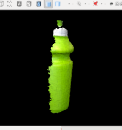
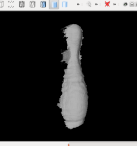
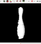
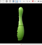
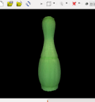
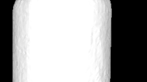
In order to perform both a qualitative and a quantitative evaluation, we have captured new sequences for the four objects depicted in Figure 5. As seen in Table 1, the size of the objects varies in order to be representative of several everyday objects. However, all objects have in common the high symmetry and the lack of distinctive geometrical and textural features, that renders them especially challenging for existing in-hand scanning systems.
In the following we show the successful reconstruction of these objects for the first time with an in-hand scanning system, while we systematically evaluate the performance of our pipeline both with respect to existing baselines, ground-truth object dimensions as well as state-of-the-art systems.
5.2.1 Quantitative evaluation
Acquiring a ground-truth measure is difficult for most objects, however, for symmetric ones it is easy to measure the dimensions of some distinctive areas. We therefore measure manually the distinctive dimensions of the objects depicted in Figure 5 in order to quantitatively evaluate the proposed setup. The ground-truth dimensions, along with the measured ones by our approach and the measurement error, are presented in Table 1. Especially for the case of the sphere, we can easily acquire a ground truth value for its volume, that is less prone to measurement errors introduced by human factors.
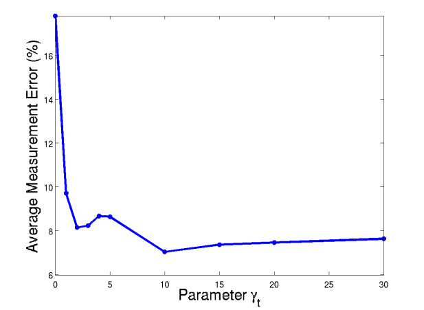
During quantitative evaluation, we measured the distinctive dimensions of the water-tight meshes that are reconstructed by our pipeline. We then evaluate the most important parameter of our pipeline, namely the weight that steers the influence of the contact correspondences in the in-hand scanning system. The results of our experiments are summarized in Figure 6, which plots the mean accumulated estimation errors of the eight parameters normalized by the ground-truth values, i.e., . Without the contact correspondences and using only visual features (), the error is relatively high since the reconstruction for symmetric objects fails in this case. Even small values for result in an abrupt drop in the error metric, however, the influence of the contact correspondences starts becoming more apparent for values above . In all subsequent experiments, we use .
The performance of our setup is described in more details in Table 1 which provides a direct comparison to the measured object dimensions. The average error is only , comparable to the noise of commodity RGB-D sensors, showing the potential of such a system for a wide range of everyday applications.
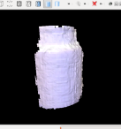
For evaluation against a reference reconstructed shape, we also add textural features on the bowling-pin in the form of stickers, as depicted in Figure 7, without altering the geometrical shape of the object. We then perform the reconstruction by rotating the object on a turntable. The resulting reconstruction is illustrated in Figure 7, while quantitative measures are provided for comparison in Table 1.
We further test the effectiveness of our system in comparison to two state-of-the-art systems, namely KinFu666http://pointclouds.org/documentation/tutorials/using_kinfu_large_scale.php, an open-source implementation of Kinect-Fusion [22], and the similar commercial system Skanect777http://skanect.occipital.com. For technical reasons, we use KinFu with a Kinect and Skanect with the Structure-IO camera. Existing in-hand scanning approaches are expected to have a performance similar to these systems. For comparison, we use KinFu and Skanect to reconstruct the four objects depicted in Figure 5. A turntable rotates each object for approximately degrees in front of a static camera, while we repeat the process three times and report only the best run in order to assure objectiveness. Quantitative performance measures are provided for these methods in Table 1.
In order to show the important role of the hand pose in our reconstruction pipeline, we replace the contact correspondences based on contact vertices with correspondences based on a contact detector. In that respect we train a Hough forest [7] detector that detects finger-object contacts in RGB images. We then establish correspondences between the points enclosed by the detection bounding boxes in the source and target frames simply by associating points with the same 2d coordinates inside the fixed-sized bounding boxes. In that respect, the term in the objective function (2) is replaced by the term
| (8) | ||||
The results of the reconstruction, depicted in Figure 5.2.2, show that the reconstruction is either incomplete or it has major flaws, which is supported by the numbers in Table 1.
In order to measure the accuracy of the contact correspondences obtained by the hand pose or the contact detector, we manually annotated two points for each of the two manipulating fingers for pairs of consecutive frames and we do so for every 10th frame in our four sequences. We then measure the pairwise registration error for each annotated pair by . The results are summarized in Table 2 and show that the hand tracker is more accurate for pairwise registration than a detection based approach.
5.2.2 Qualitative evaluation


| Energy | mean | st.dev. | |||
|---|---|---|---|---|---|
| + | mm | ||||
| + | |||||
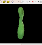
Although the quantitative evaluation is informative, a qualitative evaluation can give further intuition about the effectiveness of the system and the influence of its parameters. We therefore show in Figure 5.2.1 the mesh extracted from the TSDF volume of our pipeline for a number of different values for the weight . The experiment is done for the two objects where the influence of can be easily observed visually. As expected, the reconstruction without the use of hand motion capture results in a degenerate alignment. The incorporation of contact correspondences immediately improves the reconstruction, driving the alignment process according to the spatiotemporal movement of the contact fingers. A low value, however, leads only to a partial reconstruction. A sensible choice seems to be a value between and , while for bigger values some small alignment artifacts appear. For our experiments we choose .
While Figure 5.2.2 shows the reconstruction when the hand tracker is replaced by a detector, Figure 10 shows the reconstruction of the bowling-pin when ICP, as described in Equation (7), is not used. In both cases, the point clouds are not well aligned.
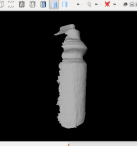
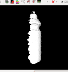
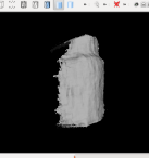
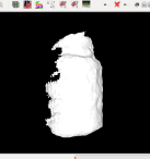
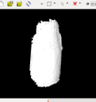
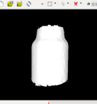
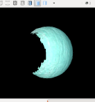
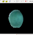
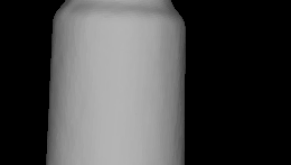
Figure 5.2.2 shows the best reconstruction of three runs by KinFu and Skanect in comparison to our pipeline, both with and without the use of hands and hand motion data. The images show that the reconstruction without hands is similar across different systems and results in a degenerate 3d representation of the object. The incorporation of hand motion capture in the reconstruction plays clearly a vital role, leading to the effective reconstruction of the full surface of the object.
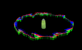
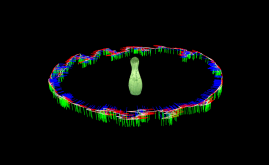
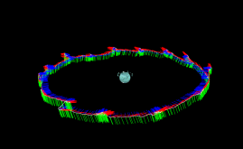
Although Figure 5.2.2 compares the TSDF meshes, more detailed results are shown in Figure 5.2.2. The camera poses are reconstructed effectively, showing not only the rotational movement during the scanning process, but also the type and intensity of hand-object interaction. The water-tight meshes that are shown compose the final output of our system. The resulting reconstruction renders our approach the first in-hand scanning system to cope with the reconstruction of symmetric objects, while also showing prospects of future practical applications.


5.3 Limitations
While our approach does not depend on a specific hand tracker, it only works if the hand tracker does not fail. At the moment only end-effectors are considered, therefore cases where there is only contact with the palm are not handled, but the approach can be extended to more general contact points. Moreover the case of fingers slipping over the manipulated object is not handled currently, but this could be addressed by using a hand tracker that estimates forces [24].
6 Conclusion
While existing in-hand scanning systems discard information originating from the hand, we have proposed an approach that successfully incorporates the 3d motion information of the manipulating hand for 3d object reconstruction. In that respect, the visual correspondences based on geometric and texture features are combined with contact correspondences that are inferred from the manipulating hand. In our quantitative and qualitative experiments we show that our approach successfully reconstructs the 3d shape of four highly symmetric and textureless objects.
7 Acknowledgments
We gratefully acknowledge the help of Abhilash Srikantha with the Hough forest detector and Pablo Aponte with KinFu. Financial support was provided by the DFG Emmy Noether program (GA 1927/1-1). Dimitrios Tzionas would like to dedicate this work in the memory of his grandmother Olga Matoula.
References
- [1] L. Ballan, A. Taneja, J. Gall, L. Van Gool, and M. Pollefeys. Motion capture of hands in action using discriminative salient points. In ECCV, 2012.
- [2] P. Besl and N. D. McKay. A method for registration of 3-d shapes. PAMI, 1992.
- [3] G. Blais and M. D. Levine. Registering multiview range data to create 3d computer objects. PAMI, 1995.
- [4] Y. Chen and G. Medioni. Object modeling by registration of multiple range images. In ICRA, 1991.
- [5] B. Curless and M. Levoy. A volumetric method for building complex models from range images. In SIGGRAPH, 1996.
- [6] S. Filipe and L. A. Alexandre. A comparative evaluation of 3d keypoint detectors. In Conference on Telecommunications, 2013.
- [7] J. Gall, A. Yao, N. Razavi, L. Van Gool, and V. Lempitsky. Hough forests for object detection, tracking, and action recognition. PAMI, 33(11):2188–2202, 2011.
- [8] H. Hamer, J. Gall, T. Weise, and L. Van Gool. An object-dependent hand pose prior from sparse training data. In CVPR, 2010.
- [9] H. Hamer, K. Schindler, E. Koller-Meier, and L. Van Gool. Tracking a hand manipulating an object. In ICCV, 2009.
- [10] M. J. Jones and J. M. Rehg. Statistical color models with application to skin detection. IJCV, 46(1):81–96, 2002.
- [11] M. Kazhdan, M. Bolitho, and H. Hoppe. Poisson surface reconstruction. In SGP, 2006.
- [12] D. Kraft, N. Pugeault, E. Başeski, M. popovicć, D. Kragić, S. Kalkan, F. Wörgötter, and N. Krüger. Birth of the object: detection of objectness and extraction of object shape through object–action complexes. International Journal of Humanoid Robotics, 2008.
- [13] M. Krainin, P. Henry, X. Ren, and D. Fox. Manipulator and object tracking for in-hand 3d object modeling. IJRR, 30(11):1311–1327, 2011.
- [14] N. Kyriazis and A. Argyros. Physically plausible 3d scene tracking: The single actor hypothesis. In CVPR, 2013.
- [15] J. P. Lewis, M. Cordner, and N. Fong. Pose space deformation: A unified approach to shape interpolation and skeleton-driven deformation. In SIGGRAPH, 2000.
- [16] H. Li, E. Vouga, A. Gudym, L. Luo, J. T. Barron, and G. Gusev. 3d self-portraits. SIGGRAPH Asia, 2013.
- [17] W. E. Lorensen and H. E. Cline. Marching cubes: A high resolution 3d surface construction algorithm. In SIGGRAPH, 1987.
- [18] D. Lowe. Object recognition from local scale-invariant features. In ICCV, 1999.
- [19] B. D. Lucas, T. Kanade, et al. An iterative image registration technique with an application to stereo vision. In IJCAI, 1981.
- [20] D. Michel, X. Zabulis, and A. A. Argyros. Shape from interaction. Machine Vision and Applications, 2014.
- [21] R.-G. Mihalyi, K. Pathak, N. Vaskevicius, and A. Birk. Uncertainty estimation of ar-marker poses for graph-slam optimization in 3d object model generation with rgbd data. In IROS, 2013.
- [22] R. A. Newcombe, S. Izadi, O. Hilliges, D. Molyneaux, D. Kim, A. J. Davison, P. Kohli, J. Shotton, S. Hodges, and A. Fitzgibbon. Kinectfusion: Real-time dense surface mapping and tracking. In ISMAR, 2011.
- [23] I. Oikonomidis, N. Kyriazis, and A. Argyros. Full dof tracking of a hand interacting with an object by modeling occlusions and physical constraints. In ICCV, 2011.
- [24] T.-H. Pham, A. Kheddar, A. Qammaz, and A. A. Argyros. Towards force sensing from vision: Observing hand-object interactions to infer manipulation forces. In CVPR, 2015.
- [25] K. Pulli. Multiview registration for large data sets. In 3-D Digital Imaging and Modeling, 1999.
- [26] C. Ren, V. Prisacariu, D. Murray, and I. Reid. Star3d: Simultaneous tracking and reconstruction of 3d objects using rgb-d data. In ICCV, 2013.
- [27] J. Romero, H. Kjellström, and D. Kragic. Hands in action: real-time 3d reconstruction of hands in interaction with objects. In ICRA, 2010.
- [28] S. Rusinkiewicz, O. Hall-Holt, and M. Levoy. Real-time 3d model acquisition. TOG, 21(3):438–446, 2002.
- [29] R. Salas-Moreno, R. Newcombe, H. Strasdat, P. Kelly, and A. Davison. Slam++: Simultaneous localisation and mapping at the level of objects. In CVPR, 2013.
- [30] J. Salvi, C. Matabosch, D. Fofi, and J. Forest. A review of recent range image registration methods with accuracy evaluation. Image and Vision Computing, 2007.
- [31] J. Sturm, E. Bylow, F. Kahl, and D. Cremers. Copyme3d: Scanning and printing persons in 3d. In GCPR. 2013.
- [32] F. Tombari, S. Salti, and L. Di Stefano. Unique signatures of histograms for local surface description. In ECCV. 2010.
- [33] F. Tombari, S. Salti, and L. Di Stefano. A combined texture-shape descriptor for enhanced 3d feature matching. In ICIP, 2011.
- [34] F. Tombari, S. Salti, and L. Di Stefano. Performance evaluation of 3d keypoint detectors. IJCV, 2013.
- [35] D. Tzionas, A. Srikantha, P. Aponte, and J. Gall. Capturing hand motion with an rgb-d sensor, fusing a generative model with salient points. In GCPR, 2014.
- [36] J. Vollmer, R. Mencl, and H. Mueller. Improved laplacian smoothing of noisy surface meshes. In Eurographics, 1999.
- [37] T. Weise, B. Leibe, and L. Van Gool. Accurate and robust registration for in-hand modeling. In CVPR, 2008.
- [38] T. Weise, T. Wismer, B. Leibe, and L. Van Gool. Online loop closure for real-time interactive 3d scanning. CVIU, 2011.
- [39] Y. Zhong. Intrinsic shape signatures: A shape descriptor for 3d object recognition. In ICCV Workshops, 2009.