Foam Au driven by 4 - 2 ignition laser pulse for inertial confinement fusion
Abstract
Green light (2) has the potential to drive ignition target for laser fusion with significantly more energy than blue light (3) and a relatively higher damage threshold for the optic components in the final optic assembly, but it has issues of a relatively low laser to x-ray conversion efficiency and a hard x-ray spectrum as compared to 3. In this paper, we propose to drive a foam hohlraum wall with an ignition laser pulse by taking a 4 laser at the pre-pulse and a 2 laser at the main-pulse, called as 4 - 2 ignition pulse. This novel design has the following advantages: (1) benefiting from 2 of its relatively high energy output and low damage threshold during main-pulse; (2) benefiting from foam in its relatively high laser to x-ray conversion efficiency and relatively low M-band fraction in re-emission; (3) benefiting from 4 of its low LPI during pre-pulse. From our 1D simulations with Au material, the laser to x-ray conversion in a foam driven by 4 - 2 pulse has an increase of as compared to a solid target driven by 3 with the same pulse shape. The relatively thin optical depth of foam is one of the main reasons for the increase of laser to x-ray conversion efficiency inside a foam target.
pacs:
52.70.La, 52.35.Tc, 47.40.NmI Introduction
The choice of laser wavelength is central to the inertial confinement fusion (ICF) indirect-drive ignition study, because laser plasma instabilities (LPI) impacts a wide range of physics issues, such as hohlraum energetics, implosion symmetry and pulse shapinglindl2003 . Present laser facilities designed for ICF study almost all operate at blue light (3), such as the National Ignition Facilitylindl2014 , the Shenguang series zhengwanguo ; lanke2016 , the OAMEGCampbell and the Laser Mgajoule facility LMJ , because 3 has the advantages of a higher laser depositionNeumayer ; Kline2011 and a lower LPI Froula2007 than green light (2). However, 3 is generated via the frequency-tripling technique with a relatively low efficiency, and in addition, it has a relatively low damage threshold for the optic components in the final optic assembly Haynam . The two issues greatly limit the maximum energy output capability of a 3 laser facility. In contrast, 2 laser can highly increase the threshold for optical damages, which therefore results in a lower operation costs for a laser facility and a higher laser energy deliverable on target Suter ; Niemann . Furthermore, in the long term, any reactor based on laser-driven ICF will require laser operation at sufficiently high wavelength for keeping the live time of the optics at a level that meets the energy production requirements Depierreux . In fact, a series experimental works with 2 laser beams Stevenson ; Labaune ; Depierreux2012 ; Lizhichao have been performed, and they demonstrated that LPI aroused by 2 is in an acceptable level for fusion experiments. Thus, 2 may hold significant advantages for future ignition and high-fusion yield study and can be a laser wavelength competitive with 3 for future ignition laser facility. Nevertheless, 2 laser has a lower laser to X-ray conversion efficiency than 3 due to its lower laser deposition and higher LPI backscatters, which therefore requires higher laser energy and power. These issues seriously block the use of 2 for an ignition laser facility.
In indirect-drive ICF study, the energy coupling from laser to capsule can be described by three efficiency: the absorbed laser efficiency , the laser to x-ray conversion efficiency , and the hohlraum to capsule . Here, is decided by the laser deposition via inverse bremsstrahlung process and the backscatters due to LPI, is decided by atomic processes, bremsstrahlung emission and its inverse process, and is decided by hohlraum geometrical parameters and albedos of hohlraum wall and capsule. Notice that and are related to both laser and target parameters, while is only connected to the target parameters including wall materials and geometrical configurations at a given radiation environment inside a hohlraum. At a longer laser wavelength , both and are lower, which is due to lower laser deposition and higher LPI for while due to thinner laser deposition depth for . As a result, for a given target, 2 laser has a lower and a lower than 3 and 4. However, both and are also connected to the target parameters, such the initial density , one can therefore consider to change to increase and at 2 to make them be comparable with those at 3 with a solid target.
In fact, it was predicted by HR analytical theory that the lower density hohlraum walls produce higher radiation temperature than the high density walls HR2005 because it can reduce hydrodynamic losses. According to HR theory, the radiation front propagates subsonically in materials with high density and part of the absorbed energy is wasted by the flow kinetic energy, while it propagates supersonic in the materials with lower density and can devote almost all of the absorbed energy to heating the material. From this theory, a foam target has a higher albedo, and it therefore has a higher than a solid target. This prediction was demonstrated successfully by later experiments with Ta2O5 foamsHR2008 and Au foamsDongyunsong2013 ; Zhanglu2015 ; Zhanglu2016 and numerical simulations with Au foamsZhanglu2011 ; Dongyunsong2013-1 . Notice that above experimental and numerical comparisons of foam and solid were performed under the same lasers at 3. However, to explore the possibilities of 2 laser for future ignition laser facilities, we need to know: how about the x-ray output of a foam Au target under a 2 laser as compared to a solid Au target under 3? It would be encouraging for 2 laser if its x-ray output can be higher, or at least not lower, than 3. Otherwise, it would be discouraging for 2 laser in ICF application. In addition, the foams used in above comparisons have thicknesses covering both laser ablation region and radiation ablation region, which combines the influences of foam on , , and . We need to make clear if a foam can help to increase and at 2 as compared to those of a solid target at 3 or not.
In this paper, based on our one-dimensional simulations of x-ray output from Au targets with different driven by an ignition laser pulse with various , we propose to drive a foam hohlraum wall with an ignition laser pulse at 4 during its pre-pulse and 2 during main-pulse for in-direct drive ICF, called as 4-2 pulse hereafter. Here, it is worth to mention that 4 laser has the highest and with the lowest LPI than 2 and 3 for the same target, but meanwhile, it has the lowest damage threshold for the optic components. To utmost utilize the advantages of 4 laser to greatly inhibit the hydrodynamic instabilities aroused by LPI during pre-pulse, we therefore consider to use 4 laser for the pre-pulse. Moreover, to make clear whether a foam can help to increase and at 2 as compared to the case of a solid target at 3 or not, we will use a foam-solid target, in which the foam part faces to laser source and has a thickness approximately equal to the laser ablated depth under the drive laser. The foam-solid target has the same areal density as the solid target.
The remaining presentation is organized as follows. In Sec. II, we will present the code and models used in this study. In Sec. III, we will discuss the simulation results of different models by comparing their laser to X-ray conversion efficiency and the M-band fraction, and we analyze the reasons why foam can help to increase the laser to x-ray conversion efficiency. Finally, we will present a summary in Sec. IV.
II CODE and MODEL
We use our one-dimensional (1D) multi-group radiation hydrodynamic code RDMG Feng1999 to simulate the Au plane targets, foam or solid, under an ignition laser pulse. RDMG is widely used in both indirect-drive and direct-drive ICF studiesXuyan2006 ; Huo2012 ; Xuyan , including both theoretical and experimental studies on Shenguang series laser facility. In RDMG, we solve the two-temperature hydrodynamic equations coupled with a multi-group radiation transfer equation. The multi-group radiation transfer equation is solved with S-N discrete coordinate scheme, and the energy coupling of radiation with matter is resolved by the matrix operator splitting method Feng1998 . The laser energy deposition via inverse bremsstrahlung is calculated with a three-dimensional ray tracing package. The electron thermal conduction is treated by the Spitzer-Hrm model Cohen ; Spitzer with a flux limiter Malone which is usually taken as 0.08 in our simulations. The thermodynamic quantities are derived either from the ideal gas model or from data of realistic equation of state. In this work, we take 120 groups in solving the multi-group radiation transfer equation.
| Model | Laser pulse | Au plane target |
|---|---|---|
| I | Solid | |
| II | Solid | |
| III | Solid | |
| IV | - | foam-solid |
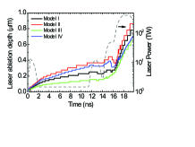
We consider a typical ignition laser pulse shape used in CH Rev5 design for the National Ignition Facility Haan , which is presented in Fig. 1. The peak laser intensity is taken as W/cm2. As shown, the pre-pulse finishes at around 16 ns where it is 49 TW, and then the main-pulse begins. Therefore, our - pulse for this work is laser before 16 ns and laser thereafter. The four models we consider in simulations are given in the table. In model I, II and III, it is a solid Au plane target driven by 2, 3 and 4 lasers, respectively. In model IV, it is a foam-solid Au plane target driven by the 4-2 laser. The solid target has a thickness of 40 m with = 19.24 g/cm3. The ”foam-solid” target is composed by two parts: a foam part with = 0.05 g/cm3 and = 40 m and a solid part with = 19.24 g/cm3 and = 39 m, with the foam part facing to the laser source. The areal density of the foam part equals to a solid layer with 19.24 g/cm3 in density and 1 m in thickness. The reason for taking such a thickness for the foam part is because the laser ablation depth is approximately 1 m for Au driven by the CH Rev5 ignition laser pulse. We use such a thin foam layer only for the laser deposition region just to investigation whether the foam can help to increase the laser to x-ray conversion efficiency under the - pulse as compared to the solid Au under the pulse. Moreover, we take = 39 m for the solid part of the foam-solid Au while = 40 m for the solid Au, just to keep the same areal density for both targets, as mentioned in Sec. I.
III SIMULATIONS and DISCUSSIONS
In in-direct drive approach, the laser absorption efficiency, the laser to x-ray conversion efficiency, the x-ray output and its spectrum are very important for hohlraum energetics and capsule implosion performances, while they are strongly connected to both laser and target parameters. In this section, we present and compare the simulation results from RDMG for the four models .
The laser ablation depth is decided not only by laser intensity and laser wavelength, but also by the initial density of target MTV . Presented in Fig. 1 is for all models. Here, we use 19.24 g/cm3 as the nominated density of the foam part and calculate under this nominated density for model IV. The results are discussed below. (1) For the same target, strongly depends on , and it is smaller at a longer . For the first three models, is about 0.7 m at 2, 0.78 m at 3 and 0.86 m at 4 at the end of the laser pulse. (2) is more sensitive to during pre-pulse than main-pulse. Fitting from the first three models, we have for pre-pulse and for the main-pulse. (3) During the main-pulse, is mainly decided by while relatively insensitive to . Models III and IV have almost the same because they both use 2 during the main-pulse.
For the laser absorption efficiency given in this paper, we only consider the laser absorption via inverse bremsstrahlung. The laser backscatter caused by LPI is not taken into considerations in this work, because present simulation results, including results from 2D codes, cannot adequately describe the observed LPI Kline056314 and therefore a qualitatively study on backscatter requires the experimental measurements. From our simulations, is higher at a shorter , and it is higher inside the foam-solid Au than inside the solid Au under the same laser pulse with same . Nevertheless, rises sharply as time, reaching in less than 1 ns and approaching in all models. Therefore, has few difference among the four models.
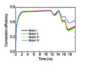
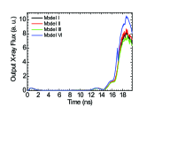
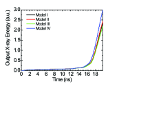
Presented in Fig. 2 is the temporal evolutions of for all models. The results are discussed below. (1) rises rapidly during the first step of the ignition laser pulse and reaches around at about 2ns for all models. (2) drops at the frontiers of all later steps when the laser power rises steeply. (3) is lower at a longer , but it can be remarkably increased by the foam layer of the foam-solid Au. From the results of the first three models which use solid Au, is at 4, at 3 and at 2 at the end of the laser pulse. However, the foam layer of the foam-solid Au can remarkably increase at 2, and can make even obviously higher than 4 with solid Au. In model IV, is about at the end of laser pulse, which is higher than the 2 model, higher than the 3 model, and higher than the 4 model with solid Au. As a result of the increased in the foam-solid Au, both output x-ray flux and x-ray energy driven by 2 laser are be remarkably increased in model IV, and they can be even higher than the cases driven by 3 and 4 with solid Au. From Fig. 3 and Fig. 4, the output x-ray flux and x-ray energy of model IV is about higher than the 2 model, higher than the 3 model, and higher than the 4 model which all use solid Au.
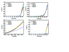
In order to understand why the x-ray output can be increased with a foam layer, we compare all kinds of energies of the laser ablation region among the four models, where the electronic density is lower than the critical density and the laser can be deposited. Recall that in model IV, the foam layer faces to the laser source and has a thickness equal to the laser ablation depth. Hence, the main influences caused by the foam layer mainly happen in the laser ablation region. Presented in Fig.5 is temporal evolutions of the electronic thermal energy , the ionic potential energy , the plasma kinetic energy , and the radiation energy for all models. Here, we take an arbitrary unit for these energies. As shown, all , , and depend on both and , but with very different behaviors. Notice that we have neglected the ionic thermal energy in Fig.5 because it is very small in the laser ablation region and can be neglected as compared to all other kinds of energies.
According to our simulation results, both and are higher at a longer , and they are higher in the foam-solid Au than in the solid Au. From Fig.5, is 0.92, 0.79 and 0.65 in the solid Au driven by the laser pulses at 2, 3 and 4, respectively; and it is 1.04 in the foam-solid Au under the 4-2 pulse. Again from Fig.5, is about 0.11, 0.11 and 0.08 in the solid Au driven by the laser pulses at 2, 3 and 4, respectively; and it is 0.12 in the foam-solid Au under the 4-2 pulse. However, the differences of and among these four models are not remarkable. Nevertheless, these results are connected to the electron thermal conduction model used in our simulations, and it is worth to be checked by future simulations with more accurate physics models.
In contrast, both and are remarkably decreased by using the foam-solid Au as compared to the solid Au. Here, we only compare model IV with model I which uses solid Au driven by 3 laser, because the differences among the first three models are small. From Fig.5, of model IV is 43 lower than model I, and of model IV is about 92 lower than model I. It means that in the laser ablation region, the kinetic energy of model IV is down by about half from model I, and the radiation energy of model IV decreases by an order of magnitude over model I. In the following, we discuss the reasons for such remarkable decreases of and , respectively.
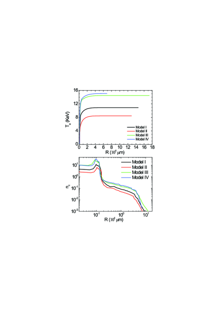
There are two reasons for the decrease of in the foam-solid Au. One reason is due to a thinner in the foam than in the solid, as shown in Fig.1. Another one is due to the propagation competition between the radiation front and sonic speed. According to Refs.HR2005 and HR2008 , the radiation front propagates subsonically and part of the absorbed energy is wasted by the flow kinetic energy for the solid target, while the front velocity is supersonic and can devote almost all of the absorbed energy to heating the material for the foam target. Presented in Fig.6 is the spatial distributions of electron temperature and normalized electron density at 19.5 ns before the laser pulse ends. As presented, model IV with foam-solid Au has a much shorter expansion than the solid target models. In addition, is higher at a longer ; and in model IV is close to model III, because they both use laser during the main-pulse. Moreover, the spacial distributions of are sensitive to , and is obviously lower at a shorter . This is the reason why LPI levels are lower at 3 and 4. As it is shown, of model IV is close to that of model III at 0.02, again because they both use laser during the main-pulse. Notice that a lower LPI backscatters of model IV can be expected than model III, because they have a similar spacial distribution of while model IV has a higher than model III. Nevertheless, as we have mentioned above, the LPI levels needs to be measured by experiments for the quantitatively study.
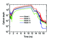
The reason for the decrease of inside the foam-solid Au has not been discussed in previous publications, but it is not surprising. Presented in Fig.7 is the temporal evolutions of the optical depth for all models. As shown, optical depth of the foam-solid is remarkably decreased about 4 to 7 times as compared to the solid models, and this is due to its shorter expansion and higher than the solid models.
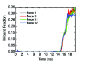
Finally, it is worth to compare the M-band fraction between the foam-solid target and the solid target, because the x-ray spectrum is very important for the implosion performancesOlson . The portion of the X-ray flux above 1.8 keV generated in the laser-heated Au can preheat capsule and arouse hydrodynamic instabilities lindl2003 ; Huo2012 . In our simulations, we define the emissions between 1.8 keV and 4 keV as the M-band of Au. Presented in Fig. 8 is temporal evolutions of for all models. As shown, is very small before 14 ns, but later it increases rapidly with laser power and reaches about at around 16 ns for all models. For the first three models with the solid Au, varies as while the differences are small. However, is more sensitive to . For model IV which uses the foam-solid target, obviously decreases as compared to the results of the solid Au. At around 19 ns, is around in the first three models, while it is around in models IV. Therefore, can be clearly decreased with the foam-solid target.
In this work, we also simulate a model in which the foam-solid Au is driven by a 2 laser during whole ignition pulse and compare its simulation results with model IV. The comparisons show that their results are close, which is reasonable because they all use 2 for the main-pulse. In addition, we also consider the foam-solid targets with = 0.25 g/cm3 and = 80 m or = 1 g/cm3 and = 20 m for the foam part, and their simulation results have no big differences from what we have for model IV. In fact, to search the optimum of foam for ignition hohlraum design, one should study and compare the x-ray radiations inside the hohlraums with various foam density under an ignition laser drive by using 2D or 3D simulations and performing systematic experiments with both modest energy (SGIII and Omega) and MJ scale lasers such as the NIF and LMJ. In future studies, a thick foam should be used, which thickness can cover both laser ablated region and radiation ablated region.
IV SUMMARY
We have proposed to drive a foam hohlraum wall with an ignition laser pulse by the 4-2 ignition pulse, in order to take the advantage of 4 laser in its low LPI during the pre-pulse, the advantage of 2 laser in its relatively high energy output and low damage threshold during the main-pulse, and the advantage of foam in its high , high and relatively low M-band fraction in its radiation spectrum. The advantage of foam in a higher was predicted and demonstrated in previous publications. In this work, we have demonstrated the advantage of foam in a higher by comparing the laser ablations between a solid target and a foam-solid target under an ignition laser pulse with our 1D simulations. As a result, can be increased by in the foam-solid Au under the 4-2 pulse as compared to a pure solid Au under a 3 laser. Our studies have shown that the increase of of the foam-solid Au is due to the decreases of its kinetic energy and radiation energy as compared to a solid Au, and the decrease of the radiation energy is caused by the shorter optical depth inside a foam. In addition, a lower LPI levels is expected from foam than from solid because of its higher electronic temperature in the laser deposited region.
Because 2 laser energy delivered to drive a fusion target can exceed 3 by a factor of about 1.1 to 1.2, together with the increased , and the decreased LPI levels inside the foams, it may provide a larger and flexible design space for ignition with a foam hohlraum wall and a 4-2 laser pulse. Because of the low damage threshold of the 2 laser at high power laser, we can therefore expect a remarkable increase of shot number at high laser energy power on a laser ignition facility for ignition study. Nevertheless, it is mandatory to have experiments for an understanding and demonstration of acceptable LPI levels and target coupling physics of 2 lasers.
Acknowledgements.
The authors wish to acknowledge the beneficial help from Guoli Ren, Yaohua Chen, Yongsheng Li, and Wanguo Zheng. This work is supported by the Development Foundation of CAEP (Grant No. 2013A0102002) and the National Natural Science Foundation of China (Grant No. 11475033).References
- (1) J. D. Lindl, B. A. Hammel, and B. G. Logan, D. D. Meyerhofer, S. A. Payne and J. D. Sethian, Plasma Phys. Control. Fusion 45, A217-A234 (2003).
- (2) J. D. Lindl, O. Landen, J. Edwards, E. Moses, and NIC Team, “Review of the National Ignition Campaign 2009-2012”, Phys. Plasmas 21, 020501 (2014).
- (3) W. Zheng, X. Wei, Q. Zhu, F. Jing, D. Hu, J. Su, K. Zheng, X. Yuan, H. Zhou, W. Dai, W. Zhou, F. Wang, D. Xu, X. Xie, B. Feng, Z. Peng, L. Guo, Y. Chen, X. Zhang, L. Liu, D. Lin, Z. Dang, Y. Xiang, and X. Deng, High Power Laser Science and Engineering 4, doi:10.1017/hpl.2016.20 (2016).
- (4) K. Lan, J. Liu, Z. Li, X. Xie, W. Huo, Y. Chen, G. Ren, C. Zheng, D. Yang, S. Li, Z. Yang, L. Guo, S. Li, M. Zhang, X. Han, C. Zhai, L. Hou, Y. Li, K. Deng, Z. Yuan, X. Zhan, F. Wang, G. Yuan, H. Zhang, B. Jiang, L. Huang, W. Zhang, K. Du, R. Zhao, P. Li, W. Wang, J. Su, X. Deng, D. Hu, W. Z, H. Jia, Y. Ding, W. Zheng, X. He, Matter and Radiation at Extremes 1, 8 (2016).
- (5) E. M. Campbell, R. Cauble, and B. A. Remington, AIP Conference Proceedings 429, 3 (1998).
- (6) J. Giorla, J. Bastian, C. Bayer, B. Canaud, M. Casanova, F. Chaland, C. Cherfils, C. Clique, E. Dattolo, P. Fremerye, D. Galmiche, F. Garaude, P. Gauthier, S. Laffite, N. Lecler, S. Liberatore, P. Loiseau, G. Malinie, L. Masse, A. Masson, M. C. Monteil, F. Poggi, R. Quach, F. Renaud, Y. Saillard, P. Seytor, M. Vandenboomgaerde, J. Van der Vliet, and F. Wagon,Plasma Phys. Control. Fusion 48 B75 (2006).
- (7) P. Neumayer, R. L. Berger, D. Callahan, L. Divol, D. H. Froula, R. A. London, B. J. MacGowan, N. B. Meezan, P. A. Michel, J. S. Ross, C. Sorce, K. Widmann, L. J. Suter, and S. H. Glenzer, Phys. Plasmas 15, 056307 (2008).
- (8) J. L. Kline, S. H. Glenzer, R. E. Olson, L. J. Suter, K. Widmann, D. A. Callahan, S. N. Dixit, C. A. Thomas, D. E. Hinkel, E. A. Williams, A. S. Moore, J. Celeste, E. Dewald, W. W. Hsing, A. Warrick, J. Atherton, S. Azevedo, R. Beeler, R. Berger, A. Conder, L. Divol, C. A. Haynam, D. H. Kalantar, R. Kauffman, G. A. Kyrala, J. Kilkenny, J. Liebman, S. Le Pape, D. Larson, N. B. Meezan, P. Michel, J. Moody, M. D. Rosen, M. B. Schneider, B. Van Wonterghem, R. J. Wallace, B. K. Young, O. L. Landen, and B. J. MacGowan, Phys. Rev. Lett. 106, 085003 (2011).
- (9) D. H. Froula, L. Divol, N. B. Meezan, S. Dixit, J. D. Moody, P. Neumayer, B. B. Pollock, J. S. Ross, and S. H. Glenzer, Phys. Rev. Lett. 98, 085001 (2007).
- (10) C. A. Haynam, P. J. Wegner, J. M. Auerbach, M. W. Bowers, S. N. Dixit, G. V. Erbert, G. M. Heestand, M. A. Henesian, M. R. Hermann, K. S. Jancaitis, K. R. Manes, C. D. Marshall, N. C. Mehta, J. Menapace, E. Moses, J. R. Murray, M. C. Nostrand, C. D. Orth, R. Patterson, R. A. Sacks, M. J. Shaw, M. Spaeth, S. B. Sutton, W. H. Williams, C. C. Widmayer, R. K. White, S. T. Yang, and B. M. Van Wonterghem, Appl. Opt. 46, 3276 (2007).
- (11) L. J. Suter, S. Glenzer, S. Haan, B. Hammel, K. Manes, N. Meezan, J. Moody, M. Spaeth, and L. Divol K. Oades and M. Stevenson, Phys. Plasmas 11, 2738 (2004).
- (12) C. Niemann, R. L. Berger, L. Divol, D. H. Froula, O. Jones, R. K. Kirkwood, N. Meezan, J. D. Moody, J. Ross, C. Sorce, L. J. Suter, and S. H. Glenzer, Phys. Rev. Lett. 100, 045002 (2008).
- (13) S. Depierreux, D. T. Michel, V. Tassin, P. Loiseau, C. Stenz, and C. Labaune, Phys. Rev. Lett. 103, 115001 (2009).
- (14) R. M. Stevenson, K. Oades, B. R. Thomas, M. Schneider, G. E. Slark, L. J. Suter, R. Kauffman, D. Hinkel, and M. C. Miller, Phys. Rev. Lett. 94, 055006 (2005).
- (15) C. Labaune, Nature Phys. 3, 680 (2007).
- (16) S. Depierreux, P. Loiseau, D. T. Michel, V. Tassin, C. Stenz, P.-E. Masson-Laborde, C. Goyon, V. Yahia, and C. Labaune, Phys. Plasmas 19, 012705 (2012).
- (17) Z. Li, J. Zheng, X. Jiang, Z. Wang, D. Yang, H. Zhang, S. Li, Q. Yin, F. Zhu, P. Shao, X. Peng, F. Wang, L. Guo, P. Yuan, Z. Yuan, L. Chen, S. Liu, S. Jiang, and Y. Ding, Phys. Plasmas 19, 062703 (2012).
- (18) M. D. Rosen and J. H. Hammer, Phys. Rev. E. 72, 056403 (2005).
- (19) P. E. Young, M. D. Rosen, J. H. Hammer, W. S. Hsing, S. G. Glendinning, R. E. Turner, R. Kirkwood, J. Schein, C. Sorce, J. H. Satcher, Jr., A. Hamza, R. A. Reibold, R. Hibbard, O. Landen, A. Reighard, S. McAlpin, M. Stevenson, and B. Thomas, Phys. Rev. Lett. 101, 035001 (2008).
- (20) Y. Dong, W. Shang, J. Yang, L. Zhang, W. Zhang, Z. Li, L. Guo, X. Zhan, H. Du, B. Deng, and Y. Pu, Phys. Plasmas 20, 123305 (2013).
- (21) L. Zhang, Y. Ding, S. Jiang, J. Yang, H. Li, L. Kuang, Z. Lin, L. Jing, L. Li, B. Deng, Z. Yuan, T. Chen, G. Yuan, X. Tan, and P.Li, Phys. Plasmas 22, 110703 (2015).
- (22) L. Zhang, Y. Ding, Z. Lin, H. Li, L. Jing, Z. Yuan, Z. Yang, X. Tan, L. Kuang, W. Zhang, L. Li, P. Li, G. Yuan, S. Jiang and B. Zhang, Nucl. Fusion 56, 036006 (2016).
- (23) L. Zhang, Y. Ding, J. Yang, S. Wu, and S. Jiang, Phys. Plasmas 18, 033301 (2011).
- (24) Y. Dong, L. Zhang, J. Yang, and W. Shang, Phys. Plasmas 20, 123102 (2013).
- (25) T. Feng, D. Lai, and Y. Xu, Chinese J. Comput. Phys. 16, 199-205 (1999).
- (26) Y. Xu, S. Jiang, D. Lai, W. Pei, Y. Ding, T. Chang, K. Lan, S. Li, and T, Feng, Laser and Particle Beams 24, 495(2006)
- (27) Y. Li, W. Y. Huo and K. Lan, Phys. Plasmas 18, 022701 (2011); W. Y. Huo, K. Lan, Y. Li, D. Yang, S. Li, X. Li, C. Wu, G. Ren, Y. Zhao, S. Zou, W. Zheng, P. Gu, M. Wang, R. Yi, X. Jiang, T. Song, Z. Li, L. Guo, Y. Liu, X. Zhan, F. Wang, X. Peng, H. Zhang, J. Yang, S. Liu, S. Jiang, and Y. Ding, Phys. Rev. Lett. 109, 145004(2012).
- (28) Y. Xu, S. Wu, and W. Zheng, Phys. Plasmas 22, 042708 (2015).
- (29) T. Feng, D. Lai, Y. Xu, and J. Li, Annual Reports of China Academy of Engineering Physics 1998 (Atomic Energy Press, Chengdu, 1998), p. 286 (in Chinese).
- (30) R. S. Cohen, L. Spitzer, and P. M. Routly, Phys. Rev. 80, 230 (1950).
- (31) L. Spitzer and R. Hrm, Phys. Rev. 89, 977 (1953).
- (32) R. C. Malone, R. L. McCrory, and R. L. Morse, Phys. Rev. Lett. 12, 721 (1975).
- (33) S. W. Haan, J. D. Lindl, D. A. Callanhan, D. S. Clark, J. D. Salmonson, B. A. Hammel, L. J. Atherton, R. C. Cook, M. J. Edwards, S. Glenzer, A. V. Hamza, S. P. Hatchett, M. C. Herrmann, D. E. Hinkel, D. D. Ho, H. Huang, O. S. Jones, J. Kline, G. Kyrala, O. L. Landen, B. J. MacGowan, M. M. Marinak, D. D. Meyerhofer, J. L. Milovich, K. A. Moreno, E. I. Moses, D. H. Munro, A. Nikroo, R. E. Olson, K. Peterson, S. M. Pollaine, J. E. Ralph, H. F. Robey, B. K. Spears, P. T. Springer, L. J. Suter, C. A. Thomas, R. P. Town, R. Vesey, S. V. Weber, H. L. Wilkens, and D. C. Wilson, Phys. Plasmas 18, 051001 (2011).
- (34) S. Atzeni, J. Meyer-ter-Vehn, The Physics of Inertial Fusion (Oxford Science, Oxford, 2004).
- (35) J. L. Kline, D. A. Callahan, S. H. Glenzer, N. B. Meezan, J. D. Moody, D. E. Hinkel, O. S. Jones, A. J. MacKinnon, R. Bennedetti, R. L. Berger, D. Bradley, E. L. Dewald, I. Bass, C. Bennett, M. Bowers, G. Brunton, J. Bude, S. Burkhart, A. Condor, J. M. Di Nicola, P. Di Nicola, S. N. Dixit, T. D oeppner, E. G. Dzenitis, G. Erber, J. Folta, G. Grim, S. Lenn, A. Hamza, S. W. Hann, J. Heebner, M. Henesian, M. Hermann, D. G. Hicks, W. W. Hsing, N. Izumi, K. Jancaitis, O. S. Jones, D. Kalantar, S. F. Khan, R. Kirkwook, G. A. Kyrala, K. LaFortune, O. L. Landen, L. Lain, D. Larson, S. Le Pape, T. Ma, A. G. MacPhee, P. A. Michel, P. Miller, M. Montincelli, A. S. Moore, A. Nikroo, M. Nostrand, R. E. Olson, A. Pak, H. S. Park, M. B. Schneider, M. Shaw, V. A. Smalyuk, D. J. Strozzi, T. Suratwala, L. J. Suter, R. Tommasini, R. P. J. Town, B. Van Wonterghem, P. Wegner, K. Widmann, C. Widmayer, H. Phys. Plasmas 20, 056314 (2013).
- (36) R. E. Olson, R. J. Leeper, A. Nobile, and J. A. Oerte, Phys. Rev.Lett. 91, 235002 (2003).