Asymmetric isolated skyrmions in polar magnets with easy-plane anisotropy
Abstract
We introduce a new class of isolated magnetic skyrmions emerging within tilted ferromagnetic phases of polar magnets with easy-plane anisotropy. The asymmetric magnetic structure of these skyrmions is associated with an intricate pattern of the energy density, which exhibits positive and negative asymptotics with respect to the surrounding state with a ferromagnetic moment tilted away from the polar axis. Correspondingly, the skyrmion-skyrmion interaction has an anisotropic character and can be either attractive or repulsive depending on the relative orientation of the skyrmion pair. We investigate the stability of these novel asymmetric skyrmions against the elliptical cone state and follow their transformation into axisymmetric skyrmions, when the tilted ferromagnetic moment of the host phase is reduced. Our theory gives clear directions for experimental studies of isolated asymmetric skyrmions and their clusters embedded in tilted ferromagnetic phases.
pacs:
75.30.Kz, 12.39.Dc, 75.70.-i.Magnetic chiral skyrmions are particle-like topological solitons with complex spin structure Bogdanov94 ; Bogdanov89 ; review ; Nagaosa13 which are the solutions of the field equations of the Dzyaloshinskii’s theory Dz64 . Recently, skyrmion lattice states and isolated skyrmions were discovered in bulk crystals of chiral magnets near the magnetic ordering temperatures Muehlbauer09 ; Wilhelm11 ; Kezsmarki15 and in nanostructures with confined geometries over larger temperature regionsYu10 ; Yu11 ; Du15 ; Liang15 . The small size, topological protection and easy manipulation of skyrmions by electric fields and currents Schulz12 ; Jonietz10 ; Hsu17 generated enormous interest in their applications in information storage and processing Sampaio13 ; Tomasello14 . Depending on the crystal symmetry of the host materials, distinct classes of skyrmions, such as Bloch and Néel skyrmions, or anti-skyrmions Nayak17 can be realized. In particular, Néel skyrmions were recently found in GaV4S8 and GaV4Se8, which are magnetic semiconductors with non-chiral but polar crystal structure Kezsmarki15 ; Bordacs17 . Néel skyrmions emerging in such multiferroic hosts are associated with an electric polarization pattern, which can be exploited for their electric field control Ruff15 .
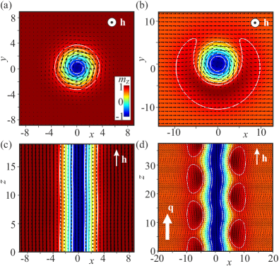
The current interest of skyrmionics is focused on isolated axisymmetric skyrmions within the polarized ferromagnetic (PFM) state of non-centrosymmetric magnets. All the spins around such skyrmions are parallel to the applied magnetic field and point opposite to the spin in the center of the skyrmion, as visualized in Figs. 1 (a) & (c). The internal structure of such axisymmetric skyrmions, generally characterized by repulsive skyrmion-skyrmion interaction, has been thoroughly investigated theoretically Bogdanov94b ; LeonovNJP16 and experimentally by spin-polarized scanning tunneling microscopy in PdFe bilayers with surface induced Dzyaloshinskii-Moriya interactions (DMI) and strong easy-axis anisotropy Romming13 ; Romming15 . The existence region of axisymmetric skyrmions was found to be restricted by strip-out instabilities at low fields and a collapse at high fields LeonovNJP16 .
The internal spin pattern of isolated skyrmions can break the rotational symmetry once placed into the conical phase of bulk helimagnets LeonovJPCM16 , such as the cubic B20 compounds. These skyrmions are not uniform along their axes. Though their central core region nearly preserves the axial symmetry, the domain-wall region, which connects the core with the embedding conical state, is asymmetric LeonovJPCM16 . This asymmetric profile of the cross-section forms a screw-like modulation along the skyrmion core, as depicted in Figs. 1 (b) & (d). These asymmetric isolated skyrmions, which can exhibit an attractive skyrmion-skyrmion interaction, were proposed to underlie the precursor phenomena near the ordering temperatures in chiral B20 magnets (MnSi, FeGe) LeonovJPCM16 and have prospects in spintronics as an alternative to the common axisymmetric skyrmionsLeonovAPL16 .
In this Letter we introduce a new type of isolated skyrmions within the tilted ferromagnetic (TFM) state of magnets with polar crystal structure and easy-plane anisotropy. Such skyrmions are forced to develop an asymmetric shape in order to match their spin pattern with that of the TFM state, meanwhile preserving their topological charge . We find that—unlike the repulsive axisymmetric skyrmions and the attractive asymmetric skyrmions respectively embedded in the PFM state and the conical phase of chiral magnets—the asymmetric skyrmions emerging in the TFM state of polar magnets exhibit anisotropic inter-skyrmion potential. Depending on the relative orientation of the two individual skyrmions, this potential can be attractive, leading to the formation of biskyrmion or multiskyrmion states, or repulsive.
Chiral solitons and modulated phases can be derived by minimizing the energy functional of a non-centrosymmetric ferromagnet Dz64 ; Bak80 ; thesis :
| (1) |
Here, we use reduced values of the spatial variable, with being the periodicity of the modulated states. is the exchange stiffness constant. The sign of the Dzyaloshinskii constant determines the sense of rotation. is the uniaxial anisotropy of easy-plane type, is the unity vector along the magnetization, and is the applied magnetic field in reduced units.
Depending on the crystal symmetry, the DMI energy includes certain combinations of Lifshitz invariants Dz64 ; Bogdanov89 . Particularly, for cubic helimagnets, such as MnSi Muehlbauer09 , FeGe Yu11 , Cu2OSeO3 Seki12 and -type Mn alloys Tokunaga15 , belonging to the chiral (T) and 432 (O) crystallographic classes, the DMI is reduced to the following form
| (2) |
and stabilizes Bloch-type modulations. Two types of isolated skyrmions have been found to exist for DMI (2): axisymmetric skyrmions within the PFM state and asymmetric skyrmions within the conical phase, respectively visualized in Fig. 1 (a) & (b).
In the phase diagram of noncentrosymmetric ferromagnets with DMI (2) and easy-plane uniaxial anisotropy, the conical phase is the only stable modulated state Wilson2014 ; Butenko10 ; Rowland2016 . Other states including skyrmion lattices and spirals are only metastable solutions of the model, though can be stabilized in real materials by several means, such as thermal fluctuations and confined geometry. Axisymmetric isolated skyrmions exist as metastable excitations of the PFM state for , while asymetric skyrmions are present for Wilson2014 .
The form of DMI is different for materials belonging to polar uniaxial (Cnv) crystallographic classes,
| (3) |
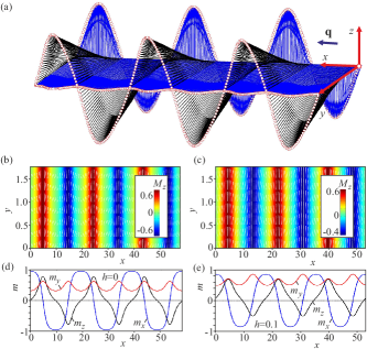
which are the subject of the present work. This type of DMI can stabilize skyrmions and spirals (cycloids) of Néel-type with the rotation plane of the magnetization including the wave vector and the polar axis (Fig. 2). As the conical phase is suppressed in this case, the phase diagram reveals wide regions of different states with one- and two-dimensional modulations, as discerned in Figs. 1 and 4 of the Supplement Rowland2016 ; Tretiakov2016 ; Banerjee2014 . The TFM and PFM states in polar magnets with easy-plane anisotropy host two distinct types of isolated skyrmions, as shown in Fig. 2.
Isolated axisymmetric Néel skyrmions within the PFM phase are characterized by azimuthal () and polar () angles of the spins according to
| (4) |
Here the boundary conditions are , , while and are cylindrical coordinates of the spatial variable.
On the other hand, the isolated Néel skyrmions embedded in the TFM phase are confined by the following in-plane boundary conditions:
| (5) |
These boundary conditions violate the rotational symmetry, forcing the skyrmions to develop an asymmetric shape.
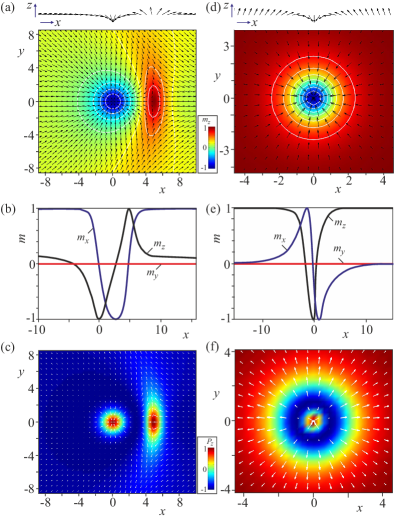
The results of the numerical minimization of the energy functional (1) with boundary conditions (5) are shown in Figs. 2 (a) & (b). When the canted moment of the TFM state is along the axis, the asymmetry is clearly reflected in both and . As implied by , such skyrmions consist of a strongly localized nearly axisymmetric core and an asymmetric transitional region toward TFM state. From the left side of the depicted skyrmion, the magnetization rotates directly from to in the skyrmion center. In contrast, at the right side, the magnetization first passes through () and then converges back to . This is the reason of the crescent-shaped anti-skyrmion-like region with a positive energy density over the TFM state, shown in Figs. 3 (b) & (c), which is necessary to maintain the topological charge of such a highly distorted asymmetric skyrmion.
As already mentioned, Néel skyrmions in insulating hosts can have a polar dressing in addition to their magnetic pattern. The asymmetry of Néel skyrmions embedded in the TFM phase is also reflected in the spatial pattern of their electric polarization, as visualized in Fig. 2 (c) in comparison with the polar pattern of an axisymmetric Néel skyrmion in Fig. 2 (f). The magnetically induced polarization was calculated using the lowest-order magnetoelectric terms allowed in materials with C4v or C6v symmetry:
| (6) |
For the polarization patterns shown in Figs. 2 (c) and (f), we set ==- and used the normalization condition, =1. While the feasibility of electric-field-driven switching has been demonstrated already for Néel skyrmions Hsu17 , the asymmetry of the polarization pattern, characteristic to the isolated skyrmions studied here, can be exploited to control their orientation by in-plane electric fields.
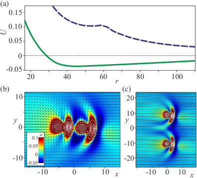
Asymmetric skyrmions within the TFM phase can be considered as cross-sections of asymmetric skyrmions in the conical phases, shown in Figs. 1 (b) & (d) LeonovJPCM16 ; LeonovAPL16 . However, the DMI term (3) stabilizing Néel skyrmions does not support any modulation along the axis. Thus, the asymmetry of Néel skyrmions created within the TFM state is uniform along the axis, which results in a non-trivial character of inter-skyrmion potential, displayed in Fig. 3 (a). Figs. 3 (b) & (c) present energy density distributions in skyrmion pairs for two mutual orientations, head-to-head and side-by-side. In the head-to-head configuration, skyrmions form pairs with a fixed inter-skyrmion distance, implying the attractive nature of their interaction, as clear from the green curve in Fig. 3 (a). Therefore, these skyrmions are expected to form 1D chains running along the canted magnetization component of the TFM phase Lin2015 . The calculated inter-skyrmion potential for the side-by-side configuration, the blue curve in Fig. 3 (a), reveals the repulsive character of skyrmion-skyrmion interaction at large distances with a local minimum (or saddle point) at smaller distances. Such a behavior of the inter-skyrmion potential is related to the positive and negative asymptotics of the energy density toward the TFM state. In general, we argue that the inter-skyrmion potential inherently contains a number of minima separated by saddle points (see also Supplement for additional details).
In contrast, the asymmetric pattern of Bloch skyrmions is tightly linked to the conical modulation of the host phase and rotates around the axis in the same way for each individual skyrmions. This synchronized screw-like rotation of the asymmetry for a pair of such skyrmions leads to an overall attractive potential, by averaging over head-to-head, side-by-side and intermediate configurations alternating along the axis LeonovJPCM16 .
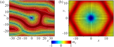
The asymmetric skyrmions within the TFM state can exist only for , i.e. require a relatively strong easy-plane anisotropy. For isolated skyrmions undergo an instability towards the elliptical cone state, as demonstrated in Fig. 5 (a) (see Ref. Rowland2016, and Supplement for a detailed information on the structure of the elliptical cone and its lability region). This instability resembles the elliptical instability of skyrmions into spirals considered in Ref. LeonovNJP16, and allows to generalize the considered phenomenon: isolated skyrmions tend to elongate into one-dimensional states (elliptical cones or spirals) which have smaller energy for given control parameters.
The TFM state turns into the PFM state with at the line . In the PFM state the rotational symmetry is recovered and isolated skyrmions become axisymmetric with and , as shown in Figs. 2 (d) & (e). The core region and the surrounding ring have positive and negative energy densities, respectively, implying a repulsive skyrmion-skyrmion interaction Bogdanov94 .
Néel skyrmions can also form the thermodynamically stable skyrmion lattices. Skyrmions within unit cells of such lattices have perfectly hexagonal shape, as seen in Fig. 5 (b), and do not bear any hint on the asymmetric skyrmion structure or skyrmion instability into the elliptical cone.
Results obtained within the model (1) with DMI (3) are valid for bulk polar magnets with axial symmetry as well as for thin films with interface induced DMI. In particular, bulk polar magnetic semiconductors GaV4S8 Kezsmarki15 and GaV4Se8 Bordacs17 with the symmetry possess uniaxial anisotropy of easy-axis and easy-plane type, respectively. Since the magnitude of the effective anisotropy in these lacunar spinels strongly varies with temperature, these material family provides an ideal arena for the comprehensive study of anisotropic effects on modulated magnetic states Bordacs17 . Skyrmions were also studied experimentally in various systems with interface induced DMI Romming13 ; Romming15 ; Dupe16 ; Woo16 . In these thin film structures, the rotational symmetry can also be broken by different anisotropic environments due to lattice strains or reconstructions in the magnetic surface layers Hagemeister16 , as has been discussed recently for the double atomic layers of Fe on Ir(111) Hsu16 . These structural anisotropies also promote the formation of asymmetric skyrmions.
In conclusion, we found a new type of isolated skyrmions emerging in tilted FM states of polar magnets with easy-plane anisotropy. These novel solitonic states are characterized by an asymmetric shape and an anisotropic inter-skyrmion potential. Our results are of particular interest for 2D materials like thin films, surfaces, interfaces, where easy-plane anisotropy can coexist with Rashba-type spin-orbit coupling, activated by the broken surface-inversion symmetry Rowland2016 ; Banerjee2014 . In order to fully explore their characteristics and functionalities, the internal structure of these asymmetric skyrmions should be studied experimentally, as was done for the axisymmetric individual skyrmions within polarized FM states Romming13 ; Romming15 .
The authors are grateful to K. Inoue, A. Bogdanov, and Y. Togawa for useful discussions. This work was funded by JSPS Core-to-Core Program, Advanced Research Networks (Japan). This work was supported by the Hungarian Research Fund OTKA K 108918.
I Supplementary Information
I.1 Elliptical cone
We analyze solutions of the model (1) starting from one-dimensional cycloids and elliptical cones (Fig. 5). We direct their -vectors along , and thus get the polar and azimuthal angles as functions of only one spatial coordinate: . The twisting DMI acquires the following form:
| (7) |
For a cycloid, and thus (the notation is used). For the average value of DMI energy equals like in undistorted spirals with uniform rotation (Fig. 7 (b)). In the applied magnetic field, the rotational part of the cycloids is squeezed to narrow domain walls between wide domains polarized along the field. Thus, the rotational energy gradually decreases to 0. Usually, such a cycloid is considered to satisfy the boundary conditions: where is a pitch of a cycloid subject to minimization. Thus, in the case of the easy-plane uniaxial anisotropy as well as in the case of easy-axis anisotropy Butenko10 , the cycloid is believed to infinitely expand its period and transform into the TFM state at the line (Fig. 5; see also Fig. 12 in Ref. Wilson2014, ).
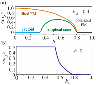
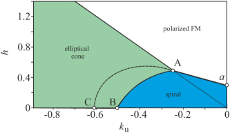
In our simulations, however, we show that the cycloidal spiral rather gives rise to the elliptical cone (Fig. 6) at the line (Fig. 5). An elliptical cone (EC) was introduced in Ref. Rowland2016, . Spins in this phase trace out a cone with an elliptical cross-section (Fig. 6 (a) - (e)). The angle of this cone is defined by the corresponding angle of the tilted FM state, . Such an EC develops from a cycloidal state by the second-order phase transition and gradually increases its -component (Fig. 7 (a)). At the line , EC continuously transforms into the polarized FM state (Fig. 5). For the EC transforms into the tilted FM state. We note that the TFM state is isotropic in plane. On the contrary, the EC develops its in-plane component perpendicular to the -vector. By this, the uni-directional sense of the magnetization rotation in EC is preserved, and the DMI energy of EC (7) is modified by the additional -dependence. At the lines and the rotational energy (7) falls to (Fig. 7 (b)).
I.2 The phase diagram of states
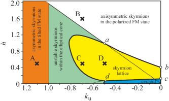
The complete phase diagram (Fig. 8) of states of the model (1) has been reproduced from Ref. Rowland2016, and includes stability regions of modulated phases and regions of metastable skyrmions. Points A-D indicate parameters for different solutions used in the manuscript: point A – asymmetric skyrmions within TFM phase (Fig. 2 (a) - (c)); point B – axisymmetric skyrmions within PFM phase (Fig. 2 (d) - (f)); point C - hexagonal skyrmion lattice (Fig. 4 (b)), point D - instability of asymmetric skyrmions with respect to the elliptical cone (Fig. 4 (a)).
The phase diagrams also allows to generalize the processes of skyrmion lattice formation. Along the line the skyrmion lattice appears as a result of condensation of isolated skyrmions (building blocks of the hexagonal skyrmion lattice), as found for axisymmetric skyrmions in the easy-axis case Bogdanov94 ; Butenko10 ; LeonovNJP16 . Along the line , hexagonal skyrmion lattice may appear as a result of local cutting of the cycloid (in this sense, two merons may be considered as nuclei of the skyrmion lattice Ezawa11 ). Along the first-order phase transition line , however, none of the aforementioned mechanisms is appropriate. Presumably, domains of the skyrmion lattice and the elliptical cone state coexist with non-trivial domain boundary between them.
I.3 Inter-skyrmion potential
To calculate the skyrmion-skyrmion interaction potential, the following procedure was proved to be appropriate for axisymmetric skyrmions LeonovNC15 and asymmetric skyrmions within the conical phase LeonovJPCM16 : the energy density (1) is minimized with the constraint imposed at the centers of two skyrmions as a function of the distance between skyrmion centers. This procedure, however, faces the following difficulty when applied to asymmetric skyrmions within TFM states: skyrmions will locally deform the surrounding TFM state to achieve the minimum of the system. Thus, only positions of (local and global) minima can be found precisely. To reconstruct the interaction potential with all underlying details, one should impose a control over the in-plane component of the TFM state, i.e. violate its in-plane isotropy.
References
- (1) A. Bogdanov and A. Hubert, J. Magn. Magn. Mater. 138, 255 (1994); 195, 182 (1999).
- (2) A. N. Bogdanov and D. A. Yablonskii, Zh. Eksp. Teor. Fiz. 95, 178 (1989) [Sov. Phys. JETP 68, 101 (1989)].
- (3) N. Nagaosa and Y. Tokura, Nat. Nanotechnol. 8, 899 911 (2013).
- (4) U. K. Rößler, A. A. Leonov, and A. N. Bogdanov, J. Phys. Conf. Ser. 303, 012105 (2011).
- (5) I. E. Dzyaloshinskii, Sov. Phys. JETP 19, 960 (1964).
- (6) S. Mühlbauer, et al., Science 323, 915 919 (2009).
- (7) H. Wilhelm, M. Baenitz, M. Schmidt, U. K. Roessler, A. A. Leonov, and A. N. Bogdanov, Phys. Rev. Lett. 107, 127203 (2011).
- (8) I. Kezsmarki et al., Nat. Mater. 14, 1116 1122 (2015).
- (9) X. Z. Yu, Y. Onose, N. Kanazawa, J. H. Park, J. H. Han, Y. Matsui, N. Nagaosa, and Y. Tokura, Nature (London) 465, 901 (2010).
- (10) X. Z. Yu et al., Nat. Mater. 10, 106 109 (2011).
- (11) H. Du et al., Nat. Commun. 6, 7637 (2015).
- (12) D. Liang, J. P. DeGrave, M. J. Stolt, Y. Tokura, and S.Jin, Nat. Commun. 6, 8217 (2015).
- (13) T. Schulz et al., Nat. Phys. 8, 301 304 (2012).
- (14) F. Jonietz, S. Mühlbauer, C. Pfleiderer, A. Neubauer, W. M nzer, A. Bauer, T. Adams, R. Georgii, P. Böni, R. A. Duine, K. Everschor, M. Garst, A. Rosch, Science 330, 1648 (2010).
- (15) P-J. Hsu et al., Nat. Nanotechnol. 12 123-126 (2017).
- (16) J. Sampaio, V. Cros, S. Rohart, A. Thiaville, and A. Fert, Nat. Nanotechnol. 8, 839844 (2013).
- (17) E. M. R. Tomasello, R. Zivieri, L. Torres, M. Carpentieri, and G. Finocchio, Sci. Rep. 4, 6784 (2014).
- (18) A. K. Nayak, V. Kumar, P. Werner, E. Pippel, R. Sahoo, F. Damay, U. K. Rößler, C. Felser, S. S. P. Parkin, arxiv. 1703.01017.
- (19) S. Bordacs et al., [arXiv: link available soon]
- (20) E. Ruff et al., Sci. Advances 1, e1500916 (2015).
- (21) A. Bogdanov, A. Hubert, phys. stat. sol. (b) 186, 527 (1994).
- (22) A. O. Leonov, T. L. Monchesky, N. Romming, A. Kubetzka, A. N. Bogdanov, and R. Wiesendanger, New J. of Phys. 18, 065003 (2016).
- (23) N. Romming, C. Hanneken, M. Menzel, J. E. Bickel, B. Wolter, K. von Bergmann, A. Kubetzka, and R. Wiesendanger, Science 341, 636 (2013).
- (24) N. Romming, A. Kubetzka, C. Hanneken, K. von Bergmann, and R. Wiesendanger, Phys. Rev. Lett. 114, 177203 (2015).
- (25) A. O. Leonov, T. L. Monchesky, J. C. Loudon, and A. N. Bogdanov, J. Phys.: Condens. Matter. 28, 35LT01 (2016).
- (26) A. O. Leonov, J. C. Loudon, A. N. Bogdanov, Appl. Phys. Lett. 109, 172404 (2016).
- (27) P. Bak and M. H. Jensen, J. Phys. C: Solid State Phys. 13, L881 (1980); O. Nakanishi, A. Yanase, A. Hasegawa, and M. Kataoka, Solid State Comm. 35, 995 (1980).
- (28) A. A. Leonov, Ph.D. thesis, Technical University Dresden (2012).
- (29) S. Seki, X. Z. Yu, S. Ishiwata, and Y. Tokura, Science 336, 198-201 (2012).
- (30) Y. Tokunaga et al., Nat. Commun. 6, 7638 (2015).
- (31) M. N. Wilson, A. B. Butenko, A. N. Bogdanov, and T. L. Monchesky, Phys. Rev. B 89 094411 (2014).
- (32) A. B. Butenko, A. A. Leonov, U. K. Rößler, and A. N. Bogdanov, Phys. Rev. B 82, 052403 (2010).
- (33) J. Rowland, S. Banerjee, M. Randeria, Phys. Rev. B 93, 020404 (2016).
- (34) U. Güngördü, R. Nepal, O. Tretiakov, K. Belashchenko, A. A. Kovalev, Phys. Rev. B 93, 064428 (2016).
- (35) S. Banerjee, J. Rowland, O. Erten, M. Randeria, Phys. Rev. X 4, 031045 (2014).
- (36) S.-Z. Lin, A. Saxena, C. Batista, Phys. Rev. B 91, 224407 (2015).
- (37) B. Dúpe, G. Bihlmayer, M. Böttcher, S. Blügel, and S. Heinze, Nat. Commun. 7, 11779 (2016).
- (38) S. Woo, K. Litzius, B. Krüger, M. Im, L. Caretta, K. Richter, M. Mann, A. Krone, R. Reeve, M. Weigand et al., Nat. Mater. 15, 501 (2016).
- (39) J. Hagemeister, E. Y. Vedmedenko, and R. Wiesendanger, Phys. Rev. B 94, 104434 (2016).
- (40) P. J. Hsu, A. Finco, L. Schmidt, A. Kubetzka, K. von Bergmann, and R. Wiesendanger, Phys. Rev. Lett. 116, 017201 (2016).
- (41) A. O. Leonov and M. Mostovoy, Nat. Commun. 6, 8275 (2015).
- (42) M. Ezawa, Phys. Rev. B 83, 100408 (2011).