Giant Ferrimagnetism and Polarization In A Mixed Metal Perovskite Metal-Organic Framework
Abstract
Perovskite metal-organic frameworks (MOFs) have recently emerged as potential candidates for multiferroicity. However, the compounds synthesized so far possess only weak ferromagnetism and low polarization. Additionally, the very low magnetic transition temperatures () also pose a challenge to the application of the materials.We have computationally designed a mixed metal perovskite MOF -\ce[C(NH2)3][(Cu0.5Mn0.5)(HCOO)3]- that is predicted to have magnetization two orders of magnitude larger than its parent (\ce[C(NH2)3][Cu(HCOO)3]), a significantly larger polarization (9.9 C/cm2), and an enhanced of up to 56 K, unprecedented in perovskite MOFs. A detailed study of the magnetic interactions revealed a novel mechanism leading to the large moments as well as the increase in the . Mixing a non-Jahn-Teller ion (Mn2+) into a Jahn-Teller host (Cu2+) leads to competing lattice distortions which are directly responsible for the enhanced polarization. The MOF is thermodynamically stable as evidenced by the computed enthalpy of formation, and can likely be synthesized. Our work represents a first step towards rational design of multiferroic perovskite MOFs through the largely unexlpored mixed metal approach.
Multiferroics are materials which possess ferromagnetic (FM), ferroelectric (FE) and structural order parameters within a single phase Cheong and Mostovoy (2007); Ramesh (2009); Picozzi and Ederer (2009); Tokura and Seki (2010); Brink and Khomskii (2008); Ma et al. (2011); Wang et al. (2009); Lee et al. (2010). These are highly promising not only for their use in multi-functional device applications but also for the interesting physics they reveal. Much of the research in the field has so far focussed on multiferroics based on inorganic transition metal oxides. In the last decade, there has been growing interest in metal-organic frameworks (MOFs) consisting of metal ions interconnected by organic linkers. The organic-inorganic duality in MOFs leads to many interesting physical properties Rosseinsky (2010); Xu et al. (2011) that can be exploited in applications such as gas storage and separation, catalysis, nonlinear optics, photoluminescence, magnetic and electric materials, and so on Stroppa et al. (2013); Ferrey (2008). The hybrid nature of these materials offers a vast chemical space for synthetic chemists to explore and, hence, also affords tunability of properties. MOFs with the perovskite ABX3 structure are of great interest, particularly those with multiferroic behavior arising due to hydrogen-bonds Stroppa et al. (2011); Jain et al. (2009). In the case of magnetic MOFs, for instance, one can control the nature of magnetic coupling through the variety of possible metal ions in the B-site, short ligands, co-ligands and radical ligands carrying spin degrees of freedom Demir et al. (2012). Recently, it has been shown that one can tune the magnitude of the ferroelectric polarization by carefully choosing different A-site cations in these MOFs Sante et al. (2013).
In recent past, a new class of ABX3 metal formates [\ceC(NH2)3][M(HCOO)3] (abbreviated below as M-MOF, M= divalent Mn, Fe, Co, Ni, Cu, and Zn), was experimentally synthesized Hu et al. (2009). Of these only the Cu-MOF crystallizes into a polar space group (Pna21) and exhibits multiferroic and magnetoelectric behavior. It has been reported that the Cu-MOF shows canted-spin anti-ferromagnetism with a Néel temperature of 4.6 K. Using first-principles calculations, Stroppa et al. Stroppa et al. (2011) showed that this polar Cu-MOF has a polarization of 0.37 C/cm2 along with a weak magnetization. The polarization originates mainly from the displacements of the A-site organic cation induced by hydrogen-bonds between the guanidinium hydrogens and the oxygens of the formate linkers. The magnetization arises from the transition metal (TM) ion at the B-site, where in-plane anti-ferro orbital (AFO) ordering of Cu -orbitals results in an anti-ferromagnetic (AFM) ground state with A-type spin ordering. The low values of the polarization and magnetization along with its low magnetic transition temperature () precludes the Cu-MOF from being practically useful. These intrinsic drawbacks can, in principle, be overcome by varying the A-site or B-site composition of the MOF. A mixed metal strategy for the B-site ion (or B-site doping) has proven to be successful in improving magnetic properties in inorganic multiferroic compounds Baettig and Spaldin (2005); Baettig et al. (2005). The double-perovskites thus formed, with TM ions of differing -orbital configurations, can not only result in larger magnetization but can also enhance the strength of the exchange coupling interactions pushing the transition temperature higher. However, only a few studies have so far appeared that explore this strategy Ciupa et al. (2015a, b); Mazzuca et al. (2017); Zhao et al. (2010). In particular, B-site doping in perovskite MOFs aimed at improving ferroic properties is nascent Evans et al. (2016); Shang et al. (2012); Maczka et al. (2016). Moreover, to the best of our knowledge, there are no theoretical predictions of mixed metal perovskite MOFs. First-principles based theory can not only help identify potential candidates but also elucidate the key mechanisms driving ferroic orders in these MOFs.
In this study, we have employed first-principles DFT-based techniques to investigate the potential of mixed metal perovskite MOFs - (M0.5M)-MOF- as multiferroic materials. In particular, we propose a novel mixed metal MOF- (Cu0.5Mn0.5)-MOF - which not only yielded a magnetic moment two orders of magnitude larger than the parent Cu-MOF but also a significantly larger transition temperature. The combination of Mn2+ and Cu2+ was chosen deliberately keeping in mind the similarity in sizes of the ions as well as the fact the pair represents the largest different in magnetic moments possible on a ferrimagnetic lattice. Indeed, the proposed MOF was found to have a magnetization of 4 per Cu-Mn pair (or 2TM) which is the largest among mixed metal magnetic MOFs synthesized so far. Since the parent Cu-MOF has a Jahn-Teller (JT) ion (Cu2+), mixing in a non-JT ion (Mn2+) would lead to competing lattice distortions which could significantly influence the dielectric properties. Particularly, compositions in the vicinity of Cu0.5Mn0.5 are expected to be more responsive as has recently been suggested Evans et al. (2016). Surprisingly, the polarization in the compound was significantly enhanced (9.9 C/cm2) compared to its parent. Furthermore, doping with Mn2+ ions resulted in an enhancement of the exchange coupling between the TM ions. This in turn increased the magnetic transition temperatures to 24 K and 56 K, respectively, depending on the cation-ordering at the B-site. The computed energy of formation indicates that the (Cu0.5Mn0.5)-MOF is thermodynamically stable and, in principle, can be synthesized. Our work highlights the potential of the largely unexplored mixed metal strategy towards improving the ferroic properties of perovskite MOFs.
Our spin-polarized DFT calculations employed a generalized gradient approximation (GGA) to the exchange-correlation functional through the PBE functional Perdew et al. (1996, 1997). We accounted for correlation effects in the TM ions through a DFT+ approach Anisimov et al. (1997); Cococcioni and de Gironcoli (2005); Himmetoglu et al. (2011). We chose values of 3.5 and 4.0 eV for Mn and Cu, respectively, through a self-consistent calculation of the parameter Kulik et al. (2006); Kulik and Marzari (2011, 2010).
In order to properly account for the weak interactions in the MOF, we have also incorporated a van der Waals’ corrected functional Grimme (2004) in all our calculations. This GGA++vdW was used to perform structural optimization calculations to obtain relative energies of magnetic and cation orders, energies of formation, exchange coupling constants, etc. All calculations were done using the plane-wave basis Quantum-ESPRESSO code Giannozzi et al (2006) . All structures were fully optimized until forces were less than 0.26 meV/Å on each atom. In the results presented below all bond lengths are in angstrom (Å) and energies are reported in meV per TM (meV/TM). The calculation methodology was thoroughly tested for convergence of parameters and accuracy of the functionals employed as detailed in the Supplementary Information (SI).
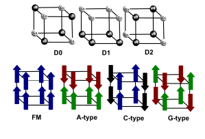
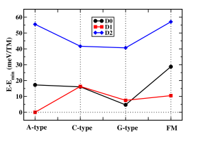
The unit cell of Cu-MOF contains four formula units. We produced the (Cu0.5Mn0.5)-MOF by replacing two of the formula units by their Mn analogues. This can result in three kinds of cation ordering (D0, D1 and D2) as shown in Figure 1(a). For each cation ordered structure we also investigated different collinear magnetic ordering of the Mn (5 ) and Cu (1 ) spin moments (see Figure 1(a)). These included three AFM arrangements (A, C, and G-type) and the ferromagnetic arrangement (FM). The optimized energies for the various structures considered are summarized in the plot shown in Figure 1(b). The lowest energy structure consists of layers of Mn and Cu alternating along the c-axis with an A-type AFM arrangement of spins (referred to below as D1-A). A structure with rock-salt ordering of the TM ions and with a G-type AFM arrangement of their spins (referred to below as D0-G), was found to be higher in energy than D1-A by just 4.75 meV/TM. Starting from the experimental structure of Mn-MOF (\ce[C(NH2)3][Mn(HCOO)3]) (), we have computed the ground state of Mn-MOF to be G-type AFM. To the best of our knowledge, the ground magnetic state of the MOF has not been reported earlier. We used the predicted ground state of Mn-MOF for the calculation of formation energy. The formation energies computed for the D1-A and D0-G structures (-101 and -96.25 meV/TM, respectively) suggest that both can likely be synthesized. We focus on these two structures as they are magnetic in nature with moments comparable to inorganic compounds as shown below.
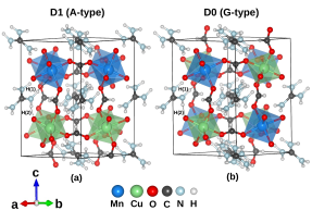
Figure 2(a) shows the structure of the (Cu0.5Mn0.5)-MOF in the ground-state. Each TM ion in the MOF is surrounded by six \ceHCOO- anions forming a distorted octahedra. The near cubic cavities are occupied with \ce[C(NH2)3]+ groups providing charge balance in the compound. Like the parent Cu-MOF, each distorted Cu-O octahedron possesses two short ( 2.02, 1.99) and two long (2.44, 2.36) equatorial Cu-Oeq bonds; and two medium (2.04, 2.02) axial Cu-Oax bonds. The Mn-O octahedra, with two long (2.22, 2.22) and two short (2.17, 2.21) equatorial bonds, are only slightly distorted. Thus, the Mn-O octahedra in D1-A closely resemble those in the parent Mn-MOF which crystallizes in a non-polar Pnna space-group. In the case of D0-G (Figure 2(b)), the bond-length variation around the Cu is the same as in D1-A. However, unlike in D1-A, the octahedra around Mn are strongly distorted with two short (2.03, 2.06), two long (2.18, 2.23) and two medium (2.08, 2.10) bonds. This is in contrast with the parent Mn-MOF where octahedral distortions arise only when the A site cation is changed Wang et al. (2004). Thus, compared to D0-G, D1-A is more stable since its layered structure allows the Mn-O octahedra to retain the undistorted structure seen in the parent.
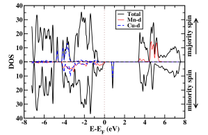
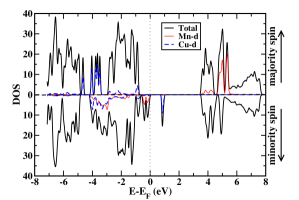
The magnetic TM ions in the structure, linked by formate groups, interact with each other through long-distance super-exchange Tian et al. (2014) mechanism. The density-of-states (DOS) plots for both D0 and D1 structure (see Figure 3) show Mn to be in the high-spin Mn2+ () and Cu to be in the Cu2+ () valence configurations. The valence configurations are also confirmed by the -projected occupation numbers (not mentioned here). In both cases, the hole state from Cu forms a narrow band indicating spatial localization. Figure 3 clearly shows that the D1-A and D0-G MOFs are ferrimagnetic insulators with a narrow band gap of 0.8 and 0.9 eV, respectively. The DOS also reflects the AFM ordering in the structure. Partial cancellation of moments between the two TM ions leads to a net magnetic moment of 4 per Cu-Mn pair (or 2 /TM) in both D1-A and D0-G. The predicted value is comparable to inorganic ferromagnets and higher than those generally seen in magnetic MOFs. In D1-A, the FM interaction in the Cu layer arises due to the AFO ordering of the Cu -orbitals caused by the Jahn-Teller (JT) effect Stroppa et al. (2011). As a result, the hole in Cu alternates between the two orbitals from one Cu to its nearest neighbour, an effect also seen in the parent Cu-MOF. FM super-exchange interaction is mediated via a half-filled orbital on a Cu and a completely filled one on its neighbour in the same layer, as predicted by the Goodenough-Kanamori (GK) Goodenough (1963) rules. Surprisingly, however, the Mn layer also displays FM order defying the GK rules for a TM ion pair. Moreover, in the D0-G case, despite the octahedral distortions around both TM ions, only AFM interactions prevail.
The predicted magnetic states for D0 and D1 structures can be rationalized with the help of the exchange coupling constants for all TM pairs in the structures. These parameters can be extracted by mapping the DFT computed energies of the various magnetic configurations to a nearest-neighbour () Heisenberg Hamiltonian Rout et al. (2016). The corresponding Hamiltonians for the D0 and D1 supercells along with a detailed description of the method of extracting the coupling constants is presented in the SI. Taking the -plane as reference, the D0 structure has an inter- () and an intra-plane () Cu-Mn coupling constants. These were calculated to be 4.6 meV and 2.53 meV, respectively. In D1-A, there are two in-plane ( -0.9 meV, -0.5 meV) and one out-of-plane ( 3.9 meV) coupling constants. We note that the Cu-Mn interactions are strongly AFM, consistent with the GK rules for a pair. Thus we get a G-type AFM ordering for the D0 structure irrespective of the JT distortions around Cu.
In D1, the strong out-of-plane AFM exchange along with the AFO-driven FM ordering in the Cu layer, drives the Mn layer to be FM. This leads to the predicted A-type AFM ground state. The FM coupling between Cu ions is key to establishing such a ground-state. To confirm this surprising result, we extended the range of coupling in the model used for the D1 structure to the next-nearest neighbour () Cu-Mn interactions and recomputed the coupling constants. This did not affect the Mn-Mn FM coupling much (-0.52 meV) but instead significantly enhanced the Cu-Cu FM coupling to -1.71 meV.
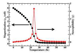
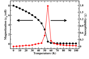
From the magnitude of the coupling constants we anticipated a significant increase in the magnetic transition temperature () as the coupling constant is directly proportional Evans et al. (2014) to . Using classical Monte-Carlo simulations (see SI for details), we can predict the for the Pna21-like phase of (Cu0.5Mn0.5)-MOF. Figure 4 shows the magnetic moment as well as the magnetic susceptibility plotted as a function of temperature for both structures. The plots indicate that the magnetic transition occurs at 24 K and 56 K for D1-A and D0-G, respectively. Thus the could be pushed up to K through this mixed metal strategy. The predicted is a remarkable increase over that of the parent compound and is indicative of the enhanced stability of the ferrimagnetic phase in the (Cu0.5Mn0.5)-MOF relative to most other magnetic MOFs seen so far. The estimates given here are based on the Heisenberg model. In the case of D1, use of the coupling constants based on the model yielded a K (see SI).
First-principles calculations on Cu-MOF have estimated a c-axis electric polarization of 0.37 Stroppa et al. (2011), while Mn-MOF was found to crystallize in a non-polar structure Hu et al. (2009). It has been suggested that the weak polarization can be tuned by varying the organic A-site cation Sante et al. (2013) or by strain field Ghosh et al. (2015). Indeed, [\ceCH3CH2NH3][Mn(HCOO)3] was found to yield a theoretical polarization of 1.6 C/cm2 Sante et al. (2013) with some contribution arising from octahedral distortion around Mn cations. While the B-site mixing strategy proposed here was aimed mainly at improving the magnetic moments, we also investigated the polarization of the predicted compounds. We calculated the electric polarization using a Berry phase approach King-Smith and Vanderbilt (1993) ensuring the convergence of the computed numbers with the relevant parameters (see SI). Surprisingly, we found that both D0-G and D1-A yielded a significantly enhanced c-axis polarization of -9.93 and -9.77 C/cm2, respectively, than that (0.37 ) in the parent Cu-MOF. We obtained the polarization as a difference between the polar () and non-polar () structures. Note that the polarization difference computed this way is one value in a lattice of values spaced by the polarization quantum. However, the actual value can be fixed by looking at the changes in the Berry phase along a smooth path connecting the polar and non-polar structures.
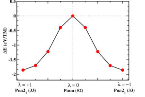
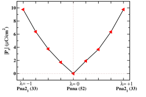
We constructed various structures linearly interpolated between polar (Pna21-like) and the paraelectric phases. The latter was assumed to be the non-polar Pnna-like centro-symmetric structure Kroumova et al. (2001); Orobengoa et al. (2009). The structures along the interpolation were followed using a parameter , measuring the amplitude of the displacement, with values for the polar and for the non-polar centric forms, respectively. Figure 5 depicts the interpolation thus done in the D1-A structure. The maximum atomic displacement between and was found to be about . The variation in energy of D1-A along an idealized polarization switching path through the non-polar intermediate is shown in Figure 5(a). The polar phase of D1-A is more stable that the centric phase by eV/TM. In Figure 5(b), we have plotted the ferroelectric polarization along the polar -axis as a function of . The polarization calculated from this plot is found to be . A similar approach was also followed for the D0-G structure resulting in an energy difference of eV/TM between the polar and non-polar phases (see Figure in SI). A polarization of was computed in this case from a 2-point Berry phase formula.
The large energy differences between the polar and centric structures noted above suggest insurmountable ferroelectric switching barriers. However, this interpretation is not always warranted. While we have considered an idealized path for the ferroelectric switching, this may not necessarily be the path followed by the system in reality. For instance, the barrier for the ground state D1-A structure is reduced to 1.2 eV, when we optimize the cell parameters of the Pnna structure keeping the ions in their centro-symmetric positions. The resulting orthorhombic unit cell (see SI) hints at a structural phase transition accompanying the polarization switching. Furthermore, the barrier calculated here is a single domain switching barrier. In practice, however, the ferroelectric switching barrier can be significantly lowered by presence of domains Jo et al. (2006); Bratkovsky and Levanyuk (2000) not considered in the present calculation. Indeed, recently, Somdutta et al. have experimentally shown ferroelectric switching in \ceGaFeO3 thin-films although the bulk form was theoretically predicted to have high polarization switching barrier Mukherjee et al. (2013). They have attributed the reduction of ferroelectric barriers to the presence of ferroelectric domains in these samples. The higher the nucleation of domains the more the reduction of thermally insurmountable single-domain switching barrier Jo et al. (2006). Similar effects could, in principle, also lower the switching barriers in the predicted MOF which can be verified through experimental realization of the system.
In Cu-MOF, it was shown Stroppa et al. (2011) that the displacements of \ceNH2 groups of the guanidinium cations result in the dominant contribution to the ferroelectric polarization. In contrast, in the ground-state of the (Cu0.5Mn0.5)-MOF, we found that the larger contribution arises from the \ceBX3 group instead of A-site. In order to estimate their relative magnitudes, we calculated the polarization arising from A-site displacements (PA) and displacement of atoms belonging to the functional group \ceBX3 (P) separately by displacing each group towards its polar configuration keeping the others fixed in the non-polar geometry. We found the values P 0.21 and P -7.36 , respectively, indicating that the major contribution is made by the distortions at the \ceBX3-site. The estimated polarization value of A-site cation ion is in excellent agreement with the previously estimated value (0.21) of the parent Cu-MOF Stroppa et al. (2011). The significantly larger polarization arising from the \ceBX3 framework in this case is clearly due to the presence of the non-JT Mn ions which were absent in the parent Cu-MOF. The discrepancy between the polarization estimated from these contributions (-7.2 ) and the exact value is likely due to the neglect of relaxation effects in the former.
In order to further support our Berry phase results, we have calculated the ferroelectric polarization from the dipole moments contributed from each A-site and \ceBX3 group by using a non-periodic, localized basis code Frisch et al. (2009) (see SI Table VI for details). We found the polarization values to be P 0.18 and P-5.13 , respectively. These values mirror the contributions seen in the Berry phase approach and once again confirm that the major contribution to the total polarization arises from the distortion of \ceBX3 groups. We also applied the method to estimate the contributions to the polarization in the Cu-MOF. The results (see SI) confirmed that the dipole moments arising from the \ceBX3 groups significantly increase in the mixed metal MOF compared to the parent Cu-MOF while there was no change in the moments at the A-site.
The existence of magnetoelectric coupling has been demonstrated in the parent MOF and is an important ingredient for applicability of these materials. In order to test for the coupling in the mixed metal MOF, we also performed DFT++vdW calculations incorporating spin-orbit coupling on the D1-A and D0-G structures. The resulting magnetization values are summarized in Table 1. The magnetization along the -axis was not affected (4.0 per TM pair) but it developed components in the -plane of magnitude 0.01 per TM pair. Inverting the direction of the polarization leads to retention of the -axis component but inversion of the component in the -plane. So there is indeed a magneto-electric effect confined to the -plane similar to the case of the parent MOF. The magnitude of the moments are slightly reduced by mixing in Mn ions as it is the JT-active Cu ions in the system which mostly contribute to the ME coupling (see Table V-VIII in SI). Thus, the mixing in of non-JT ions leads to an apparent suppression of the magnetoelectric effect.
| D1-A type | D0-G type | |
|---|---|---|
| Distortion | mx my mz | mx my mz |
| -0.02 0.00 -8.01 | -0.03 -0.01 -8.01 | |
| 0.01 0.01 -8.01 | 0.00 0.01 -8.01 |
In conclusion, we have designed, from first-principles, a mixed metal perovskite MOF, [C(NH2)3][(Cu0.5Mn0.5)(HCOO)3] with significantly enhanced magnetization and a polarization compared to its parent Cu-MOF as well as other mixed metal MOFs synthesized so far Maczka et al. (2016). We also predict that the ground state MOF would have a magnetic transition temperature of around 24 K which can be enhanced up to 56 K by altering the cation ordering in the B-site. This is a remarkable improvement over multiferroic MOFs synthesized so far. Our calculations indicate large formation enthalpies for the compound in two lowest energy structures suggesting feasibility of laboratory synthesis. The ground-state structure is composed of layers of Mn and Cu alternating along the c-axis. A strong AFM Cu-Mn exchange coupling along with FM ordering in the Cu layer, driven by Jahn-Teller distortion, forces FM coupling in the Mn layer as well. This results in an A-type AFM ordered state with a magnetic moment of 2 /TM. Changes in hydrogen-bonds at the A-site, distortions of the oxygen octahedra around Cu and Mn, as well as displacements of the formates contribute to the polarization enhancement. The competing magnetic interactions between the Cu and Mn layers suggest the possibility of magnetic and structural transitions with variation of relative composition Evans et al. (2016) of the two TM ions as well as epitaxial strain. These will be the subjects of a future study.
Our choice of the TM ions as well as the feasibility of the mixed metal approach are motivated by the facts that, (i) polar [\ceC(NH2)3][Cu(HCOO)3] and [\ceCH3CH2NH3][Mn(HCOO)3] have already been experimentally synthesized, and (ii) very recently Evans et al. (2016), a mixed metal MOF with the same framework has been synthesized. Therefore, we expect that [C(NH2)3][(Cu0.5Mn0.5)(HCOO)3] can also be realized. The strategy can be used to further explore other metal combinations in the () structure, along with variations in their compositions, to engineer the magnetic, electric Evans et al. (2016) and even elastic Li et al. (2013) properties in this class of MOFs.
Acknowledgements.
The authors would like to thank all the members of AIT group of IISER Bhopal for valuable discussions. The authors gratefully acknowledge Indian Institute of Science Education and Research Bhopal HPC facility for computational resources. P.C.R. would like to acknowledge CSIR-HRDG for funding through CSIR-JRF programme.References
- Cheong and Mostovoy (2007) S. W. Cheong and M. Mostovoy, Nat. Mater. 6, 13 (2007).
- Ramesh (2009) R. Ramesh, Nature 461, 1218 (2009).
- Picozzi and Ederer (2009) S. Picozzi and C. Ederer, J. Phys. Condens. Matter 21, 303201 (2009).
- Tokura and Seki (2010) Y. Tokura and S. Seki, Adv. Mater. 22, 1554 (2010).
- Brink and Khomskii (2008) J. Brink and D. Khomskii, J. Phys. Condens. Matter 20, 434217 (2008).
- Ma et al. (2011) J. Ma, J. M. Hu, Z. Li, and C. W. Nan, Adv. Mater. 23, 1062 (2011).
- Wang et al. (2009) K. F. Wang, J. M. Liu, and Z. Ren, Adv. Phys. 58, 321 (2009).
- Lee et al. (2010) J. H. Lee, L. Fang, E. Vlahos, X. Ke, Y. W. Jung, L. F. Kourkoutis, J.-W. Kim, P. J. Ryan, T. Heeg, M. Roeckerath, et al., Nature 466, 954 (2010).
- Rosseinsky (2010) M. J. Rosseinsky, Nat. Mater. 9, 609 (2010).
- Xu et al. (2011) G. C. Xu, W. Zhang, X. M. Ma, Y. H. Chen, L. Zhang, H. L. Cai, Z. M. Wang, R. G. Xiong, and S. Gao, J. Am. Chem. Soc. 133, 14948 (2011).
- Stroppa et al. (2013) A. Stroppa, P. Barone, P. Jain, J. M. Perez-Mato, and S. Picozzi, Advanced Materials 25, 2284 (2013).
- Ferrey (2008) G. Ferrey, Chem. Soc. Rev. 37, 191 (2008).
- Stroppa et al. (2011) A. Stroppa, P. Jain, P. Barone, M. Marsman, J. M. Perez-Mato, A. K. Cheetham, H. W. Kroto, and S. Picozzi, Angew. Chem Int. Ed. 50, 5847 (2011).
- Jain et al. (2009) P. Jain, V. Ramachandran, R. J. Clark, H. D. Zhou, B. H. Toby, N. S. Dalal, H. W. Kroto, and A. K. Cheetham, J. Am. Chem. Soc. 131, 13625 (2009).
- Demir et al. (2012) S. Demir, J. M. Zadrozny, M. Nippe, and J. R. Long, J. Am. Chem. Soc. 134, 18546 (2012).
- Sante et al. (2013) D. D. Sante, A. Stroppa, P. Jain, and S. Picozzi, J. Am. Chem. Soc. 135, 18126 (2013).
- Hu et al. (2009) K. L. Hu, M. Kurmoo, M. Wang, and S. Gao, Chem. Eur. J. 15, 12050 (2009).
- Baettig and Spaldin (2005) P. Baettig and N. A. Spaldin, Appl. Phys. Lett. 86, 012505 (2005).
- Baettig et al. (2005) P. Baettig, C. Ederer, and N. A. Spaldin, Phys. Rev. B 72, 214105 (2005).
- Ciupa et al. (2015a) A. Ciupa, M. Maczka, A.Gagor, A. Seiradzki, J. Trzmiel, A. Pikul, and M. Ptak, Dalton Trans. 44, 8846 (2015a).
- Ciupa et al. (2015b) A. Ciupa, M. Maczka, A.Gagor, A. Pikul, and M. Ptak, Dalton Trans. 44, 13234 (2015b).
- Mazzuca et al. (2017) L. Mazzuca, L. Cañadillas Delgado, J. A. Rodríguez-Velamazán, O. Fabelo, M. Scarrozza, A. Stroppa, S. Picozzi, J.-P. Zhao, X.-H. Bu, and J. Rodríguez-Carvajal, Inorganic Chemistry 56, 197 (2017), http://dx.doi.org/10.1021/acs.inorgchem.6b01866 .
- Zhao et al. (2010) J.-P. Zhao, B.-W. Hu, F. Lloret, J. Tao, Q. Yang, X.-F. Zhang, and X.-H. Bu, Inorganic Chemistry 49, 10390 (2010).
- Evans et al. (2016) N. L. Evans, P. M. M. Thygesen, H. L. B. Bostrom, E. M. Reynolds, I. E. Collings, A. E. Phillips, and A. L. Goodwin, J. Am. Chem. Soc. 138, 9393 (2016).
- Shang et al. (2012) R. Shang, X. Sun, Z.-M. Wang, and S. Gao, Chemistry : An Asian Journal 7, 1697 (2012).
- Maczka et al. (2016) M. Maczka, A. Gagor, K. Hermanowicz, A. Sieradzki, L. Macalik, and A. Pikul, Journal of Solid State Chemistry 237, 150 (2016).
- Perdew et al. (1996) J. P. Perdew, K. Burke, and M. Ernzerhof, Phys. Rev. Lett. 77, 3865 (1996).
- Perdew et al. (1997) J. P. Perdew, K. Burke, and M. Ernzerhof, Phys. Rev. Lett. 78, 1396 (1997).
- Anisimov et al. (1997) V. I. Anisimov, F. Aryasetiawan, and A. I. Liechtenstein, J. Phys. Condens. Matter 9, 767 (1997).
- Cococcioni and de Gironcoli (2005) M. Cococcioni and S. de Gironcoli, Phys. Rev. B 71, 035105 (2005).
- Himmetoglu et al. (2011) B. Himmetoglu, R. M. Wentzcovitch, and M. Cococcioni, Phys. Rev. B 84, 115108 (2011).
- Kulik et al. (2006) H. J. Kulik, M. Cococcioni, D. A. Scherlis, and N. Marzari, Phys. Rev. Lett. 97, 103001 (2006).
- Kulik and Marzari (2011) H. J. Kulik and N. Marzari, J. Chem. Phys. 134, 094103 (2011).
- Kulik and Marzari (2010) H. J. Kulik and N. Marzari, J. Chem. Phys. 133, 114103 (2010).
- Grimme (2004) S. Grimme, J. Comput. chem. 25, 1463 (2004).
- Giannozzi et al (2006) P. Giannozzi et al, J. Phys. Condens. Mater. 21, 395502 (2006).
- Wang et al. (2004) Z. Wang, B. Zhang, T. Otsuka, K. Inoue, H. Kobayashi, and M. Kurmoo, Dalton Trans. , 2209 (2004).
- Tian et al. (2014) Y. Tian, W. Wang, Y. Chai, J. Cong, S. Shen, L. Yan, S. Wang, X. Han, and Y. Sun, Phys. Rev. Lett. 112, 017202 (2014).
- Goodenough (1963) J. B. Goodenough, Magnetism and Chemical Bond , Interscience Publ., New York (1963).
- Rout et al. (2016) P. C. Rout, A. Putatunda, and V. Srinivasan, Phys. Rev. B 93, 104415 (2016).
- Evans et al. (2014) R. F. L. Evans, W. J. Fan, P. Chureemart, T. A. Ostler, M. O. A. Ellis, and R. W. Chantrell, J. Phys. Condens. Matter 26, 103202 (2014).
- Ghosh et al. (2015) S. Ghosh, D. D. Sante, and A. Stroppa, J. Phys. Chem. L 6, 4553 (2015).
- King-Smith and Vanderbilt (1993) R. D. King-Smith and D. Vanderbilt, Phys. Rev. B 47, 1651 (1993).
- Kroumova et al. (2001) E. Kroumova, M. I. Aroyo, J. M. Perez-Mato, S. Ivantchev, J. M. Igartua, and H. Wondratschek, J. Appl. Crystallogr. 34, 783 (2001).
- Orobengoa et al. (2009) D. Orobengoa, C. Capillas, M. I. Aroyo, and J. M. Perez-Mato, J. Appl. Crystallogr. 42, 840 (2009).
- Jo et al. (2006) J. Y. Jo, D. J. Kim, Y. S. Kim, S.-B. Choe, T. K. Song, J.-G. Yoon, and T. W. Noh, Phys. Rev. Lett. 97, 247602 (2006).
- Bratkovsky and Levanyuk (2000) A. M. Bratkovsky and A. P. Levanyuk, Phys. Rev. Lett. 85, 4614 (2000).
- Mukherjee et al. (2013) S. Mukherjee, A. Roy, S. Auluck, R. Prasad, R. Gupta, and A. Garg, Phys. Rev. Lett. 111, 087601 (2013).
- Frisch et al. (2009) M. Frisch, G. Trucks, H. Schlegel, G. Scuseria, M. Robb, J. Cheeseman, G. Scalmani, V. Barone, B. Mennucci, G. Petersson, et al., GAUSSIAN09. Gaussian Inc., Wallingford, CT, USA (2009).
- Li et al. (2013) W. Li, Z. Zhang, E. G. Bithell, A. S. Batsanov, P. T. Barton, P. J. Saines, P. Jain, C. J. Howard, M. A. Carpenter, and A. K. Cheetam, Acta Materialia 61, 4928 (2013).