Determination of the magnetic structure of CePt2In7 by means of neutron diffraction
Abstract
The magnetic structure of the heavy fermion antiferromagnet CePt2In7 is determined using neutron diffraction. We find a magnetic wave vector , which is temperature independent up to 5.5 K. A staggered moment of 0.45(1) at 2 K resides on the Ce ion. The nearest-neighbor moments in the tetragonal basal plane are aligned antiferromagnetically. The moments rotate by 90∘ from one CeIn3 plane to another along the axis. A much weaker satellite peak with an incommensurate magnetic wave vector seems to develop at low temperature. However, the experimental data available so far are not sufficient to draw a definitive conclusion about the possible co-existence of commensurate and incommensurate magnetic structures in this material.
CePt2In7 is a recently discovered heavy fermion compound that belongs to the same family as the well-studied CeIn3 and CeIn5 ( Co, Rh, Ir). The spacing between Ce-In planes in CePt2In7 is drastically increased Klimczuk et al. (2014) as compared to its CeIn5 counterparts, implying a more two-dimensional crystal structure. Expectedly, the Fermi surface of CePt2In7 is also much more two dimensional Altarawneh et al. (2011). This compound crystallizes in the body-centered-tetragonal structure (space group ) with a unit cell considerably elongated along the axis.
CePt2In7 undergoes an antiferromagnetic (AF) transition at 5.5 K Tobash et al. (2012); Bauer et al. (2010a); apRoberts Warren et al. (2010, 2012). Recent electrical resistivity and ac-calorimetry measurements under pressure on single crystals of CePt2In7 revealed a quantum critical point at a critical pressure 3.2 GPa, where the AF order is completely suppressed Sidorov et al. (2013). A superconducting dome with the highest transition temperature 2.1 K is observed around Sidorov et al. (2013); Bauer et al. (2010b, a), suggesting that critical AF fluctuations may mediate the Cooper pairing. Nuclear magnetic and quadrupole resonance (NMR and NQR, respectively) measurements on single crystals under pressure Sakai et al. (2014) suggest that is not the only relevant pressure for this material. Indeed, a localized to itinerant crossover of the 4 electron of Ce occurs within the AF state at 2.4 GPa, approximately the pressure where superconductivity first emerges in single crystals.
While the magnetic structure of the cubic CeIn3 is characterized by a simple commensurate ordering wave vector Lawrence and Shapiro (1980); Benoit et al. (1980), that of the more two-dimensional CeRhIn5 is more complicated. Its magnetically ordered ground state is an incommensurate helicoidal phase with the propagation vector and the magnetic moment in the basal plane of the tetragonal structure Bao et al. (2000, 2003); Raymond et al. (2007, 2014); Fobes et al. (2017).
In CePt2In7, the magnetic structure of its AF ground state is still an open question. The existing reports on this matter are controversial. Indeed, NQR studies performed on polycrystalline samples apRoberts Warren et al. (2010) suggest that antiferromagnetism is commensurate in this material. The same conclusion was drawn from positive muon-spin rotation and relaxation (SR) measurements also performed on polycrystalline samples Månsson et al. (2014). On the contrary, the NQR spectra obtained on single crystals are consistent with the coexistence of an incommensurate and commensurate AF component of the magnetic structure Sakai et al. (2011, 2014). The commensurate AF order first occurs just below , then, at lower temperatures of about 3 K, incommensurate AF order gradually grows in. This probably accounts for the observation of only commensurate magnetism in polycrystalline NQR measurements, which were performed at temperatures down to 4 K apRoberts Warren et al. (2010). At 1.6 K, the volume fraction of the incommensurate order is about 75%. However, the commensurate AF order is stabilized by hydrostatic pressure: Its volume fraction becomes nearly 100% at 2.4 GPa, the pressure where superconductivity first occurs and electrons change from localized to itinerant. All the NQR experiments apRoberts Warren et al. (2010); Sakai et al. (2011, 2014) lead to the same conclusion: The magnetic propagation vector is , although the value of is not predicted.
In this Rapid Communication, we report the magnetic structure of CePt2In7 determined from neutron diffraction, which is a bulk probe contrary to NQR and SR measurements. The magnetic structure is found to be commensurate with a magnetic propagation vector (1/2, 1/2, 1/2). The magnetic moments are aligned antiferromagnetically in the basal plane, and rotate by 90∘ from one CeIn3 plane to another. As expected, the magnetic structure is more two dimensional than those of either CeIn3 or CeRhIn5.
Single crystals of CePt2In7 were grown by the In self-flux method, as explained in more detail elsewhere Kurahashi et al. (2015). The high quality of the samples is confirmed by specific heat measurements that show a clear and unique second-order phase transition at the Néel temperature 5.5 K Krupko et al. (2016) and de Haas-van Alphen effect measurements exhibiting quantum oscillations starting from about 2 T Götze et al. . Two neutron diffraction experiments were performed at the Institut Laue-Langevin (ILL) of Grenoble (France) to determine the AF structure of CePt2In7. At first, a powder neutron diffraction was carried out on the high-flux diffractometer D1B by using a pyrolytic graphite (002) monochromator providing a beam with a wavelength of 2.52 Å and a 128∘ multidetector. A great number of single crystals was ground into 1.6 g of fine powder. These measurements did not reveal any magnetic peaks below TN in spite of 10-h-long acquisitions at both 1.5 and 10 K. This puts an upper limit for the magnetic moment at about 0.8. Both the crystal structure and the lattice parameters remain unchanged in the AF state. Similarly, no temperature-dependent magnetic peaks were detected in the previous powder neutron diffraction measurements on CeRhIn5 Bao et al. (2000). Following this, a preliminary single-crystal neutron diffraction experiment was performed on the D23 beamline. This test measurement revealed a magnetic peak with , leading to more detailed measurements on the D10 beamline. For this experiment, we examined the biggest available sample from the same batch with the dimensions mm3 and the axis perpendicular to the platelet surface. The instrument was used in a four-circle configuration with an additional triple-axis energy analysis. The latter was used in the elastic mode with a single detector to increase the signal-to-noise ratio. A vertically focusing pyrolytic graphite monochromator and analyzer was employed, fixing the incident and analyzed wavelength to 2.36 Å. A pyrolytic graphite filter was used to reduce the higher harmonic contamination to of the primary beam intensity. In order to reach temperatures down to 2 K, we used a four-circle cryostat with helium circulation. The measured lattice parameters at 2 K are 4.595(2) Å and 21.558(5) Å, as obtained from the analysis of 30 nuclear Bragg peaks.
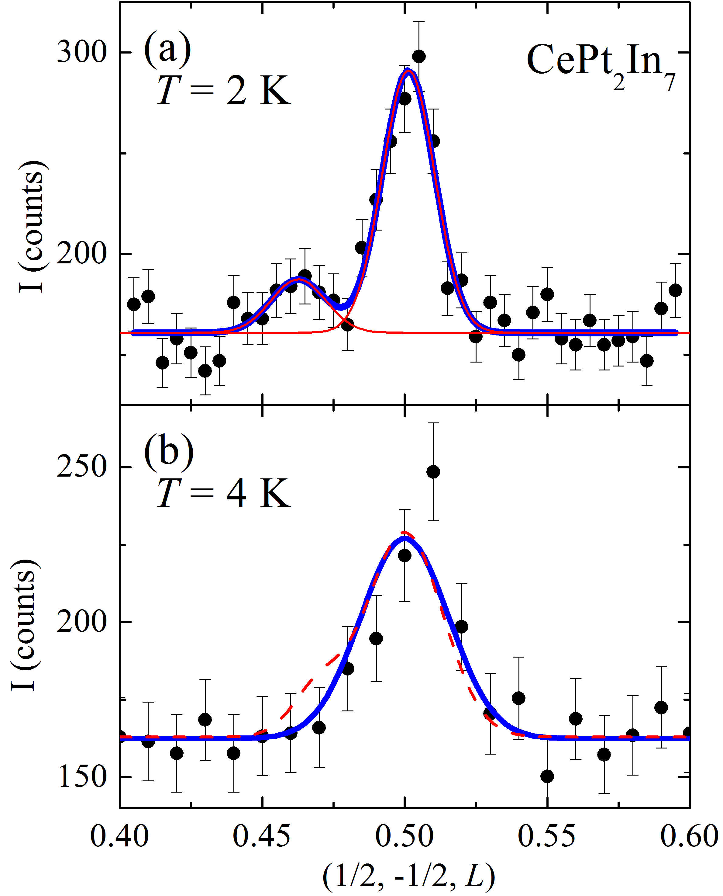
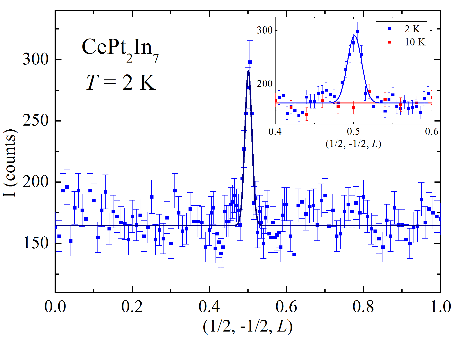
Figure 1 shows the scan performed along the [001] direction at 2 K. A clear peak is observed at . As expected, the Bragg peak disappears above the Néel temperature, as shown in the inset of Fig. 1 for 10 K. Below , the value of the propagation vector does not seem to change with temperature. However, the full width at half maximum (FWHM) of the magnetic peak increases with temperature (see Fig. 2), suggesting a smaller size of magnetic domains along the axis for temperatures close to . We did not observe any other obvious peaks with an incommensurate magnetic wave vector. However, a small satellite peak at (1/2, 1/2, 1/2-) with =0.03 seems to emerge above the background noise at 2 K, as shown in Fig. 2(a). The integrated intensity of this peak is 21% of the commensurate magnetic Bragg peak. The satellite peak seems to disappear at 4 K, as an attempt to fit the data by two Gaussian peaks with the fixed position of the incommensurate peak and integrated intensity ratio of the two peaks does not yield a satisfactory result [see Fig. 2(b)]. Remarkably, the NQR measurements performed on single crystals suggest the presence of only a commensurate order at 4 K, whereas an incommensurate order starts to develop below about 3 K Sakai et al. (2011, 2014). However, these measurements also suggest that the volume fraction of the incommensurate order is almost 3/4 at 2 K, and that the internal field due to the incommensurate order is larger than that due to its commensurate counterpart. This is difficult to reconcile with our results, if the small satellite peak was a signature of an additional incommensurate order. Furthermore, if this was the case, a peak at (1/2,1/2,1/2+) should have also been observed due to the tetragonal symmetry, although not necessarily with the same intensity. Such a peak, however, is absent in our data. Therefore, for the rest of this Rapid Communication, we will neglect this tiny contribution, whose possible magnetic origin remains to be clarified.
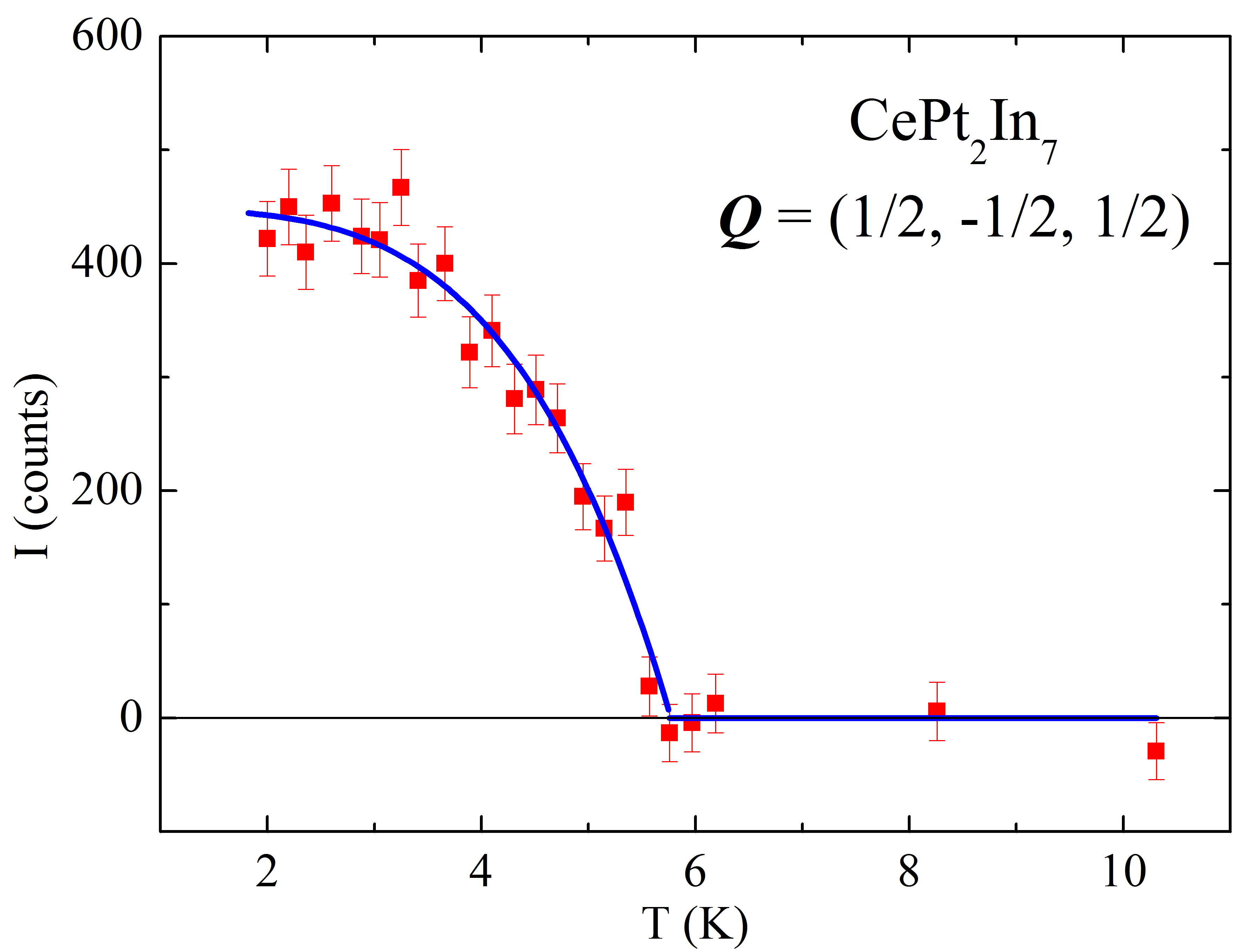
Figure 3 shows the temperature dependence of the magnetic Bragg peak intensity proportional to the square of the magnetic phase transition order parameter. To determine the Néel temperature, the data were fitted by a phenomenological function , with a free parameter, which does not have a particular physical meaning. This function was successfully used to fit the temperature dependence of the magnetic Bragg peak intensity in other heavy fermion compounds, such as CePd2Si2 van Dijk et al. (2000); Kernavanois et al. (2005) and Sn-doped CeRhIn5 Raymond et al. (2014). The best fit is obtained with and K. The latter value is consistent with determined from previous measurements Tobash et al. (2012); Bauer et al. (2010a); apRoberts Warren et al. (2010, 2012); Krupko et al. (2016).
| (1/2, -1/2, -1/2) | 8(1) | 8.2 |
| (-1/2, -1/2, -1/2) | 7(1) | 8.2 |
| (-1/2, -1/2, 1/2) | 7(1) | 8.2 |
| (1/2, -1/2, 1/2) | 7.0(9) | 8.2 |
| (1/2, -1/2, -5/2) | 10(1) | 10.6 |
| (-1/2, -1/2, -5/2) | 9(1) | 10.6 |
| (-1/2, -1/2, 5/2) | 11(1) | 10.6 |
| (1/2, -1/2, 5/2) | 9(1) | 10.6 |
| (1/2, -1/2, -3/2) | 10(1) | 9.3 |
| (-1/2, -1/2, -3/2) | 9(1) | 9.3 |
| (-1/2, -1/2, 3/2) | 8(1) | 9.3 |
| (1/2, -1/2, 3/2) | 7(1) | 9.3 |
| (1/2, -1/2, -9/2) | 12(2) | 12.0 |
| (-1/2, -1/2, -9/2) | 19(3) | 12.0 |
| (-1/2, -1/2, 9/2) | 13(2) | 12.0 |
| (1/2, -1/2, 9/2) | 15(2) | 12.0 |
| (1/2, -1/2, -7/2) | 14(2) | 11.5 |
| (-1/2, -1/2, -7/2) | 13(2) | 11.5 |
| (-1/2, -1/2, 7/2) | 12(1) | 11.5 |
| (1/2, -1/2, 7/2) | 11(2) | 11.5 |
| (1/2, -1/2, -11/2) | 15(2) | 12.0 |
| (-1/2, -1/2, -11/2) | 18.8(25) | 12.0 |
| (1/2, 1/2, 11/2) | 13(2) | 12.0 |
| (-1/2, 1/2, 11/2) | 18(3) | 12.0 |
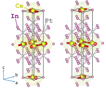
In order to determine the magnetic structure and the staggered moment, we measured 24 magnetic peaks at 2 K. For each peak, the measured neutron Bragg intensity was corrected for extinction, absorption and Lorentz factor; the resulting intensities are shown in Table 1. Only two arrangements of the magnetic moments are allowed by the group theory analysis: They can be either aligned in the basal plane or along the axis. The best refinement, taking into account two magnetic domains and assuming they are equally populated, is obtained for magnetic moments aligned antiferromagnetically in the basal plane. The moments rotate by 90∘ from one CeIn3 plane to its nearest-neighbor along the axis. For this structure, the comparison between the observed intensities and the calculated ones is shown in Table 1. Given the tetragonal symmetry of CePt2In7, we cannot determine the orientation of the magnetic moments in the basal plane. However, previous NQR data apRoberts Warren et al. (2010); Sakai et al. (2011) strongly suggest that they are parallel to the [100] direction in the commensurate phase. The resulting magnetic structure (magnetic space group ) is schematically shown in Fig. 4. The staggered magnetic moment is determined at 2 K to be per Ce.
| (Å) | (/Ce) | |||
|---|---|---|---|---|
| CeIn3 | 0 | 4.6 | 180∘ | 0.48 Benoit et al. (1980), 0.65 Lawrence and Shapiro (1980) |
| CeRhIn5 | 1 | 7.5 | 107∘ | 0.54 Fobes et al. (2017), 0.59 Raymond et al. (2007, 2014), 0.75 Bao et al. (2000, 2003) |
| CePt2In7 | 2 | 10.8 | 90∘ | 0.45 |
Having determined the magnetic structure of CePt2In7, we now consider the relationship between the magnetic and crystal structures within the CeIn3+2m ( Rh, Pt) family, where In2 layers separate a single CeIn3 layer (see Table 2). The building block of the family, CeIn3 (), crystallizes into a simple cubic structure (space group ). For CeRhIn5 () with alternating layers of CeIn3 and RhIn2, the crystal structure is primitive tetragonal (space group ). Finally, CePt2In7 (), where two PtIn2 layers separate each CeIn3 layer, crystallizes into a body-centered-tetragonal structure with space group. In all three materials, the magnetic moments of the Ce ions form a square lattice, surrounded by In ions in the plane. They all are simple, nearest-neighbor antiferromagnets in the plane. In CeIn3, the magnetic moments are also arranged antiferromagnetically along the axis. In CeRhIn5, magnetic correlations across the RhIn2 layer are incommensurate, with neighboring magnetic moments being rotated by approximately 107∘ Bao et al. (2000, 2003). In CePt2In7, the magnetic moments are also aligned in the plane. In this case, however, they rotate by 90∘ from one plane to another, as shown in Fig. 4. Clearly, the rotation angle is reduced with increasing the number of In2 layers between the CeIn3 layers (see Table 2). The magnetic structure of CePt2In7 is expected to be the most two dimensional among the three compounds. Indeed, a greater separation between the CeIn3 planes leads to a weaker coupling between them. In addition, geometrical frustration due to the body-centered-tetragonal crystal structure is likely to further reduce the effective dimensionality, as was experimentally observed in BaCuSi2O6 Sebastian et al. (2006). The 90∘ rotation angle of the moments from one plane to another observed in CePt2In7 is probably a signature of its most two-dimensional magnetic structure.
The magnetic structure of both CeIn3 and CePt2In7 is commensurate. The same conclusion was drawn for Ce2RhIn8, in which two layers of CeIn3 are separated by a single layer of RhIn2 Bao et al. (2001). This suggests CeRhIn5 with its incommensurate magnetic structure as a unique member of the whole CeIn3n+2m ( transition metal) family, where In2 layers separate CeIn3 layers. In all these compounds, superconductivity emerges in the vicinity of a quantum critical point induced either by pressure Mathur et al. (1998); Nicklas et al. (2003); Knebel et al. (2006); Sidorov et al. (2013) or chemical doping Pagliuso et al. (2001); Ohira-Kawamura et al. (2007); Yokoyama et al. (2008). Interestingly, a commensurate magnetic order was observed to either co-exist or compete with incommensurate ordering in CeRhIn5 doped with either Ir Llobet et al. (2005) or Co Ohira-Kawamura et al. (2007); Yokoyama et al. (2008). Remarkably, in these compounds, commensurate antiferromagnetism emerges in the vicinity of a quantum critical point where superconductivity also appears. Furthermore, in Sn-doped CeRhIn5, a drastic change in the magnetic order and a commensurate antiferromagnetism was observed in the proximity of the quantum critical point Raymond et al. (2014) where superconductivity is expected, but has not been observed so far. This suggests that a commensurate magnetic order might be favorable for the formation of superconductivity around a quantum critical point in this family of materials. On the other hand, several neutron diffraction experiments performed in CeRhIn5 under pressure up to 1.7 GPa did not reveal the presence of a commensurate AF order Majumdar et al. (2002); Llobet et al. (2004); Raymond et al. (2008). This pressure, however, is considerably lower than the critical value, GPa, although a pressure-induced bulk superconductivity is observed above about 1.5 GPa Knebel et al. (2006).
Regarding the staggered moment, its values are comparable for all three compounds of the CeIn3+2m family (see Table 2). Given that the staggered moment of Ce2RhIn8, 0.55/Ce Bao et al. (2001), is also of the same order, there is no obvious correlation between the staggered moment and dimensionality in this family of heavy fermion materials.
Finally, the magnetic propagation vector (1/2, 1/2, 1/2) observed both in CeIn3 and CePt2In7 implies that the magnetic Brillouin zone in these compounds is eight times smaller than the crystallographic one. In CeIn3, this naturally accounts for the observation of only small Fermi surfaces in quantum oscillation measurements performed at moderate magnetic fields up to 17 T Endo et al. (2005). Very high magnetic fields of about 55 T are required for the observation of large Fermi surfaces through magnetic breakdown tunneling Harrison et al. (2007). Similarly, only small Fermi surface pockets, well within the interior of the AF Brillouin zone, are observed in CePt2In7 at moderately high magnetic fields up to about 25-30 T Miyake et al. (2015); Götze et al. . This is in contrast with CeRhIn5, where large Fermi surfaces are observed at relatively low fields below 17-18 T Hall et al. (2001); Shishido et al. (2002).
In conclusion, we find the commensurate magnetic structure with as depicted in Fig. 4 for CePt2In7. A magnetic moment of 0.45(1) at 2 K resides on the Ce ion and the basal plane is its easy plane. Within the basal plane, magnetic moments form a simple nearest-neighbor antiferromagnet on a square lattice. The moments rotate by 90∘ from one CeIn3 plane to another along the axis.
Acknowledgements.
We thank Y. Tokunaga, M. Horvatic, and J. Robert for fruitful discussions. We acknowledge scientific and technical support we received during the powder neutron diffraction experiment on the CRG-D1B (ILL) operated by the CNRS. This work was partially supported by the ANR-DFG grant “Fermi-NESt”.References
- Klimczuk et al. (2014) T. Klimczuk, O. Walter, L. Müchler, J. W. Krizan, F. Kinnart, and R. J. Cava, J. Phys.: Condens. Matter 26, 402201 (2014).
- Altarawneh et al. (2011) M. M. Altarawneh, N. Harrison, R. D. McDonald, F. F. Balakirev, C. H. Mielke, P. H. Tobash, J.-X. Zhu, J. D. Thompson, F. Ronning, and E. D. Bauer, Phys. Rev. B 83, 081103 (2011).
- Tobash et al. (2012) P. H. Tobash, F. Ronning, J. D. Thompson, B. L. Scott, P. J. W. Moll, B. Batlogg, and E. D. Bauer, J. Phys.: Condens. Matter 24, 015601 (2012).
- Bauer et al. (2010a) E. D. Bauer, H. O. Lee, V. A. Sidorov, N. Kurita, K. Gofryk, J.-X. Zhu, F. Ronning, R. Movshovich, J. D. Thompson, and T. Park, Phys. Rev. B 81, 180507 (2010a).
- apRoberts Warren et al. (2010) N. apRoberts Warren, A. P. Dioguardi, A. C. Shockley, C. H. Lin, J. Crocker, P. Klavins, and N. J. Curro, Phys. Rev. B 81, 180403 (2010).
- apRoberts Warren et al. (2012) N. apRoberts Warren, A. P. Dioguardi, A. C. Shockley, C. H. Lin, J. Crocker, P. Klavins, and N. J. Curro, Journal of Physics: Conference Series 344, 012027 (2012).
- Sidorov et al. (2013) V. A. Sidorov, X. Lu, T. Park, H. Lee, P. H. Tobash, R. E. Baumbach, F. Ronning, E. D. Bauer, and J. D. Thompson, Phys. Rev. B 88, 020503 (2013).
- Bauer et al. (2010b) E. D. Bauer, V. A. Sidorov, H. Lee, N. Kurita, F. Ronning, R. Movshovich, and J. D. Thompson, J. Phys.: Conf. Ser. 200, 012011 (2010b).
- Sakai et al. (2014) H. Sakai, Y. Tokunaga, S. Kambe, F. Ronning, E. D. Bauer, and J. D. Thompson, Phys. Rev. Lett. 112, 206401 (2014).
- Lawrence and Shapiro (1980) J. M. Lawrence and S. M. Shapiro, Phys. Rev. B 22, 4379 (1980).
- Benoit et al. (1980) A. Benoit, J. Boucherle, P. Convert, J. Flouquet, J. Palleau, and J. Schweizer, Solid State Communications 34, 293 (1980).
- Bao et al. (2000) W. Bao, P. G. Pagliuso, J. L. Sarrao, J. D. Thompson, Z. Fisk, J. W. Lynn, and R. W. Erwin, Phys. Rev. B 62, R14621 (2000).
- Bao et al. (2003) W. Bao, P. G. Pagliuso, J. L. Sarrao, J. D. Thompson, Z. Fisk, J. W. Lynn, and R. W. Erwin, Phys. Rev. B 67, 099903(E) (2003).
- Raymond et al. (2007) S. Raymond, E. Ressouche, G. Knebel, D. Aoki, and J. Flouquet, Journal of Physics: Condensed Matter 19, 242204 (2007).
- Raymond et al. (2014) S. Raymond, J. Buhot, E. Ressouche, F. Bourdarot, G. Knebel, and G. Lapertot, Phys. Rev. B 90, 014423 (2014).
- Fobes et al. (2017) D. M. Fobes, E. D. Bauer, J. D. Thompson, A. Sazonov, V. Hutanu, S. Zhang, F. Ronning, and M. Janoschek, J. Phys.: Condens. Matter 29, 17LT01 (2017).
- Månsson et al. (2014) M. Månsson, K. Prša, Y. Sassa, P. H. Tobash, E. D. Bauer, C. Rusu, D. Andreica, O. Tjernberg, K. Sedlak, M. Grioni, T. Durakiewicz, and J. Sugiyama, J. Phys. Conf. Ser. 551, 012028 (2014).
- Sakai et al. (2011) H. Sakai, Y. Tokunaga, S. Kambe, H.-O. Lee, V. A. Sidorov, P. H. Tobash, F. Ronning, E. D. Bauer, and J. D. Thompson, Phys. Rev. B 83, 140408 (2011).
- Kurahashi et al. (2015) S. Kurahashi, S. Ota, S. Tomaru, Y. Hirose, and R. Settai, J. Phys.: Conf. Ser. 592, 012006 (2015).
- Krupko et al. (2016) Y. Krupko, A. Demuer, S. Ota, Y. Hirose, R. Settai, and I. Sheikin, Phys. Rev. B 93, 085121 (2016).
- (21) K. Götze, Y. Krupko, J. Bruin, J. Klotz, S. Ota, Y. Hirose, H. Harima, R. Settai, A. McCollam, and I. Sheikin, Unpublished.
- van Dijk et al. (2000) N. H. van Dijk, B. Fåk, T. Charvolin, P. Lejay, and J. M. Mignot, Phys. Rev. B 61, 8922 (2000).
- Kernavanois et al. (2005) N. Kernavanois, S. Raymond, E. Ressouche, B. Grenier, J. Flouquet, and P. Lejay, Phys. Rev. B 71, 064404 (2005).
- Sebastian et al. (2006) S. E. Sebastian, N. Harrison, C. D. Batista, L. Balicas, M. Jaime, P. A. Sharma, N. Kawashima, and I. R. Fisher, Nature 441, 617 (2006).
- Bao et al. (2001) W. Bao, P. G. Pagliuso, J. L. Sarrao, J. D. Thompson, Z. Fisk, and J. W. Lynn, Phys. Rev. B 64, 020401 (2001).
- Mathur et al. (1998) N. D. Mathur, F. M. Grosche, S. R. Julian, I. R. Walker, D. M. Freye, R. K. W. Haselwimmer, and G. G. Lonzarich, Nature 394, 39 (1998).
- Nicklas et al. (2003) M. Nicklas, V. A. Sidorov, H. A. Borges, P. G. Pagliuso, C. Petrovic, Z. Fisk, J. L. Sarrao, and J. D. Thompson, Phys. Rev. B 67, 020506 (2003).
- Knebel et al. (2006) G. Knebel, D. Aoki, D. Braithwaite, B. Salce, and J. Flouquet, Phys. Rev. B 74, 020501 (2006).
- Pagliuso et al. (2001) P. G. Pagliuso, C. Petrovic, R. Movshovich, D. Hall, M. F. Hundley, J. L. Sarrao, J. D. Thompson, and Z. Fisk, Phys. Rev. B 64, 100503 (2001).
- Ohira-Kawamura et al. (2007) S. Ohira-Kawamura, H. Shishido, A. Yoshida, R. Okazaki, H. Kawano-Furukawa, T. Shibauchi, H. Harima, and Y. Matsuda, Phys. Rev. B 76, 132507 (2007).
- Yokoyama et al. (2008) M. Yokoyama, N. Oyama, H. Amitsuka, S. Oinuma, I. Kawasaki, K. Tenya, M. Matsuura, K. Hirota, and T. J. Sato, Phys. Rev. B 77, 224501 (2008).
- Llobet et al. (2005) A. Llobet, A. D. Christianson, W. Bao, J. S. Gardner, I. P. Swainson, J. W. Lynn, J.-M. Mignot, K. Prokes, P. G. Pagliuso, N. O. Moreno, J. L. Sarrao, J. D. Thompson, and A. H. Lacerda, Phys. Rev. Lett. 95, 217002 (2005).
- Majumdar et al. (2002) S. Majumdar, G. Balakrishnan, M. R. Lees, D. McK. Paul, and G. J. McIntyre, Phys. Rev. B 66, 212502 (2002).
- Llobet et al. (2004) A. Llobet, J. S. Gardner, E. G. Moshopoulou, J.-M. Mignot, M. Nicklas, W. Bao, N. O. Moreno, P. G. Pagliuso, I. N. Goncharenko, J. L. Sarrao, and J. D. Thompson, Phys. Rev. B 69, 024403 (2004).
- Raymond et al. (2008) S. Raymond, G. Knebel, D. Aoki, and J. Flouquet, Phys. Rev. B 77, 172502 (2008).
- Endo et al. (2005) M. Endo, N. Kimura, and H. Aoki, J. Phys. Soc. Jpn. 74, 3295 (2005).
- Harrison et al. (2007) N. Harrison, S. E. Sebastian, C. H. Mielke, A. Paris, M. J. Gordon, C. A. Swenson, D. G. Rickel, M. D. Pacheco, P. F. Ruminer, J. B. Schillig, J. R. Sims, A. H. Lacerda, M.-T. Suzuki, H. Harima, and T. Ebihara, Phys. Rev. Lett. 99, 056401 (2007).
- Miyake et al. (2015) A. Miyake, Y. Kohama, S. Ohta, Y. Hirose, R. Settai, K. Matsubayashi, Y. Uwatoko, A. Matsuo, K. Kindo, and M. Tokunaga, J. Phys. Conf. Ser. 592, 012149 (2015).
- Hall et al. (2001) D. Hall, E. C. Palm, T. P. Murphy, S. W. Tozer, C. Petrovic, E. Miller-Ricci, L. Peabody, C. Q. H. Li, U. Alver, R. G. Goodrich, J. L. Sarrao, P. G. Pagliuso, J. M. Wills, and Z. Fisk, Phys. Rev. B 64, 064506 (2001).
- Shishido et al. (2002) H. Shishido, R. Settai, D. Aoki, S. Ikeda, H. Nakawaki, N. Nakamura, T. Iizuka, Y. Inada, K. Sugiyama, T. Takeuchi, K. Kindo, T. Kobayashi, Y. Haga, H. Harima, Y. Aoki, T. Namiki, H. Sato, and Y. Ōnuki, J. Phys. Soc. Jpn. 71, 162 (2002).