Mechanics of a granular skin
Abstract
Magic Sand, a hydrophobic toy granular material, is widely used in popular science instructions because of its non-intuitive mechanical properties. A detailed study of the failure of an underwater column of magic sand shows that these properties can be traced to a single phenomenon: the system self-generates a cohesive skin that encapsulates the material inside. The skin, consists of pinned air-water-grain interfaces, shows multi-scale mechanical properties: they range from contact-line dynamics in the intra-grain roughness scale, plastic flow at the grain scale, all the way to the sample-scale mechanical responses. With decreasing rigidity of the skin, the failure mode transforms from brittle to ductile (both of which are collective in nature) to a complete disintegration at the single grain scale.
I Introduction
Dry granular systems are known to exhibit both liquid and solid-like properties. While there are many instances where a granular assembly exhibits liquid-like properties Amarouchene et al. (2008); Cheng et al. (2007); Forterre and Pouliquen (2008); Cheng et al. (2008), examples of granular systems illustrating solid-like properties are rare with one exception: the typical conical sandpile shape de Gennes (1999). To craft more complex shapes, e.g., sand art, it is necessary to add additional constraints. These constraints can be added in the bulk or at the boundary. Adding a small quantity of water to the sand introduces constraints in the bulk in the form of capillary bridges Strauch and Herminghaus (2012); Mitarai and Nori (2006); Soulié et al. (2006); Herminghaus (2005). Conversely, encapsulating dry grains in a container is an example of constraints that are applied at the boundary Gutiérrez et al. (2015).
In general, encapsulation requires isolating materials from their surroundings and it is achieved either by (i) introducing another material in the interfacial region or (ii) facilitating processes at the interface that create self-encapsulation. Examples of the former range from the simple instance of a bag or a silo containing cereal grains to more complex examples of thin polymer films wrapping liquid droplets Py et al. (2007); Paulsen et al. (2015), texturing of liquid droplets (‘liquid marbles’) by attaching hydrophobic powder to its surface Aussillous and Quéré (2001) and stabilizing emulsions by particles or surfactants Binks and Lumsdon (2001); Dinsmore et al. (2002). In contrast, a liquid that oxidizes on contact with atmosphere to develop a stress bearing skin is an example of self-encapsulation Dickey et al. (2008).
In this paper we study the self-encapsulation of a granular system consisting of hydrophobic sand Aussillous and Quéré (2006); Abkarian et al. (2013); Subramaniam et al. (2006); Pakpour et al. (2012) under water. This system self-generates a skin which encapsulates dry hydrophobic sand-grains and stabilizes the trapped air (bubble) against the force of buoyancy. Removal of trapped air breaks down this encapsulation. The paper also explores the mechanical properties of this system at multiple scales: from the pinning of the three phase contact line at the roughness scale of the particle, plastic flow at the grain-scale, to sample-spanning mechanical responses. It may be noted here that while hydrophilic granular systems – both dry and wet – are widely studied de Gennes (1999); Hornbaker et al. (1997), hydrophobic sand grains submerged in a non-wetting liquid like water remain largely unexplored Aussillous and Quéré (2006); Abkarian et al. (2013); Subramaniam et al. (2006); Pakpour et al. (2012) even though such systems are of practical importance, especially in pharmaceutical, food and petroleum industries where newer encapsulation strategies are in great demand Saleh and Guigon (2007).
Mechanical response of a system is usually described in a small neighborhood of a reference state. For a dry granular assembly a ‘state’ of a system is described in terms of the center of mass of the grains and the forces among them. For values of strain smaller than , dry granular assembles show elastic response, i.e., the reference state can be restored by setting the applied forces to zero (see p 92 of Andreotti et al. (2013)). This elastic response comes from the reversible deformation of the region of contact between the grains. However, to describe the state of the hydrophobic sand immersed in water the information regarding the center of mass of the grains is not sufficient. We need to augment it with additional information about the detailed layout of the three phase contact lines and the local contact angles of the skin. The three phase contact lines formed at the grain-water-air interface are immobilized (pinned) by defects present in the system Moulinet et al. (2002); Quéré (2005); Quéré et al. (2003). Any additional deformation of the skin causes the contact angles to change from their reference values. This generates restoring forces in the system, i.e., if the contact angle changes from to the restoring force per unit length is , here is the surface energy at the water-air interface. The pinning and depinning of these contact lines determine the mechanical properties of the material and its mode of failure. Hence, the present study is an example of the more general problem of studying statics and dynamics of systems with elastic interfaces in a random environment Miguel and Rubi (2006).
II The hydrophobic grains and their wetting properties
As hydrophobic granular material, we use polyhedral shaped ‘Magic Sand’ grains sourced from Education Innovation Inc. (USA). They are made by coating polyhedral shaped sand grains with a hydrophobic material. Alternatively, these hydrophobic particles can be made in the laboratory by coating similar sand particles with FluoroPel PFC from Cytonix LLC silica Varshney et al. (2012).
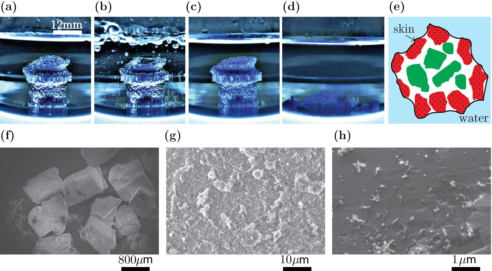
When grains of magic sand are freely poured into water, they spontaneously form a cohesive lump: a typical example of which is shown in Fig.1(a). The immediately evident features are: (i) the system retains its shape and (ii) the outer surface of the lump has a luster that originates from the total internal reflections of light at the pinned water-air interface Davis (1955); Marston (1979). On degassing of the system achieved by creating a partial vacuum over the liquid (Fig.1(b), the lump begins to lose its lustre (Fig.1(c) and when this luster-free system is mechanically perturbed, it slumps to form a flat sand-bed inside water (Fig.1(d). A cross-sectional top-view of the granular lump in Fig.1(a) is schematically shown in Fig.1(e). The grains (red coloured with dots) on the boundary together with the pinned water-interface constitute an encapsulating granular skin which provides the submerged lump its structural integrity. The force of buoyancy of the trapped air and the weight of dry sand grains in the interior (colored with green) exerts stress on the skin causing it to be under tension.
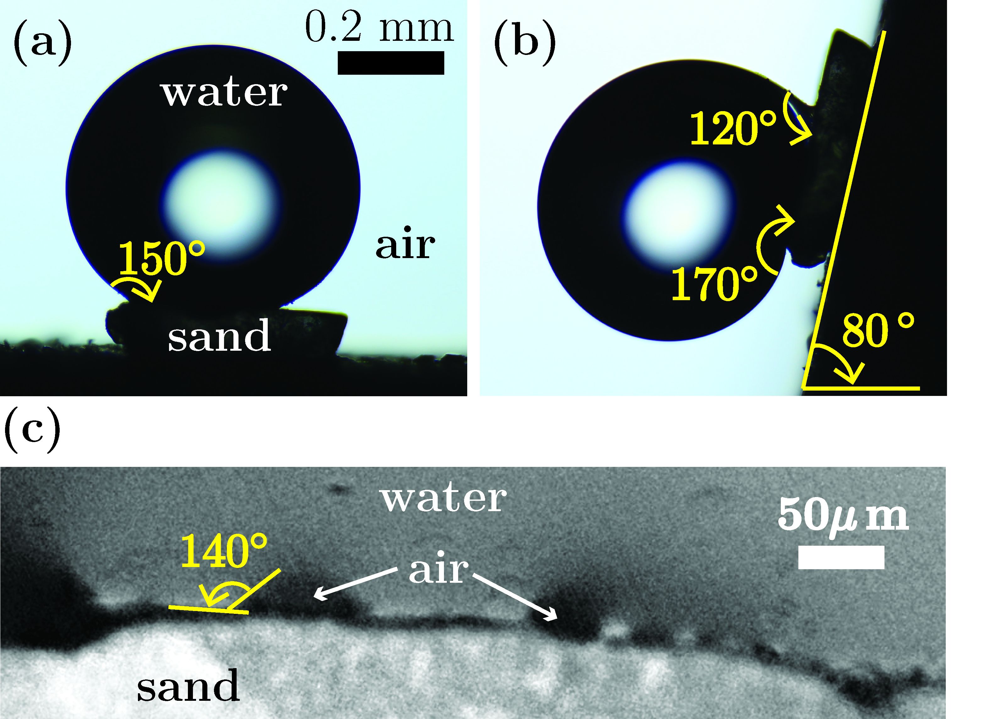
The scanning electron micrographs of the grain surface are shown in Fig.1(f) and (g), for two different values of magnification. The micron-sized rough patches (see Fig.1(g) which come from the hydrophobic coating on the particle surface are crucial for the observed wetting properties of these sand grains Quéré (2005). The equilibrium contact angle is measured to be about for a water drop placed on a single hydrophobic grain (see Fig.2(a). For the same droplet in a tilted configuration, the advancing and receding contact angles are found to be and respectively, i.e., the contact angle hysteresis is ; see Fig.2(b). The higher magnification image of water-grain interface in Fig.2(c) shows presence of small isolated air bubbles trapped between the grain and the water which have similar equilibrium contact angles , i.e., the surrounding water is in partial contact with the hydrophobic sand grains which creates a Wenzel type wetting scenario Quéré et al. (2003); Quéré (2005). Washing these grains in acetone removes the hydrophobic coating and exposes the underlying smooth hydrophilic surface (Fig.1(h).
III Construction of a submerged free-standing column
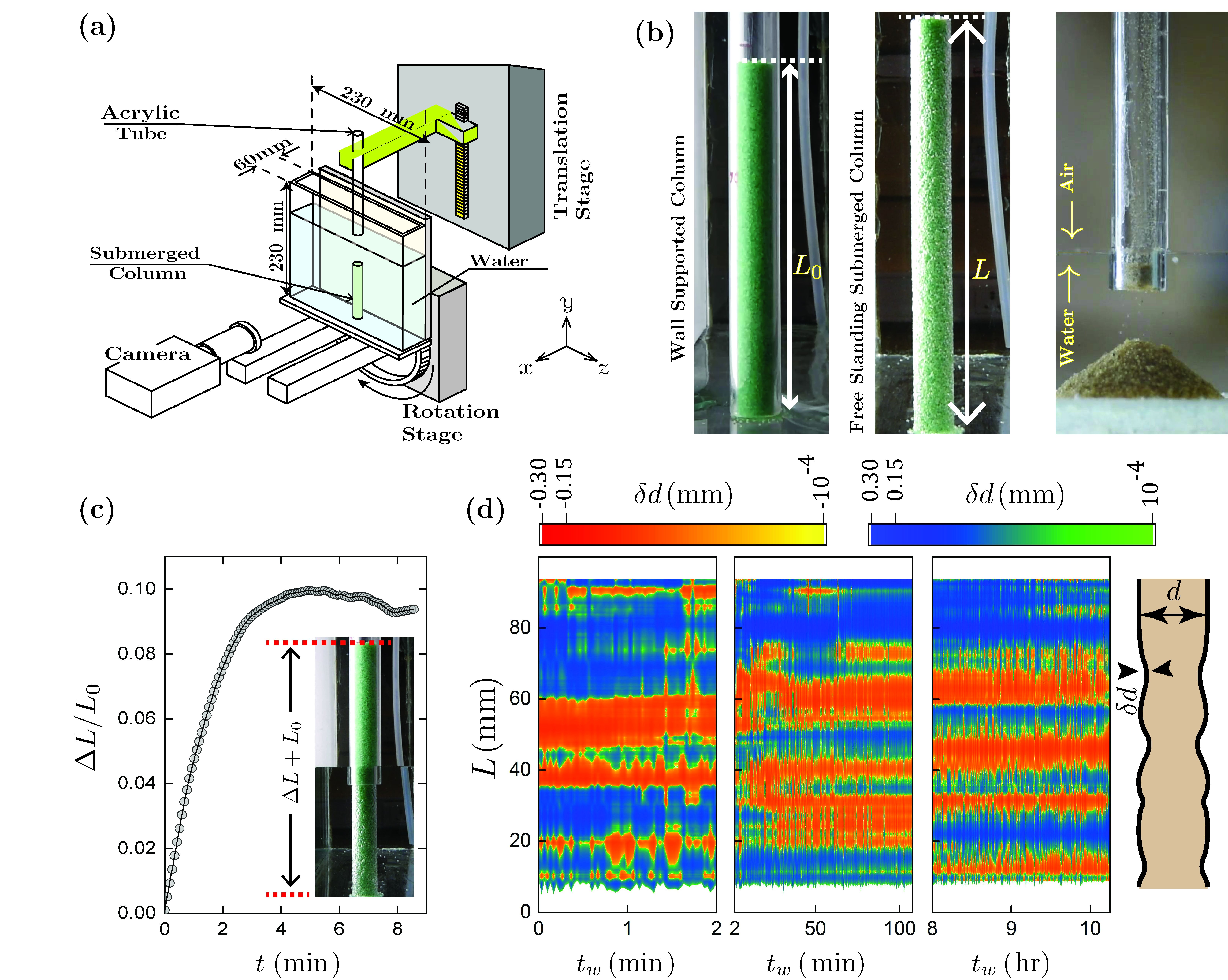
In order to obtain a more comprehensive understanding of the mechanical properties of the system, we choose a relatively simple geometry which is a free-standing submerged cylindrical column built with magic-sand, using the following experimental steps. At First, by selective sieving we obtain grains of different mean sizes , ranging from to . Second, an acrylic tube of inner diameter is made to rest vertically on the flat base of an empty rectangular glass container. The grains are thereafter gently poured into the tube upto a desired height . This forms a wall-supported granular column shown in the left panel of Fig.3(b). The typical packing fraction of the grain assembly is about . Third, and in a key step, the acrylic tube is gradually pulled out while simultaneously filling the glass container with water. Consequently, the hydrostatic pressure partially compensates for the over-pressure due to weight of the grains. This unique protocol prevents grains from clogging
Particles which are in constant physical contact with the wall of the acrylic tube are immobilized by the frictional interactions. As the tube is withdrawn, it drags along particles that are in contact with it This exposes the next layer of particles to water, on which the skin forms. The resulting particle rearrangements reduce the diameter by and increase the height of the column which is now partially submerged in water by . The radial contraction happens within the first few seconds and does not evolve appreciably over time. However, the axial strain keeps increasing in time; see Fig.3(c). As the tube is pulled out, the number of sand grains which are in contact with it decreases. This reduces the extent of particle rearrangements. As a result, the rate of change of decreases with time. The fully submerged column has a length which is about larger than the initial length of the wall-supported column. Hence, the volume fraction of the submerged column is about lower than its value for the wall-supported case. This free-standing submerged column is shown in the middle panel of Fig.3(b). The column is anchored via capillary forces with the hydrophobic substrate at the bottom and is slightly flared close to the anchoring region. Under an identical protocol, hydrophilic beach sand instead slumps to form a canonical sandpile Rondon et al. (2011).
IV Mechanical properties of the column
The submerged column can be thought of as a thin cylindrical shell (made from the skin) containing non cohesive dry grains in its interior. The skin is about a particle diameter thick and it comprises of the sand grains on the outer surface of the column and the pinned three phase contact line. Using a Du-Noüy ring based technique du Noüy (1925) we measure the interfacial energy of the skin to be about . At a microscopic scale this interfacial energy arises from the pinning of the three phase contact line to the defects present on the surface of the grains (see Fig. 2(c) Moulinet et al. (2002). The cohesive coupling stiffness due to this pinning depends on the size of the defect and the typical separation between them. In the limit of strong but sparsely distributed defects, where is the surface energy at the water-air interface de Gennes (1985). Experimentally we observe that polyhedral grains with smooth coverage of hydrophobic coating consistently fail to sustain submerged columns. This suggests that of the multiple scales present in the system, the micron-sized hydrophobic patches present on the surface of the grains are most effective in pinning the contact line.

IV.1 Growth of imperfections of the column
The process of making the column introduces localized geometric imperfections which evolve slowly in time. This is captured by the contour plots of the variation of the column diameter from its mean value along its length over four orders of magnitude in waiting time (Fig.3(d). In Fig.3(d) the blue regions correspond to regions with positive, , modulation and the orange regions correspond to regions with negative, , modulation. The maximum is found to be around , nearly half-a-particle size ; whereas the width of the modulation in along is much larger, approximately 40 particle-lengths. The slow temporal evolution of the column’s deformation is indicative of creep in the presence of strong inter-grain friction, brought about by the competition between the stresses exerted on the skin by the dry grains in the interior Gutiérrez et al. (2015) and the interfacial energy density of the skin. Henceforth, we refer to it as the wrinkling of the skin.
IV.2 An order of magnitude estimate of the elastic constant
In this section we make an order of magnitude estimation of an effective elastic constant for the column. To do so, we apply increasing body forces to the column by gradually tilting the vertical water-filled glass container at a fixed rate; for experimental details see Fig.3(a). Fig.4(a) displays five representative images of the column for increasing values of the tilt angle made by the base of the container with respect to the horizontal. Images corresponding to and capture the process of the column breaking which resembles a mode-I type transverse rupture. As the column breaks from a finite column height , its upper-part traces out a distinct arc, (the inset of Fig.4(b). Here is the failure angle made by the axis of the falling part with a line whose slope is and is the length of the falling part of the column. The column for is about longer than its length for . The variation of failure angle with changes slope at in a semi-log plot (see Fig.4(b). The large slope beyond indicates a rapid toppling of the upper part of the column. We use to mark the onset of mechanical failure. The broken part of the column sinks as a single object.
One cannot build an arbitrarily long and/or thin column. If the gravitational energy of the column exceeds its bending energy , the column will break, here is the effective Young’s Modulus of the column, is its cross sectional area, is moment of inertia of the column and and are the densities of sand and water, respectively. To estimate the maximum height of a column we equate the gravitational energy to the bending energy to obtain,
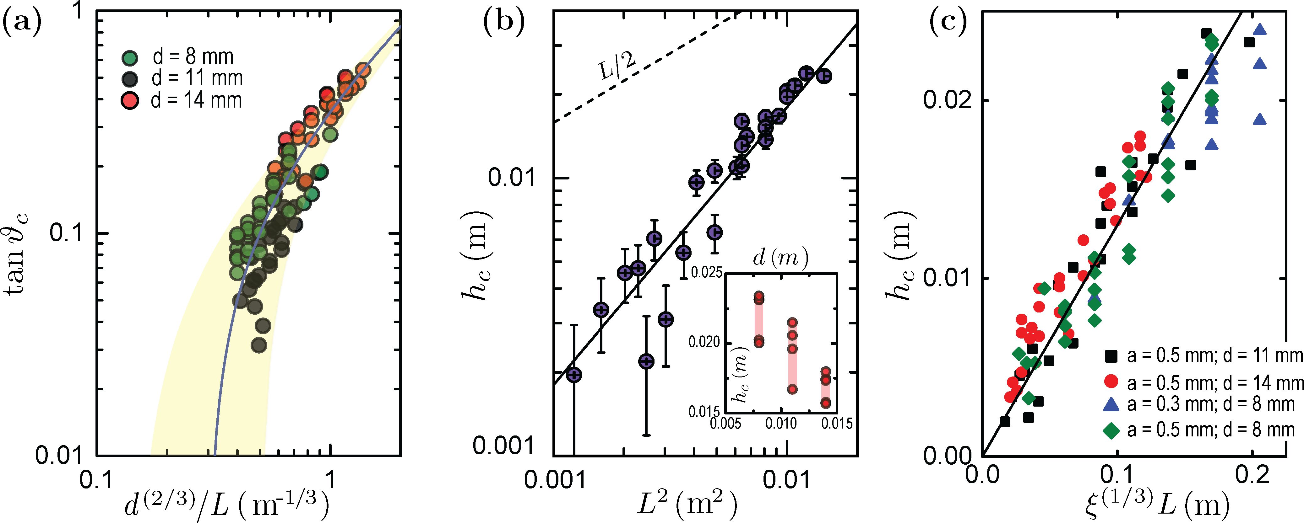
At this maximum height the column breaks in its upright position, i.e., ; this allows us to construct an alternative estimate of from the experimentally observed linear variation where and are fitting parameters; see Fig.5(a). For , we obtain
For , . This estimate of is consistent with experimental observations that stable diameter columns could only be built to the height of . Columns built greater than this height are unstable and fail in their upright position. Equating the above two expressions for we obtain for the submerged column. This is about two orders of magnitude smaller than that observed for wet sand containing water by volume Møller and Bonn (2007).
Heuristic arguments for calculating :
The falling column is visually similar to the well studied problem of a “falling chimney” that breaks mid-air due to tilting Varieschi and Kamiya (2003); Sutton (1936). For the case of a falling chimney the tensile stress at the leading-edge and the compressive stress at the trailing-edge at small tilt angles is maximum at (for tilt angles greater than it is about ), and is usually the point from where the chimney fails Varieschi and Kamiya (2003). Though, one expects a similar spatial variation of the stress for the submerged column, when , we find the following (i) the height at which the column breaks varies quadratically with the column length ; see Fig.5(b) and (ii) decreases with increasing column diameter; see the inset of Fig.5(b).
From a dimensional argument, for values of smaller than , we propose that the height is related to the column length by the following relation where is the ratio of the gravitational and the bending energies Mahadevan and Keller (1996). Since , must vary as , i.e.,
A good agreement of this expression with a large set of experimental data, obtained for different lengths and diameters of the submerged column and for various grain sizes, are shown in Fig.5(c). Here, we have taken the effective Young’s modulus of the column to be a constant, independent of the grain scale, which implies an approximate validity of a continuum mechanical description of the system in this range of deformation.
IV.3 The connection between the wrinkling of the skin and the critical height

The functional dependence of the critical buckling stress on the geometrical parameters for a cylindrical column is different from that of a cylindrical shell. For the column the critical stress is proportional to Timoshenko (1970) whereas for a shell it is proportional to Timoshenko (1970). Here is the thickness of the shell. In the present experiments and , where the shell thickness is of the order of particle diameter . Thus, there are two critical stress values; one that corresponds to the buckling of the shell (skin) and the other that corresponds to the buckling of the column. Since , for increasing values of stress, the buckling of the shell which causes the skin to wrinkle, precedes the failure of the column (assuming that the elastic constant of the entire column is greater than or equal to the elastic constant of the skin alone).
The skin is an integral part of the column and its wrinkling influences the buckling of the column in the following way. The wrinkles on the skin generates geometric imperfections of the column. These imperfections (i) lowers the critical stress at which the system fails Hutchinson and Koiter (1970) and (ii) influence the location from where the system fails. To study the role played by the wrinkles (geometric imperfections of the column) in determining the height from which the column fails we track the curvature of the column along its length for the leading edge till the column breaks up into two pieces.
To calculate , the boundaries of the leading and the trailing edges are passed through a low pass filter that suppresses features smaller than a single grain size Weinhart et al. (2013). These edges are detected using an edge detection algorithm based on Trujillo-Pino et al. (2013). Fig.6 shows the curvature data for the advancing edge.
The contour plot of the curvature clearly shows the existence of bands of high curvature along the length of the column. These bands correspond to the wrinkling of the skin (Fig.3(d). As the column tilts the lowest wrinkle develops into the most prominent imperfection of the column and it acts as a seed from where the failure of the column is initiated.
The critical height from where the column breaks varies quadratically with the length of the column. Since the location of the lowest wrinkle coincides with , it is natural to expect the wavelength associated with the wrinkles to have the same dependence as . However, within the framework of shell buckling, the wavelength of wrinkles is independent of the length of the column Timoshenko (1970). So, a model based solely on buckling produced by static loading is inadequate to describe the experimental scenario.
We speculate that the observed length dependence of is related to the perturbations imparted to the column by the mechanical noise associated with the process of tilting. This gives the loading a certain dynamic character which could in principle facilitate coupling of the various global length-dependent buckling modes to the wrinkling induced localized imperfections of the column Hunt et al. (2003); Abramowicz and Jones (1997). This conjecture needs to be examined in future in greater detail.
IV.4 Opening of the wedge between the falling top and the anchored bottom of the column
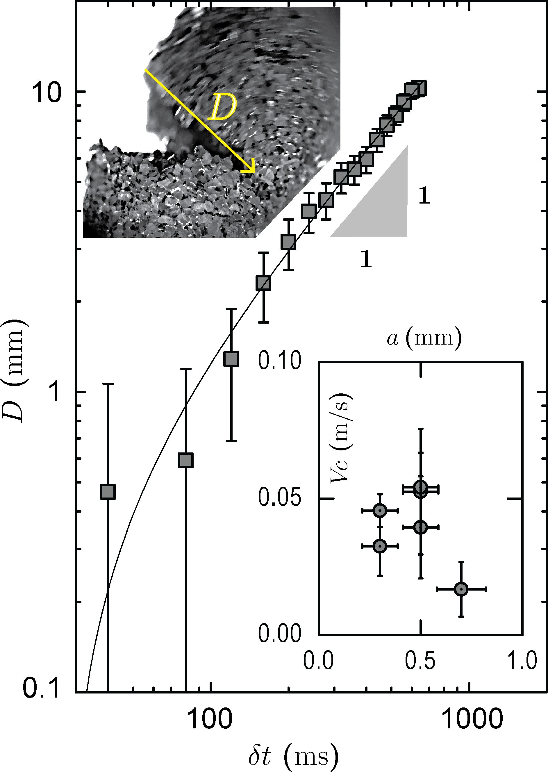
The inset image in Fig.7 displays an instantaneous distance at the apex of the visually identified wedge between the falling top and the anchored bottom parts of the column. This wedge opens up from the trailing (left) edge and progresses towards the advancing (right) edge of the column. The variation of this distance with time is plotted in Fig.7, here the time is measured onwards from the first observable instance of the wedge opening at the left edge between the falling top and the anchored bottom. As can be seen, the wedge advances with an average velocity of .
Neglecting the viscous drag, the time required for a non-anchored column to topple can be obtained by equating the toppling torque acting through the center of mass of the falling part of the column and the rate of change of the angular momentum. This ‘shortest’ falling time is about a second which is the same for the wedge to move across the sample. Accounting for the viscous drag will increase the estimate of the falling time. Unlike conventional solids which break by developing cavities in the bulk, the interior of the submerged column is made of dry grains that cannot support an open gap. The gap can be sustained only if water drains in and generates a confining skin which prevents individual particles from falling into it. Hence, the speed at which the wedge opens sets a lower limit on the tearing speed of the skin. The inset of Fig.7 shows that the particle size influences the speed at which the apex of the visually identified wedge between the falling top and the anchored bottom moves – suggesting that the wedge opening is influenced by tearing of the skin.
IV.5 Effect of stress cycling on the skin
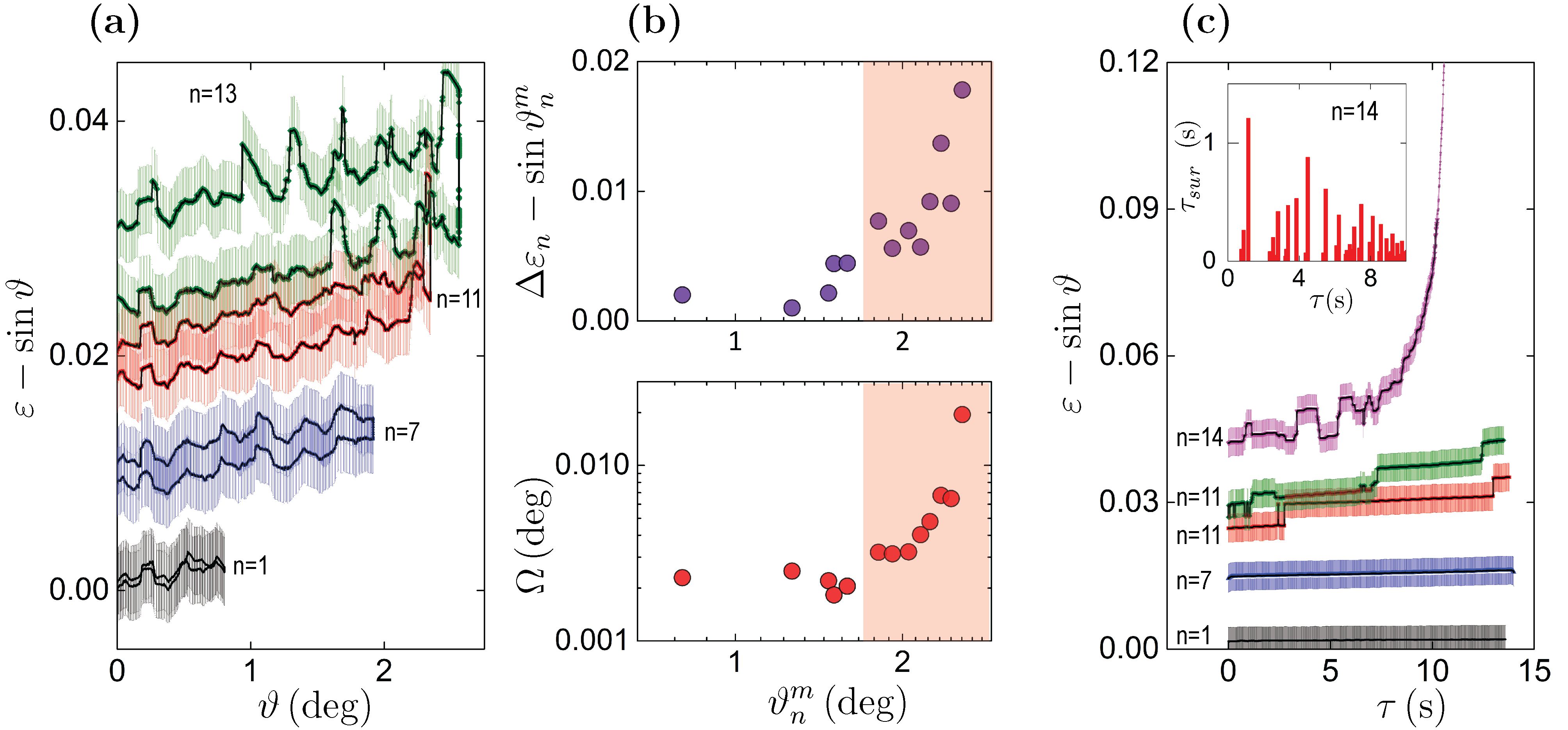
Figure 4 (a) shows that tilting of the column alters the shape of the column. To study the elastic and plastic response of the column, we utilize an incremental stress-cycling protocol; which is the mechanical equivalent of minor hysteresis loop in magnets Barker et al. (1983). Here, the column is recursively stressed such that the minor loops have three branches: (i) an increase branch where the tilt angle increases from 0 to at a fixed rate (ii) a clamp branch where the tilt angle is held constant at for a fixed period of clamping time and (iii) a decrease branch which corresponds to decreasing the tilt angle from to 0, with the same rate as in (i). They are accessed sequentially. For each successive cycle, the maximum tilt angle increases linearly with , where is the numerical index for the cycle. An instantaneous configuration of the submerged column is referred to as , where is the time spent by the system in the clamped state. Fig.8A shows the cyclic variation in the relative displacement as a function of the tilt angle for selective values of 1, 7, 11 and 13 respectively; here and is the distance of the mid-point of the top of the column from the point on the axis (the inset of Fig.4(b). For a first few cycles (), i.e., for smaller values of , the skin deforms in a reversible manner. We limit our statement of the reversibility: it is entirely possible that while the skin may behave in a reversible manner, the dry grains in the interior of the column may not. For larger values of (), the column shows noticeable irreversibility and hence, the hysteresis increases. The parameter is a measure of the strain developed in each cycle while the parameter determines the loop area of each stress cycle; which is a measure of the accumulated hysteresis and dissipation in the system, here . The top and bottom panels of Fig.8B show variation of these two parameters as a function of the maximum tilt angle , respectively.
The following observations can be made from Fig.8 (a) and (b) : (i) the elastic regime of the column extends for beyond which the area of the hysteresis loop begins to increase abruptly. This elastic regime (non-shaded region of Fig. 8(b) can accommodate strains of the order of which is much larger than that observed for dry granular systems. (ii) In the elastic regime, the recursive stress cycling shows smooth variation in with . However, beyond the elastic regime ( or , the shaded region of Fig. 8(b) this variation becomes increasing jagged and clearly shows discrete ‘jumps’ interspersed with smoothly varying sections. These jumps are signatures of mechanical instabilities associated with contact line slippages. They are related to the stress (tilt) induced reduction of the energy barriers associated with the underlying pinning potential which allows the ambient noise (fluctuations) to induce creep like motion of the contact line. Anomalies of elastic constants associated with the break down of linear elastic response generates similar jumps in the flow curves of disordered materials Combe and Roux (2000); Karmakar et al. (2010). (iii) The maximum size of the jump height seen in the quantity is about , i.e., the contact line on an average moves by a particle scale. Further motion of the contact line is possible only by jumping to the next grain which is restricted by the presence of sharp edges at the grain corners Dyson (1988). (iv) The increase in is caused by the cumulative effects of these jumps. These jumps progressively generate local overhangs along the direction of the tilt. This results in the column breaking forward unlike a rigid “falling chimney” which breaks backward Varieschi and Kamiya (2003); Sutton (1936).
The effects of stress assisted creep are best seen in the deformation of the column for the various clamp branches (here is held constant at , see Fig.8(c). The creep increases with increasing tilt angles (forces), e.g., see the branch in Fig.8(c). Even during creep the column evolves in a similarly punctuated stick-slip manner with jumps in the quantity being limited by the value .
As the occurrences of creep increase, the survivaltime of a stationary stick phase decreases; see the inset of Fig.8(c). The jumps themselves are abrupt in the experimental time scale: they occur over a period less than , an order of magnitude shorter than the measured shortest survival time (). The breaking of the column at the macroscopic scale (see Fig.7) is visible only for values of greater than . This region shows a rapid growth of , its initiation is marked by an arrow in Fig.8(c).
V Brittle to ductile to a single particle disintegration: Tuning the failure mode
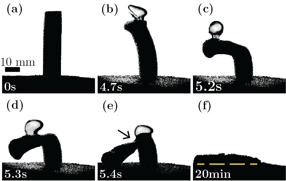
These results imply that the skin, comprising of the air-water-grain interface on the surface layer of grains, is primarily responsible for the mechanical response of the entire system and any modification of the skin will modify the behaviour of the system. One striking modification is shown in Fig.9 where we create a partial vacuum over the water surface, so that the trapped air within the column, one key component of the skin, escapes out from the system as bubbles. The time-lapsed images in Fig.9 (a) (e) demonstrate that here too the failure is initiated by bending at a finite critical height. But, in contrast to the single tear shown above, the column shows large-scale plastic deformations. Its structural integrity is extended for values of greater than by forming a deformed neck, i.e., a narrowing of the column’s diameter, instead of forming a tear or a crack as above. Here, the failure proceeds via this necking instability whose spatial location is marked by an arrow in Fig.9(e). Such large-scale (many-grains wide, in this case) plastic flow and necking instabilities are typical of ductile mode of failure in solids Antolovich and Armstrong (2014), in complete contrast with the brittle failure described above. This change in failure-mode is brought about by the loss of entrapped air causing weaker cohesion in the column that results in conformational changes of a softer skin and finally leads to the ductile failure of the column.
For completeness, we note that a third, and limiting, mode of failure occurs if degassing continues for a long time. In the absence of air, the skin begins to lose its strength (see the lustre-less lump in Fig.1(c). The weak skin eventually fails to sustain the inward hydrostatic pressure and slumps under the slightest mechanical disturbance. The water quickly drains in as the structure disintegrates into a heap of particles, seen in both Fig.1(d) and Fig.9(f); the hydrophobic sand then behaves like its hydrophilic counterpart (right panel of Fig.3(b). The removal of trapped air from the column demonstrates the existence of an underlying dynamical transition via which the failure-mode transforms from being brittle to being ductile, both of which are collective (multi-particles) in nature, and finally to a total disintegration of the skin that represents failure at the single-particle level. This is analogous to dynamical transitions from collective response to single-particle response in a wide class of systems Varshney et al. (2010).
VI Conclusion
This paper provides a detailed study of mechanical properties of underwater granular structures made of hydrophobic sand, where the self-generated cohesive skin on the boundary of the structure encapsulates the dry grains inside it from the surrounding medium water. In our experimental results, three distinct length scales of the system are found. (i) The scale of the hydrophobic patches influences the strength of the pinning of air-water interface on the grain surfaces. Depinning of this interface produces macroscopically observable plastic deformations of the contact lines around (ii) the grain-scale of the sand particles. (iii) At the system scale , the compressive traction forces due to the column’s own weight drives the wrinkling of the skin. The regions of large curvature of the structure are the seeds from where the system-sized failure modes nucleate. By partially removing the trapped air from this structure, we also see that the collective failure can be tuned from brittle to ductile. A more complete removal of air causes the skin to crumble completely into individual non-cohesive grains inside water. These experimental findings imply the existence of a tunable dynamical transition between a collective and an individual (single-grain) mode of failure in this system. We expect that these new results will help in engineering the granular encapsulation with desired material-properties in a variety of applications and, at the same time, it provides a deeper insight of the multi-scale mechanics, generic to granular materials.
We acknowledge discussions with A. Ghatak, M. Tirumkudulu, I. Sharma and M. Bandi. We especially thank the anonymous referees for many critical and valuable comments on the manuscript.
References
- Amarouchene et al. (2008) Y. Amarouchene, J.-F. Boudet, and H. Kellay, Physical Review Letters 100, 218001 (2008).
- Cheng et al. (2007) X. Cheng, G. Varas, D. Citron, H. M. Jaeger, and S. R. Nagel, Physical Review Letters 99, 188001 (2007).
- Forterre and Pouliquen (2008) Y. Forterre and O. Pouliquen, Annual Review of Fluid Mechanics 40, 1 (2008).
- Cheng et al. (2008) X. Cheng, L. Xu, A. Patterson, H. M. Jaeger, and S. R. Nagel, Nature Physics 4, 234 (2008).
- de Gennes (1999) P. G. deGennes, Reviews of Modern Physics 71, S374 (1999).
- Strauch and Herminghaus (2012) S. Strauch and S. Herminghaus, Soft Matter 8, 8271 (2012).
- Mitarai and Nori (2006) N. Mitarai and F. Nori, Advances in Physics 55, 1 (2006).
- Soulié et al. (2006) F. Soulié, F. Cherblanc, M. El Youssoufi, and C. Saix, International Journal for Numerical and Analytical Methods in Geomechanics 30, 213 (2006).
- Herminghaus (2005) S. Herminghaus, Advances in Physics 54, 221 (2005).
- Gutiérrez et al. (2015) G. Gutiérrez, C. Colonnello, P. Boltenhagen, J. R. Darias, R. Peralta-Fabi, F. Brau, and E. Clément, Phys. Rev. Lett. 114, 018001 (2015).
- Py et al. (2007) C. Py, P. Reverdy, L. Doppler, J. Bico, B. Roman, and C. N. Baroud, Physical Review Letters 98, 156103 (2007).
- Paulsen et al. (2015) J. D. Paulsen, V. Démery, C. D. Santangelo, T. P. Russell, B. Davidovitch, and N. Menon, Nature materials 14, 1206 (2015).
- Aussillous and Quéré (2001) P. Aussillous and D. Quéré, Nature 411, 924 (2001).
- Binks and Lumsdon (2001) B. P. Binks and S. O. Lumsdon, Langmuir 17, 4540 (2001).
- Dinsmore et al. (2002) A. D. Dinsmore, M. F. Hsu, M. G. Nikolaides, M. Marquez, A. R. Bausch, and D. A. Weitz, Science 298, 1006 (2002).
- Dickey et al. (2008) M. D. Dickey, R. C. Chiechi, R. J. Larsen, E. A. Weiss, D. A. Weitz, and G. M. Whitesides, Advanced Functional Materials 18, 1097 (2008).
- Aussillous and Quéré (2006) P. Aussillous and D. Quéré, in Proceedings of the Royal Society of London A: Mathematical, Physical and Engineering Sciences, Vol. 462 (The Royal Society, 2006) pp. 973–999.
- Abkarian et al. (2013) M. Abkarian, S. Protière, J. M. Aristoff, and H. A. Stone, Nature communications 4, 1895 (2013).
- Subramaniam et al. (2006) A. B. Subramaniam, M. Abkarian, L. Mahadevan, and H. A. Stone, Langmuir 22, 10204 (2006).
- Pakpour et al. (2012) M. Pakpour, M. Habibi, P. Moller, and D. Bonn, Scientific Reports 2, 5498 (2012).
- Hornbaker et al. (1997) D. Hornbaker, R. Albert, I. Albert, A.-L. Barabási, and P. Schiffer, Nature 387, 765 (1997).
- Saleh and Guigon (2007) K. Saleh and P. Guigon, in Granulation, Handbook of Powder Technology, Vol. 11, edited by M. H. A.D. Salman and J. Seville (Elsevier Science B.V., 2007) pp. 323 – 375.
- Andreotti et al. (2013) B. Andreotti, Y. Forterre, and O. Pouliquen, Granular media: between fluid and solid (Cambridge University Press, 2013).
- Moulinet et al. (2002) S. Moulinet, C. Guthmann, and E. Rolley, The European Physical Journal E 8, 437 (2002).
- Quéré (2005) D. Quéré, Reports on Progress in Physics 68, 2495 (2005).
- Quéré et al. (2003) D. Quéré, A. Lafuma, and J. Bico, Nanotechnology 14, 1109 (2003).
- Miguel and Rubi (2006) C. Miguel and M. Rubi, Jamming, yielding, and irreversible deformation in condensed matter, Vol. 688 (Springer, 2006).
- Varshney et al. (2012) A. Varshney, A. Sane, S. Ghosh, and S. Bhattacharya, Physical Review E 86, 031402 (2012).
- Davis (1955) G. E. Davis, Journal of the Optical Society of America 45, 572 (1955).
- Marston (1979) P. L. Marston, Journal of the Optical Society of America 69, 1205 (1979).
- Rondon et al. (2011) L. Rondon, O. Pouliquen, and P. Aussillous, Physics of Fluids 23, 073301 (2011).
- du Noüy (1925) P. L. du Noüy, The Journal of general physiology 7, 625 (1925).
- de Gennes (1985) P. G. de Gennes, Rev. Mod. Phys. 57, 827 (1985).
- Varieschi and Kamiya (2003) G. Varieschi and K. Kamiya, American Journal of Physics 71, 1025 (2003).
- Sutton (1936) R. M. Sutton, Science 84, 246 (1936).
- Møller and Bonn (2007) P. C. Møller and D. Bonn, Europhysics Letters 80, 38002 (2007).
- Mahadevan and Keller (1996) L. Mahadevan and J. B. Keller, Proceedings of the Royal Society of London A: Mathematical, Physical and Engineering Sciences, 452, 1679 (1996).
- Timoshenko (1970) S. Timoshenko, Theory of Elastic Stability 2e (Tata McGraw-Hill Education, 1970).
- Hutchinson and Koiter (1970) J. Hutchinson and W. Koiter, Appl. Mech. Rev 23, 1353 (1970).
- Weinhart et al. (2013) T. Weinhart, R. Hartkamp, A. R. Thornton, and S. Luding, Physics of Fluids 25, 070605 (2013).
- Trujillo-Pino et al. (2013) A. Trujillo-Pino, K. Krissian, M. Alemán-Flores, and D. Santana-Cedrés, Image and Vision Computing 31, 72 (2013).
- Hunt et al. (2003) G. Hunt, G. J. Lord, and M. A. Peletier, Discrete and Continuous Dynamical Systems Series B 3, 505 (2003).
- Abramowicz and Jones (1997) W. Abramowicz and N. Jones, International Journal of Impact Engineering 19, 415 (1997).
- Barker et al. (1983) J. Barker, D. Schreiber, B. Huth, and D. Everett, in Proceedings of the Royal Society of London A: Mathematical, Physical and Engineering Sciences, Vol. 386 (The Royal Society, 1983) pp. 251–261.
- Combe and Roux (2000) G. Combe and J.-N. Roux, Physical Review Letters 85, 3628 (2000).
- Karmakar et al. (2010) S. Karmakar, E. Lerner, and I. Procaccia, Physical Review E 82, 055103 (2010).
- Dyson (1988) D. Dyson, Physics of Fluids (1958-1988) 31, 229 (1988).
- Antolovich and Armstrong (2014) S. D. Antolovich and R. W. Armstrong, Progress in Materials Science 59, 1 (2014).
- Varshney et al. (2010) A. Varshney, P. Sharma, A. Sane, S. Ghosh, and S. Bhattacharya, Phys. Rev. Lett. 105, 154301 (2010).