LASeR: Lightweight Authentication and Secured Routing for NDN IoT in Smart Cities
Abstract
Recent literature suggests that the Internet of Things (IoT) scales much better in an Information-Centric Networking (ICN) model instead of the current host-centric Internet Protocol (IP) model. In particular, the Named Data Networking (NDN) project (one of the ICN architecture flavors) offers features exploitable by IoT applications, such as stateful forwarding, in-network caching, and built-in assurance of data provenance. Though NDN-based IoT frameworks have been proposed, none have adequately and holistically addressed concerns related to secure onboarding and routing. Additionally, emerging IoT applications such as smart cities require high scalability and thus pose new challenges to NDN routing. Therefore, in this work, we propose and evaluate a novel, scalable framework for lightweight authentication and hierarchical routing in the NDN IoT (NDNoT). Our ns-3 based simulation analyses demonstrate that our framework is scalable and efficient. It supports deployment densities as high as 40,000 nodes/km2 with an average onboarding convergence time of around 250 seconds and overhead of less than 20 KiB per node. This demonstrates its efficacy for emerging large-scale IoT applications such as smart cities.
Keywords: ICN, IoT, secure onboarding, secure routing, networking, smart cities.
I Introduction
The new emerging concept of smart cities applies concepts from the Internet of Things (IoT) to the management of diverse municipal infrastructure and assets [1]. Smart cities will involve large numbers of IoT devices installed in a range of settings from individual homes to critical infrastructure, potentially in a very dense deployment. As a result, their feasibility will require advances in efficiency and scalability of IoT communications. Additionally, smart cities will require strong guarantees of security: networked devices will handle large volumes of sensitive information and control valuable assets such as utility infrastructure, thus widening the attack surface for potential compromise. Thus, strong end-to-end security and privacy mechanisms between smart devices and the cloud are imperative.
Recent literature suggests that Information-Centric Networking (ICN) is a more appropriate approach than Internet Protocol (IP) for IoT [2]. Named Data Networking (NDN) [3], in particular, is a strong architecture for creating scalable and efficient smart city networks, by employing features such as stateful forwarding and in-network caching. In addition, it offers security benefits such as enforced provenance through mandatory network-layer signatures.
Several ICN-based IoT deployments have been announced in the literature, however no holistic NDN of Things (NDNoT) architecture and protocol suite has yet been proposed. In particular, existing literature tends to neglect concerns related to secure routing and onboarding, two of the most difficult problems in IoT. Works that do address routing or onboarding do so separately, neglecting the fact that they are closely coupled. As a result, the proposed disjoint schemes are either incompatible or inefficient when combined. Therefore, we propose in this paper a scalable and secure framework addressing both onboarding and routing in the NDNoT.
The scalability of an IoT deployment is adversely affected by the low computational and memory capacities of IoT devices, as well as the characteristics of the low power lossy networks (LLNs) they use to communicate. Thus, we employ a hierarchical network structure, a design which has been recommended to achieve scalability in IoT [4]. Such an architecture allows us to offload the burden of routing onto a few less-constrained “anchor” nodes, while other devices need only form destination-oriented trees.
In our framework, secure onboarding is made a prerequisite to routing, in order to help protect the network against routing attacks such as blackholes [5]. Each node in the network is authenticated prior to commencing routing, and in turn a node also authenticates the network it is joining. Since asymmetric cryptography is typically infeasible on IoT devices, we use symmetric cryptography. Our onboarding protocol is based on pre-shared keys between each node and a designated authentication manager in the infrastructure.
We have combined our approaches to routing and onboarding into a single holistic framework for Lightweight Authentication & Secured Routing (LASeR). The combined authentication and onboarding processes are very lightweight, requiring only three round trips and few cryptographic operations.
In summary, the contributions of our work are: (1) We analyze the current state-of-the-art of routing and authentication in the NDNoT; (2) We propose LASeR, a holistic framework for efficient and secure onboarding and routing in NDN; and (3) We demonstrate LASeR’s effectiveness and efficiency through analyses conducted in ndnSIM, the NDN module for ns-3.
The remainder of this paper is organized as follows: Section II reviews prior work on NDN and IoT; Section III presents our model for the IoT network and reviews the primitives employed by NDN; Section IV describes the cryptographic materials and operations underlying LASeR’s authentication mechanism; Section V presents the protocols employed for onboarding and routing; Section VI offers a simulation-based validation of LASeR’s effectiveness; and finally, Section VII concludes the paper and gives an overview of our planned future work.
II Related Work
Benefits and challenges related to the ICN-based IoT have been previously discussed in the literature [6, 7, 2], and several architectures have been proposed for both general IoT [2] and specific applications [8, 9, 10]. However, the majority of these designs focus on service discovery, data delivery, and similar application-centric concerns rather than the initial network bootstrapping or route discovery procedures and their security.
Though most of the aforementioned works do not suggest novel routing protocols for IoT, [2] recognized the routing-related challenges imposed by device constraints in the IoT and proposed a new opportunistic-reactive routing protocol. Under this model, forwarding tables are populated after observing the origins of downstream packets; a flooding-based approach is used as a fallback when no proper route is available. A similar approach was previously outlined in [11].
Other approaches to ad-hoc routing in NDN were reviewed in [12]; the authors identified two broad classes of routing protocols: provider-blind and provider-aware. The provider-blind schemes solely employ controlled flooding to forward requests, while provider-aware schemes add a reactive mechanism like that in the two designs mentioned above. All these routing protocols employ reactive designs; however, we choose a proactive approach like that of the IPv6 Routing Protocol for Low-Power and Lossy Networks (RPL) [13], which is currently favored for the IP-based IoT.
Bootstrapping and onboarding for the ICN-based IoT have only recently been given serious consideration. Previous architectures such as [10] relied on the asymmetric authentication mechanisms used throughout the NDN stack, however [14] quantified the time and energy overheads of such schemes on constrained devices and ultimately concluded that their cost is too high. As a result, two designs based on symmetric cryptography were proposed in [15]: a basic implementation of the authenticated key exchange protocol (AKEP2) [16] over ICN, and an improved version which increases its efficiency.
Though [15] efficiently addresses the initial authentication and key-distribution challenges for IoT, it does so without regard to the needs of a routing protocol. As a result, to employ it in conjunction with a separate routing framework would impose additional overhead; the two steps of authentication and routing will occur serially, increasing overhead in the network and overall onboarding latency. In light of this, we propose LASeR, wherein elements of authentication and routing can occur simultaneously to reduce their overall cost.
III System and Threat Models and Assumptions
In this section, we present the system, network, and threat models and assumptions. For better understanding of our models and assumptions, we start with an overview of NDN.
III-A Overview of NDN
The “thin waist” of the Named Data Networking (NDN) stack, as the name implies, is Named Data. In the NDN model, each chunk of data (typically referred to as a content object) has a unique Name, similar to a Uniform Resource Identifier (URI); the content associated with each Name is typically considered to be immutable. To retrieve a particular content object, a requester sends an Interest packet into the network. At a minimum, the Interest contains the Name of the desired content object; it can also contain a signature to verify the requester’s identity. The network then retrieves the appropriate content object and delivers it to the requester as a Data packet. The Data contains, at a minimum, its Name, the actual content payload, and its publisher’s signature. The requester can then verify the signature to ascertain the content object’s authenticity. Both Interest and Data signatures typically (but optionally) include a KeyLocator field, which contains the Name of the key used for the signature.
Each router in NDN maintains three data structures: a Pending Interest Table (PIT), a Forwarding Information Base (FIB), and a Content Store (CS). The forwarding procedures for both Interests and Data are based around these tables. Upon receiving an Interest, a router first checks its CS for a match; the CS essentially serves as a cache of Data, indexed by Name. If a match is found in the CS, the Data is served and the request is considered satisfied. If no match is found in the CS, the router then checks its PIT, which indicates whether a previous Interest for the same Name has been forwarded but not yet satisfied.
If a PIT entry exists, the router need not forward the Interest again; instead, it adds the identifier of the incoming interface (Face, in the NDN nomenclature) to that PIT entry. If no PIT entry is found, the router consults its FIB (essentially a forwarding table) and employs a configurable forwarding strategy to identify the correct Face on which to forward the Interest. The router then adds a new PIT entry indicate that the Interest was forwarded.
Data packets are essentially forwarded following the reverse path as indicated by matching PIT entries. That is, a router receiving a Data checks its PIT to determine the correct Face(s) on which to forward the Data. Once the Data is forwarded, the PIT entry is cleared. The Data may then be added to the CS and used to satisfy future requests, depending on the policy employed for cache admission and eviction.
Note that the configurability of the forwarding strategy is an important feature for the application of NDN in IoT. A different strategy can be employed for each Interest depending on its Name prefix, allowing, for example, enhanced Quality of Service (QoS) depending on the nature of the request. In LASeR, we employ a custom strategy to facilitate our hierarchical network design; more details on this strategy are given in Section V-E3.
III-B System Model and Assumptions
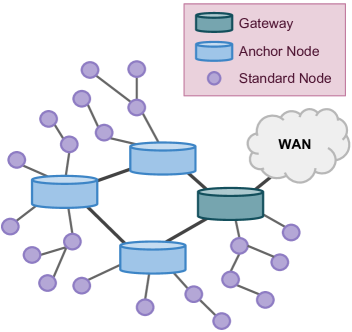
We model the NDNoT as consisting of islands, which exist at the edge of the greater Internet. The protocols employed within the island need not be influenced by those used in the wide-area network (WAN); therefore, this model is suitable for a local clean-slate deployment of NDN in smart cities prior to wide adoption.
We distinguish between three types of nodes within each island: gateways, anchor nodes (ANs), and standard nodes (SNs). We assume that SNs have small memory, computation, and energy capacities, and employ LLN radios; on the other hand, gateways and ANs are essentially unconstrained. The connections between these entities are visualized in Fig. 1. Gateways serve as edge routers between the island and the WAN, and the ANs are a superset of the gateways and form a backbone or core for the island. Standard nodes wirelessly peer with ANs and use them as sinks to facilitate communication, thus creating trees, or clusters, of constituent SNs around each AN.
We assume each SN is assigned a flat identifier (ID), which could either be derived from its media access control (MAC) address or be chosen arbitrarily. For scalability, we will use these IDs to perform routing and forwarding. Nodes can also advertise arbitrary, application-specific Name prefixes; other requesters would then resolve these Names into IDs for the purpose of routing. Namespace creation and management is an NDN- and application-specific decision. This is outside the scope of this work.
In addition to network entities named above, we assume that there is a service capable of managing the authentication and registration of nodes in the network. We will refer to this entity as the Island Manager (IM); it may exist either in the cloud, within some particular node, or even as a synchronized database shared between anchors. We assume that the IM and ANs are synchronized to perform secure communication and routing. We do not discuss mechanisms to achieve this, however it is easy to design and implement. The placement of the IM is an implementation detail which should be made with consideration to the specific needs of a particular deployment. The IM will be responsible for node authentication, and will also serve Name-to-ID resolution requests to support hierarchical routing.
III-C Threat Model and Assumptions
We assume that all the devices in the network are capable of performing symmetric key cryptography, such as advanced encryption standard (AES), and message authentication using keyed-hashed functions, such as hashed-MAC. As is standard, we assume that the encryption algorithms and the MAC functions cannot be compromised. In our system, there can be both inside and outside attackers. An outside attacker is not part of the network. It can passively capture data transmissions in the network to perform traffic analysis and also replay captured packets. It can also be an active attacker attempting to masquerade as a legitimate node, and can try to inject false data into the network. An inside attacker is a node that is already on-boarded into the network, it can also inject false data in the network. The false data can include fake route advertisements, enabling sinkhole or blackhole attacks. A compromised or colluding node’s keying materials can be extracted and used by an adversary, not part of the system, to impersonate as a legitimate node. This is termed sybil attack; the compromised adversary can operate as a legitimate node in the network. Denial of service and channel jamming can also be threats in our system.
IV Cryptographic Materials and Primitives
IV-A Overview
The key hierarchy of LASeR, visualized in Fig. 2, is inspired by that of the Pre-Shared Key Extensible Authentication Protocol (EAP-PSK) [17]. A session between an SN and an IM is identified by the respective IDs of the two parties as well as two nonces (one chosen by each). The SN and IM initially share a pre-shared key (PSK), from which two long-lived keys are derived (one for key derivation, one for authentication). With the exchange of nonces and establishment of a session, two additional transient keys are established (one for encryption, one for authentication). These transient keys can be intermittently refreshed simply by exchanging new nonces.
IV-B Permanent Materials
Each SN is required to store at least two permanent pieces of information: its ID (IDSN) and its PSK (PINSN), which could be installed at the time of manufacture. The IM is required to permanently store only its own ID (IDIM). The IDs may be arbitrary, and the PSK should be random.
IV-C Long-Lived Keys
As in EAP-PSK, we use a PSK (in this case, PINSN) in order to derive two long-lived keys: the Authentication Key (AKSN), and the Key-Derivation Key (KDKSN). For ease of implementation, we use a password-based key derivation function (PBKDF2) [18], rather than the modified counter mode block cipher used by EAP-PSK, to derive these keys from the PSK. Following the construction in EAP-PSK, we configure PBKDF2 with the following options: PINSN as the password, IDSN as the salt, and an output length of 256 bits. The first 128 bits of output shall be used as AKSN, and the last 128 bits as KDKSN. We use HMAC-SHA256 as the pseudorandom function behind PBKDF2, due to its wide use and ease of implementation.
The SN may optionally pre-generate and cache both AKSN and KDKSN permanently, though it is not required to. The IM cannot generate these keys until binding time, as it may not have prior knowledge of IDSN. To enable use of NDN’s in-stack authentication features, AKSN should be registered on both nodes as /keys/<IDSN>/AK, and KDKSN registered as /keys/<IDSN>/KDK.
IV-D Transient Keys
To enhance security, the static keys derived directly from the PSK are not used to transmit application data, but only to bootstrap the authentication process. As in EAP-PSK, two nonce-based ephemeral keys will be derived from the key-derivation key. In particular, KDKSN is used to derive two transient keys: a Transient Authentication Key (TAKSN), and a Transient Encryption Key (TEKSN). Again, we use PBKDF2 with HMAC-SHA256 to derive 256 bits of keying material. The key KDKSN is used as the password, and a pair of nonces (RSN and RIM) established during the handshake is used as the salt (details in Section V). These keys are also registered within the local NFD for ease of use: TAKSN is registered as /keys/<IDSN>/<RSN>/<RIM>/TAK, and TEKSN as /keys/<IDSN>/<RSN>/<RIM>/TEK.
IV-E Secure Channel
Once TAKSN and TEKSN are derived, a secure channel can be established. Messages are encrypted with AES128-CBC under TEKSN, while TAKSN is used for HMAC-SHA256 signing. These keys are used to deliver an additional symmetric key to used for route advertisement, namely the Routing Authentication Key (RAK).
In the following sections, we use the notation [ ... ]K to indicate that a message is signed under the key K, and { ... }K to indicate that a message is encrypted under K.
V The LASeR Protocol
V-A Overview
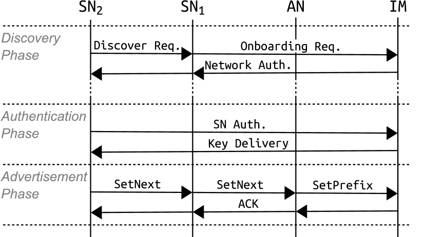
Onboarding and routing using LASeR occurs in three steps, depicted in Fig. 3: (1) network discovery and authentication, (2) SN authentication and key delivery, and (3) path advertisement. In the first phase, an SN discovers an already-onboarded neighbor, who then asks the IM for the information necessary to authenticate the network to the new SN. In the second phase, the SN authenticates itself to the IM and acquires the keys necessary to advertise a route. The final phase consists solely of the SN advertising its route; the route is then propagated hop-by-hop toward the anchor using SetNext messages. The anchor then notifies the IM of the SN’s registration using a SetPrefix message. The full process can be performed in as little as three round trips between a joining SN and the IM.
The resulting routes from SNs to ANs are similar to those which would be obtained by a scheme based on destination-oriented directed acyclic graphs (DODAGs) such as RPL [13]. However, each node chooses only one upstream path in LASeR and therefore the result is a forest of trees, each rooted at an AN (equivalent to sinks in RPL nomenclature). Routing between anchors and gateways is assumed to be handled by other means, e.g. a link-state protocol, and is beyond the scope of this work.
V-B Network Discovery and Authentication
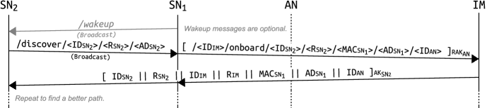
The first stage of LASeR is network discovery and authentication; that is, an SN discovers a path and verifies the legitimacy of the network it is connecting to. It involves three network entities: the node joining the island (SN2), its neighbor (SN1), and the island manager (IM). The discovery process may begin either when SN2 first comes online, or at a later time when it receives a wakeup beacon (a notification from a newly-onboarded neighbor that a path to an AN is now available). The complete discovery protocol is presented in Fig. 4.
The first transmission in this phase is a Discovery Request sent by SN2, which constitutes a request to join an island. This transmission is an Interest under the /discover/ prefix, which is assumed to be broadcast-forwarded in order for SN2 to identify an immediate neighbor. The Interest should have a relatively long PIT lifetime (likely on the order of minutes), as it may require human input at the IM (to enter PINSN2, if it is not pre-shared) before a Data can be sent in response.
This initial Interest sent by SN2 contains its ID (IDSN2), a self-generated nonce (RSN2), and its current hop-distance from an anchor (ADSN2, initially ); the complete name is /discover/<IDSN2>/<RSN2>/<ADSN2>. Any neighbor (SN1) which receives this message, is fewer than ADSN2 hops from an anchor, and wishes to serve as a relay for SN2 shall relay it to its AN along with its own MAC (MACSN1), its hop-count distance from an anchor (ADSN1), and the ID of that anchor (IDAN). This message, an Onboarding Request, essentially represents SN1’s assent to providing a route towards AN for SN2. To this end, SN1 constructs a new Interest for /<IDIM>/onboard /<IDSN2>/<RSN2>/<MACSN1>/<ADSN1>/<IDAN> and signs it under RAKAN (which is shared by all successfully-onboarded nodes under the AN, as well as by the IM).
Upon receiving this Interest, the IM derives AKSN2 and KDKSN2 according to the procedure outlined in Section IV-C. It generates its nonce RIM and replies with a Network Authentication (NA) message, which is a Data containing IDSN2, RSN2, IDIM, RIM, MACSN1, ADSN1, and IDAN. The Data is signed under AKSN2. This Data authenticates IM to SN2, informs it of its next-hop neighbor (SN1), its distance from an anchor (ADSN1 + 1), and its anchor (AN). Because SN1 changed the Interest name in-flight, it must perform the corresponding reverse mapping in order to deliver the message to SN2; i.e., the application layer changes the Data’s Name from that in the Onboarding Request to that in the original Discovery Request.
After obtaining this Data, SN2 may send a new discover Interest in order to attempt to locate a shorter path to an anchor (in the context of our example, a different node would then take on the role of SN1). To do so, it sends the same Interest as previously but with a new nonce and an updated AD field. This process may be iterated as many times as desired, or until SN2 no longer receives a useful response.
When SN2 is content with its path, it notes its next hop toward the anchor as IDSN1 and its anchor as IDAN, then proceeds to phase two as follows.
V-C SN Authentication and Key Delivery
After completing the first phase, SN2 trusts its island (via its trust for the IM) and is capable of forwarding Interests to any entity within. However, the island does not yet trust SN2.
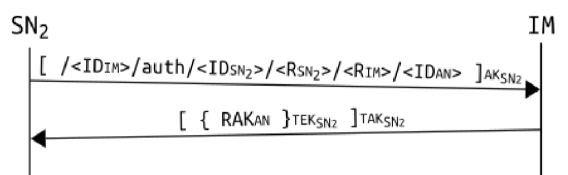
In order to establish this trust, SN2 begins the second phase, which is illustrated in Fig. 5. This phase begins with SN2 sending its SN Authentication (SA), a signed Interest to IM containing the previously exchanged nonces, RSN2 and RIM, as well as IDSN2, IDAN, and IDIM. This Interest is to be routed using the next-hop information ascertained in the first phase. The IM, upon receiving the Interest, verifies the signature and content and produces a Data packet containing the anchor-specific RAKAN (shared secrets between IM and ANs are always synchronized). The key is encrypted under TEKSN2 and signed under TAKSN2. At this point, SN2 is authenticated and can move into the third phase to advertise its path.
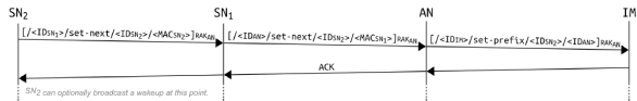
V-D Path Advertisement
All information necessary for SN2 to route Interests to other nodes in the island was acquired in the first phase; however, no node is yet able to route interests to SN2. In order for Interests to be delivered to SN2, each node on the path between SN2 and AN must know the next hop toward SN2. To update this routing state, SN2 sends a notification called a SetNext message upstream, signed under RAKAN.
To keep track of downstream nodes, each SN and AN maintains a Downstream Forwarding Base (DFB), which maps a node ID to the next-hop MAC address. The strategy layer of each node uses the DFB and the FIB to make forwarding decisions regarding Interests with destinations in the same AN’s cluster.
To inform the next-hop node of its location, SN2 creates the SetNext Interest with its neighbor’s prefix (IDSN1) and the command /set-next, followed by its own ID (IDSN2) and the MAC address of SN1’s next-hop toward it (in this case, MACSN2). This Interest is signed with RAKAN. SN1 receives this interest, updates its DFB, then constructs a similar Interest informing the next upstream node that it is the next-hop to reach SN2. This process, illustrated in Fig. 6, continues until the packet reaches the AN.
When the AN receives this Interest, it updates its DFB and sends a SetPrefix notification to the IM to record that it serves as SN2’s anchor. This allows the IM to serve name resolution requests for SN2. The IM responds with a simple ACK message, which should be forwarded hop-by-hop to satisfy the PIT entries for these Interests, and ultimately notify SN2 that it has been successfully onboarded.
Upon receiving the ACK, SN2 may send a wakeup Interest (Name /wakeup) to notify nearby nodes that it has been onboarded and can now facilitate their onboarding. This procedure can help expedite the initial onboarding process for an island.
V-E Additional Considerations
The above protocols accomplish secure onboarding and routing. In what follows, we will discuss some additional maintenance procedures in LASeR, such as key refresh, prefix resolution, and routing between ANs.
V-E1 Key Refresh
Both the SN’s session keys and the AN’s RAK may need to be periodically refreshed in order to maintain the security of the island. When the SN wants to change keys, it can either restart from the discovery process, or contact the IM directly to exchange new nonces. In the latter case, the same authentication procedure applies. In order to refresh RAKAN, the IM should generate the new key and send [{<RAKAN>}TEKi]TAKi to each node in the AN’s cluster, as well as the AN itself.
V-E2 Prefix Resolution
To enable hierarchical forwarding based on ANs, after committing to a path, an SN assumes a new name-prefix rooted under its AN. This prefix is communicated to the IM at the end of the path-advertisement protocol (Section V-D). The IM stores a mapping of IDs to prefixes, and can respond to Interests querying for the prefixes of registered nodes (e.g., respond to an Interest /<IDIM>/get-prefix/<IDSN>). Similarly, the SNs and the ANs need to be able to remap Interests onto the appropriate prefixes. Additional arbitrary Name prefixes that a node wishes to serve should also be communicated to the IM. The IM also resolves requests for these arbitrary Names into routable Names, constructed from the corresponding IDs and AN prefixes. The processes for name registration and resolution are quite simple and can be done in various ways. Due to space constraints this discussion is omitted in this paper.
V-E3 Routing Within and Between Clusters
In LASeR, anchors obtain routes to each other out-of-band, for example using a link-state algorithm such as NLSR [19]. By virtue of hierarchical naming and prefix-based forwarding, anchors need not advertise the constituent nodes in their clusters, only their own prefixes. We assume that the gateway is also a member of this link-state session, and therefore any standard node can reach the gateway just as easily as it can reach an anchor.
In order to reach a node within the same cluster, forwarding nodes use their DFBs. However, each node only has DFB entries for those nodes that rely on it for a path to the anchor. Therefore, in our framework nodes route toward the anchor by default if the DFB lookup fails. As a result, packets between nodes in the same cluster (e.g., machine-to-machine flows) climb the tree toward the AN until the first common ancestor is reached; the packet is then forwarded down the tree to the destination.
To reach a node in another cluster, the IM must first be queried to obtain the node’s prefix, as mentioned in Section V-E2 (Prefix Resolution). This operation can be made transparent to applications by performing it in the strategy layer, and the prefix returned by the IM can be cached to reduce latency for future requests.
V-F Security Analyses
The goal of LASeR is to secure routing in a smart city IoT network. Therefore, we focus on analyzing concerns related to the authenticity and provenance of obtained routes. We will also remark on privacy concerns where applicable.
The authentication and key exchange procedures in LASeR are effectively equivalent to those of EAP-PSK and AKEP2, which have been proven in literature to be secure. However, the use of a shared RAK for securing routing messages between nodes in a cluster is a potential vulnerability. Though the RAK is always transmitted in an encrypted form, its compromise (through brute force or node takeover) would allow an attacker to publish fake routes on behalf of any node in the compromised cluster.
The result of such an attack would essentially be denial of service of requests destined to that node (assuming the flow’s own data is authenticated). This attack can cause blackhole, sinkhole, or wormhole attacks. The LASeR protocol could be augmented to report any changes in the topology to the IM, giving it complete knowledge of the network. Sophisticated algorithms for detecting blackholes, sinkholes, or wormholes can then be employed at the IM. Once detected, the compromised SNs can be revoked and the RAK can be securely refreshed for the remaining legitimate SNs.
In many IoT onboarding protocols, the compromise of an already-trusted node can have major impacts. In LASeR, this would result only in the attacker gaining knowledge of the RAK and the node’s own PSK, which it can use to inject fake routes as described above; any application-specific information obtained would not impact routing security. If the node is identified, its PSK can be de-authenticated by the IM and the RAK refreshed as usual. Any unencrypted data (such as IDs) collected by the compromised node do not undermine the security of the network; however, they may be used for traffic analysis and privacy attacks. Ephemeral IDs and pseudonyms can be used to prevent such information leakage.
Some information about the network topology is leaked by LASeR—a passive attacker could determine the layout of the network by observing Onboarding Request packets en route to the IM. Though we have chosen not to prioritize the protection of this information, the Onboarding Request and its reply could easily be encrypted under an additional key derived from the KDK. Similarly, the RAK can be augmented with an additional key to enable the encryption of SetNext and SetPrefix messages. Node anonymity can also be compromised by observing IDs in transmission; however, because we allow IDs to be chosen arbitrarily they can be made ephemeral to thwart related attacks.
Channel jamming and other link-layer or physical-layer denial-of-service attacks are beyond the scope of our framework.
VI Simulation Evaluation
VI-A Scenario Configuration
Our initial validation of LASeR was done in ndnSIM [20], an ns-3 extension implementing NDN. The implementation of LASeR involves an application-level controller, a custom forwarding strategy, a modified PIT, and a modified Face which supports ad-hoc forwarding. We have also implemented a hop-by-hop fragmentation and reassembly protocol similar to that in NDNLP [21].
We used the LrWpanNetDevice to model 802.15.4 radios with slotted CSMA/CA, with the Log Distance Propagation Loss and Constant Speed Propagation Delay models to simulate the radio channel. Unfortunately, the practicality of executing large-scale wireless scenarios in ns-3 is limited (as interference calculations become prohibitively expensive), so we focus on a cluster of SNs around a single AN in each experiment. The cluster forms the building block of any IoT network, which is essentially composed of several such clusters. Onboarding in a single cluster is representative of that in all clusters, as they can happen in parallel. Therefore, we have not modeled the interconnections between anchors, nor a gateway to a WAN, and we assume that each anchor is capable of acting on behalf of the IM. We do not implement the IM’s prefix resolution service for this validation study.
In our evaluations, we explore two settings: increasing density of nodes within a fixed area, and decreasing density of a fixed number of nodes. Two sets of scenarios were created for these two settings; they will be detailed in their respective subsections. For each scenario, we will explore four statistics: time for onboarding convergence, the transmission burden of each node, the size of each node’s subtree, and the hop-count distances between nodes and their anchors. Convergence times and hop counts serve as indicators of scalability, while transmission burdens and subtree sizes correspond to the energy efficiency of the protocol.
VI-B Increasing Density
To study the effects of increasing node density, we created scenarios wherein varying numbers of SNs are placed uniformly at random in a m2 ( km2), and a single AN is placed at the center. We evaluated scenarios of nodes, nodes, nodes, and nodes; this corresponds to densities ranging from to nodes/km2. For each scenario, we averaged results over runs with different pseudo-random number generator (PRNG) seeds; note that the seed affects both node placement and network behavior. To simulate real-world deployments the SNs power-on at random times in the network. The time follows an exponential distribution with seconds (2 minutes). An SN attempts to join the network after it is powered-on.
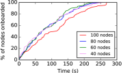
VI-B1 Convergence Time
Fig. 7(a) depicts the empirical cumulative distribution functions (eCDFs) of network convergence times; the X-axis represents time, while the Y-axis gives the cumulative proportion of nodes that have been onboarded. As SNs power on randomly, we identified that congestion is not a big challenge to onboarding–new nodes get onboarded rapidly. No clear trend can be seen between the , , and node scenarios. However, the -node scenario clearly converges slower, suggesting that as density increases, radio interference has increasingly adverse impact on onboarding. We believe that with greater densities, onboarding may not converge. The worst-case convergence time across all runs was seconds (5 minutes, 14.6 seconds), not much longer than the average case for nodes, seconds (4 minutes, 31.0 seconds). We believe this to be an acceptable convergence delay, as the process only occurs once.
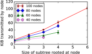
VI-B2 Transmission Burden
The amount of energy consumed by a node is dominated by wireless transmissions. In LASeR, the transmission burden of an SN grows as it serves increasing number of other SNs as a forwarder in the onboarding process. Therefore, we evaluate the transmission burden observed for SNs of varying subtree sizes. Application-introduced bandwidth is not considered here; only LASeR traffic is measured. Anchor nodes are not included in this analysis, as we assume they are not subject to power constraints.
Fig. 7(b) summarizes our analysis of this transmission burden under increasing subtree size and network node density; subtree sizes are on the X-axis, and total KiB transmitted is on the Y-axis. A clear linear trend is visible under increasing subtree size; as expected, transmission burden is approximately proportional to the number of nodes being served in the subtree. Additionally, notice that increasing node density results in overall larger transmission burdens, a pattern resulting from interference-related retransmissions.
In our simulations, a single node must transmit an average of kibibytes (KiB) throughout the onboarding process; while this is a reasonable burden, we notice that this burden is compounded by increasing the number of downstream SNs. For this reason, care must be taken to avoid creating large subtrees in a real IoT deployment.
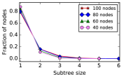
VI-B3 Subtree Size and Distance from Anchor
Fig. 7(c) depicts the empirical probabilities of each observed subtree size; the X-axis gives subtree sizes, and the Y-axis gives the likelihood that a node would host a subtree of that size. On average, 83.6% of nodes served no children, and thus would experience the minimum transmission burden. In accordance with intuition, hop-count distance from an anchor was correlated to subtree size; on average, 79.2% of nodes were only one hop away from the anchor. However, we observed that increasing node density increased the average subtree size and path length, even though the nodes’ physical distances from the anchor were unchanged. This is because increased density increases interference, thus reducing the effective transmission range of nodes and increasing the chance of SNs to use intermediate forwarders to reach the AN.

VI-C Increasing Distance
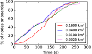
In the previous subsection, we focused on increasing the number of nodes deployed in a fixed m2 area. We now evaluate a second set of scenarios, wherein the node count is fixed at 100 and the deployment area is varied. This increases sparseness, causing creation of longer paths from SNs to the AN and bigger subtrees. We chose areas of m2 (0.0025 km2), m2 (0.01 km2), m2 (0.04 km2), and m2 (0.16 km2). Again, results are averaged over 20 runs. The time at which nodes come online is exponential with seconds. With a few exceptions, trends are similar to those observed in the fixed-area scenario set.
VI-C1 Convergence Time
The convergence times under the 100-node scenarios are visualized as eCDFs in Fig. 8(a). We again see that the densest scenario reaches final convergence slowest, however it is notable that the sparsest scenario ( km2) has a slower initial progression. An inflection point is visible between 100-120 seconds, suggesting that connectivity is poor prior to a sufficient number of nodes (which will serve as intermediate forwarders) being onboarded.
VI-C2 Transmission Burden
The transmission burdens for nodes with each observed subtree size are visualized in Fig. 8(b). Again, there is a clear trend of increased burden under higher densities, when considering similarly-sized subtrees; this is due to interference-related retransmissions. However, we can see that in the sparsest scenario, some nodes host much larger subtrees and thus carry a greater burden. The available energy at these nodes serves as the bottleneck for communication from the downstream nodes. Thus, care must be taken in node placement: nodes’ distances from anchors should be minimized.
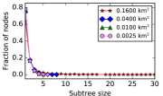
VI-C3 Subtree Size and Distance from Anchor
The observed probability mass function of subtree sizes is given in Fig. 8(c). Again, a majority of nodes host no children; however, in the sparsest case, a few nodes hosting large subtrees are observed. The emergence of large subtrees can be averted by careful node and anchor placement. The distributions of hop-counts in the three densest scenarios are similar to those observed in the fixed-area scenario set. However, in the sparsest scenario a majority of nodes are two hops from an anchor, rather than one hop. This increases latency; thus, it is best to have short paths from SNs to their corresponding AN.
VII Conclusions and Future Work
In this paper, we have proposed LASeR, a secure onboarding and routing framework for NDN-based IoT networks. Scalability is achieved through a hierarchical network design, and very little cryptographic or computational burden. Evaluation by simulations confirmed that LASeR requires minimal network overhead and achieves acceptable onboarding convergence times.
The current implementation of LASeR routes based on node IDs, however an extension is planned to support the advertisement of arbitrary name prefixes. A mechanism to address node mobility with low overhead is also in development. After further validating LASeR in ndnSIM, we intend to implement it on real IoT devices for a live testbed deployment.
References
- Zanella et al. [2014] Andrea Zanella, Nicola Bui, Angelo Castellani, Lorenzo Vangelista, and Michele Zorzi. Internet of things for smart cities. IEEE Internet of Things Journal, 1(1):22–32, 2014.
- Baccelli et al. [2014] E. Baccelli, C. Mehlis, O. Hahm, T. C. Schmidt, and M. Wählisch. Information centric networking in the IoT: experiments with NDN in the wild. arXiv:1406.6608, 2014.
- Zhang et al. [2010] L. Zhang, D. Estrin, J. Burke, V. Jacobson, J. D. Thornton, D. K. Smetters, B. Zhang, G. Tsudik, D. Massey, C. Papadopoulos, et al. Named data networking (NDN) project. NDN Technical Report NDN-0001, 2010.
- Hong et al. [2013] K. Hong, D. Lillethun, U. Ramachandran, B. Ottenwälder, and B. Koldehofe. Mobile fog: A programming model for large-scale applications on the internet of things. In ACM SIGCOMM Wksh. on Mobile Cloud Computing, 2013.
- Kannhavong et al. [2007] B. Kannhavong, H. Nakayama, Y. Nemoto, N. Kato, and A. Jamalipour. A survey of routing attacks in mobile ad hoc networks. IEEE Wireless Communications, 14(5), 2007.
- Amadeo et al. [2014] M. Amadeo, C. Campolo, A. Iera, and A. Molinaro. Named data networking for IoT: an architectural perspective. In European Conference on Networks and Communications, 2014.
- Datta and Bonnet [2016] S. K. Datta and C. Bonnet. Integrating named data networking in internet of things architecture. In IEEE Intl. Conference on Consumer Electronics-Taiwan, 2016.
- Ravindran et al. [2013] R. Ravindran, T. Biswas, X. Zhang, A. Chakraborti, and G. Wang. Information-centric networking based homenet. In IFIP/IEEE Intl. Symposium on Integrated Network Mgmt., 2013.
- Amadeo et al. [2015a] M. Amadeo, C. Campolo, A. Iera, and A. Molinaro. Information centric networking in IoT scenarios: The case of a smart home. In IEEE Intl. Conference on Communications, 2015a.
- Burke et al. [2012] J. Burke, A. Horn, and A. Marianantoni. Authenticated lighting control using named data networking. NDN Technical Report NDN-0011, 2012.
- Meisel et al. [2010] M. Meisel, V. Pappas, and L. Zhang. Ad hoc networking via named data. In ACM Intl. Wksh. on Mobility in the Evolving Internet Architecture, 2010.
- Amadeo et al. [2015b] M. Amadeo, C. Campolo, and A. Molinaro. Forwarding strategies in named data wireless ad hoc networks: Design and evaluation. Journal of Network and Computer Applications, 50, 2015b.
- Winter et al. [2012] T. Winter, P. Thubert, A. Brandt, J. Hui, R. Kelsey, P. Levis, K. Pister, R. Struik, J. P. Vasseur, and R. Alexander. RPL: IPv6 routing protocol for low-power and lossy networks. RFC 6550, 2012.
- Enguehard et al. [2016] M. Enguehard, R. Droms, and D. Rossi. On the cost of secure association of information centric things. In ACM Conference on Information-Centric Networking, 2016.
- Compagno et al. [2016] A. Compagno, M. Conti, and R. Droms. OnboardICNg: a secure protocol for on-boarding IoT devices in ICN. In ACM Conference on Information-Centric Networking, 2016.
- Bellare and Rogaway [1993] M. Bellare and P. Rogaway. Entity authentication and key distribution. In Annual Intl. Cryptology Conference, 1993.
- Bersani and Tschofenig [2007] F. Bersani and H. Tschofenig. The EAP-PSK protocol: A pre-shared key extensible authentication protocol (EAP) method. RFC 4764, 2007.
- Kaliski [2000] B. Kaliski. PKCS #5: Password-Based Cryptography Specification Version 2.0. RFC 2898, 2000.
- Hoque et al. [2013] A. K. M. Hoque, S. O. Amin, A. Alyyan, B. Zhang, L. Zhang, and L. Wang. NLSR: named-data link state routing protocol. In ACM SIGCOMM Wksh. on Information-Centric Networking, 2013.
- Mastorakis et al. [2015] S. Mastorakis, A. Afanasyev, I. Moiseenko, and L. Zhang. ndnSIM 2.0: A new version of the NDN simulator for NS-3. NDN Technical Report NDN-0028, 2015.
- Shi and Zhang [2012] J. Shi and B. Zhang. NDNLP: A link protocol for NDN. NDN Technical Report NDN-0006, 2012.