JEDI collaboration
Phase locking the spin precession in a storage ring
Abstract
This letter reports the successful use of feedback from a spin polarization measurement to the revolution frequency of a 0.97 GeV/ bunched and polarized deuteron beam in the Cooler Synchrotron (COSY) storage ring in order to control both the precession rate ( kHz) and the phase of the horizontal polarization component. Real time synchronization with a radio frequency (rf) solenoid made possible the rotation of the polarization out of the horizontal plane, yielding a demonstration of the feedback method to manipulate the polarization. In particular, the rotation rate shows a sinusoidal function of the horizontal polarization phase (relative to the rf solenoid), which was controlled to within a one standard deviation range of rad. The minimum possible adjustment was 3.7 mHz out of a revolution frequency of 753 kHz, which changes the precession rate by 26 mrad/s. Such a capability meets a requirement for the use of storage rings to look for an intrinsic electric dipole moment of charged particles.
pacs:
13.40.Em, 11.30.Er, 29.20.D, 29.20.dg, 29.20.dbOver the last few decades, the importance of polarized beams has been demonstrated in numerous experiments at colliders as well as at storage rings such as the Cooler Synchroton COSY. Recently the emphasis of such experiments has started to shift from nuclear and hadron physics to precision measurements. This letter describes the successful effort to use measurements of the polarization of a storage ring deuteron beam in a feedback loop to control in real time the rate of precession in the horizontal (ring) plane and the phase of that rotating polarization relative to an external reference. This work was carried out in the context of the effort to search for an intrinsic electric dipole moment (EDM) of charged particles circulating in the ring jed . Applications in other fields include the manipulation of the polarisation vector, where regular spin rotators are not practical.
An EDM aligned along the particle spin axis is CP-violating and any observation of such a moment would be a signal of new physical processes possibly related to the matter-antimatter asymmetry of the universe Engel et al. (2013); Canetti et al. (2012). An EDM may be observed by measuring the rate of spin precession in an external electric field. For charged particles, confinement in a storage ring exposes them to the particle rest frame electric field that closes the storage ring orbit. To work best for small EDMs, the beam polarization should begin parallel to the particle velocity (and perpendicular to the radial electric field) and precess, due to the EDM, into the vertical direction where that polarization component may be measured in a scattering experiment. Since the precession due to the magnetic moment of a particle is different in electric and magnetic fields (compared to the amount by which the particle path is bent), some combination of and bending fields may be found that allows the reference particle to travel in a “frozen-spin” configuration in which the polarization and the velocity remain aligned. But maintaining this alignment over a thousand seconds Guidoboni et al. (2016) for a statistically significant measurement requires control of the rotation rate at the level of parts per billion; hence real time feedback from a continuously running polarization measurement (available at high precision Eversmann et al. (2015)) is mandatory for any such EDM experiment.
The frozen-spin configuration is not the only possibility to observe an EDM. It has been proposed that precession of the EDM may be achieved through the use of a radio frequency (rf) Wien filter with a vertical magnetic field Morse et al. (2013); Slim et al. (2016) operating at a harmonic frequency of the horizontal spin precession in the plane of a purely magnetic storage ring. In this case both the precession rate and phase relative to the Wien filter rf signal must be controlled. Here, we report on the first successful installation and operation of a feedback system fulfilling these requirements.
The measurements presented here were performed at the Cooler Synchrotron COSY at the Forschungszentrum Jülich Maier (1997). A vector polarized deuteron beam was injected at time and accelerated to a momentum of 970 MeV/. The beam intensity was approximately deuterons per fill. The vector polarization was perpendicular to the ring plane and was alternated from cycle to cycle from upward to downward direction. The corresponding values for the polarization were and . After acceleration the beam was electron-cooled for to reduce the beam emittance. A radio frequency cavity to bunch the beam was used throughout the long cycle. Starting at the beam was slowly extracted onto an internal carbon target by applying a white noise electric field. Elastically scattered deuterons were detected in scintillation detectors consisting of rings and bars around the beam pipe. The detector covers a range from to degrees in polar angle and is segmented in four regions in the azimuthal angle (up, down, left and right). The elasticity of the event was guaranteed by stopping the deuterons in the outer scintillator ring and measuring their energy deposition Bagdasarian et al. (2014). The left-right asymmetry gives access to the vertical polarization, the up-down asymmetry is sensitive to the polarization perpendicular to the momentum vector in the horizontal plane of the ring. At an rf solenoid was used to rotate the polarization from the initially vertical direction into the horizontal plane.
Once the polarization is rotated out of the vertical direction, its horizontal component starts to precess around the vertical axis. Defining the spin motion in the rest frame of the particle, the precession frequency is
| (1) |
where is the spin tune, the Lorentz factor, the gyromagnetic anomaly and the revolution frequency. Note that the sign of indicates the direction of the spin rotation. In order to rotate the polarization vector effectively, the rf solenoid has to run at a resonance frequency, which is given as
| (2) |
For this experiment the solenoid was operated at (). Table 1 summarizes the most important parameters of the experiment.
In the further course of the cycle the solenoid was also used to restore the vertical polarization, thus providing a test for the feedback system. As the solenoid field only acts on the polarization components perpendicular to the solenoid field, which is aligned along the beam direction, its effective strength is largest if the maximum of the rf solenoid field coincides in time with the horizontal polarization being radial and vanishes if both are parallel. The rate of build-up of vertical polarization is thus proportional to , where is the relative phase between the rf signal and the spin precession at the location of the rf solenoid. corresponds to the case where the polarization vector is parallel to the magnetic field of the solenoid when it is at its maximum value. The slope of the polarization build-up as a function of is thus a measure how well the relative phase between the two is under control. For this, the solenoid was again switched on at s at low field strength.
| deuteron momentum | |
|---|---|
| rel. velocity | 0.459 |
| Lorentz factor | 1.126 |
| slip factor | -0.58 |
| gyromagnetic anomaly | |
| revolution frequency | 752543 Hz |
| precession frequency | 121173 Hz |
| resonance frequency | 873716 Hz |
| cycle length | 200 s |
In general, the relative phase between the rf signal and the spin precession is time dependent and defined as
| (3) |
where is the time in the cycle, is the time the measurement starts and is the phase at . As the solenoid is located at a fixed position in the ring, the time is sampled as where denotes the turn number:
| (4) |
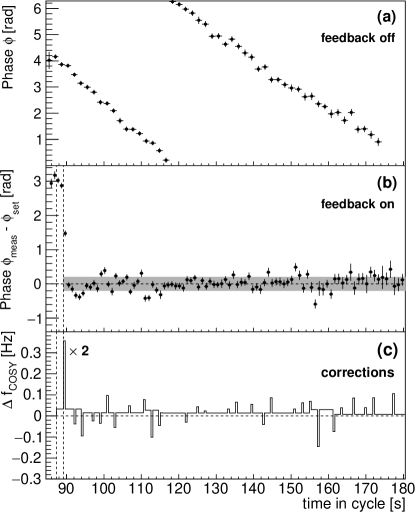
As long as Eq. (2) is fulfilled, will remain constant (modulo ), since the term in the parentheses is an integer. However, even for a small mismatch between the resonance frequency and , the value of will continuously change and the polarization build-up will be diminished or even canceled. If one accepts the build-up to drop to 80% at the end of a cycle (corresponding to and ), both frequencies have to be adjusted with a precision better than . As discussed in Ref. Eversmann et al. (2015), both the reproducibility and the stability of the spin tune are of the order of to . Figure 1(a) provides an example for the variation of over one cycle without a feedback system. Starting at an arbitrary value the phase is continuously changing over the whole cycle. With the same initial settings other cycles show both weaker and stronger time dependencies. Therefore, an active feedback system is essential for keeping within the desired interval of .
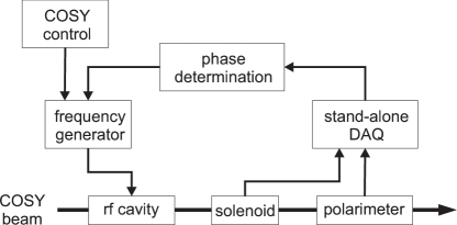
The basic principle of the feedback system is to control the spin precession frequency by varying and to match its phase to the radio frequency of the solenoid. Figure 2 illustrates schematically the feedback control loop. In a first step, the phase of the spin precession is measured using a polarimeter and a stand-alone data acquisition system as described in Eversmann et al. (2015). Then, the relative phase is determined, which corresponds to the difference between the solenoid phase and the spin precession phase. Both phases are measured using the same reference clock. The additional constant offset originates from the relative position of polarimeter and rf solenoid in the ring and from cable delays. The typical measurement period for each data point is about depending on the available intensity of the beam, which is continuously extracted onto the target during the cycle. The purpose of the feedback is twofold: First, the phase has to be adjusted to a predefined value to define and to reproduce the experimental conditions. This is done by running off-resonance for a short period of time (of the order of , e.g. in Fig. 1(b) at s) until the desired phase has been reached. It is also used to compensate larger deviations during the course of the cycle. Second, the resonance condition, defined in Eq. (2) has to be fulfilled in order to keep constant. This is achieved by introducing a corresponding offset to the revolution frequency .
The necessary frequency change can be calculated using the derivative of Eq. (4):
| (5) |
While the first term originates from the different arrival time at the solenoid, the second term describes the change of the spin tune:
| (6) |
where is the relative particle velocity and the so-called slip factor, which connects a change in momentum into a change in revolution frequency. Using values given in Tab. 1 one obtains
| (7) |
With a minimum step size of offered by the standard COSY frequency generator it was possible to induce phase adjustments in steps of .
Figure 1(b) shows the phase difference versus time while the feedback system was active. In Fig. 1(c) the changes to the revolution frequency are illustrated. The feedback system started monitoring the phase at when the polarization vector was turned into the horizontal plane. While a first correction of the phase drift was applied at the first vertical dashed line, the pulse at the second dashed line moved the phase to the predefined value . Once this phase had been reached it was kept stable over the remaining cycle. The resulting phase distribution has a width of , indicated by the shaded band in Fig. 1b, which is well below the allowed variation defined by .

Fig. 1(b) already proves the functionality of the feedback system. In order to confirm that the relative phase can really be set to an arbitrary value between and , the phase dependent build-up of the vertical polarization was measured. The basic principle of the experiment is shown in Fig. 3.
Once the polarization vector had been turned into the horizontal plane (first vertical dashed line), the feedback system was switched on, maintaining the relative phase at a predefined value . At (second dashed line) the solenoid was switched back on at a reduced strength causing the polarization to rotate slowly out of the horizontal plane — either upwards or downwards depending on the selected value of . The field integral of the solenoid was about . This corresponds to a maximal polarization rotation of 50 mrad/s.
Figure 3(a) qualitatively shows the amplitude of the solenoid. Figure 3(b) shows the asymmetry proportional to the polarization in the vertical direction, obtained from the counting rates in the left () and right () detector segments. Figure 3(c) shows the asymmetry proportional to the amplitude of the polarization in the horizontal plane. is obtained from the oscillating event rates in the upper and lower segment of the detector, and as described in Ref. Eversmann et al. (2015).
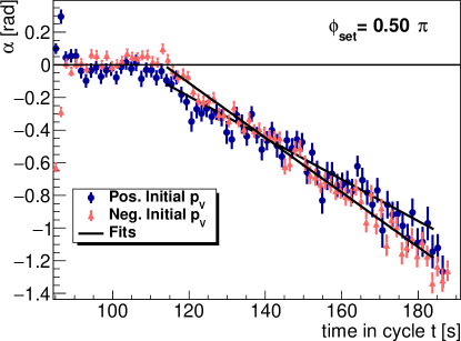
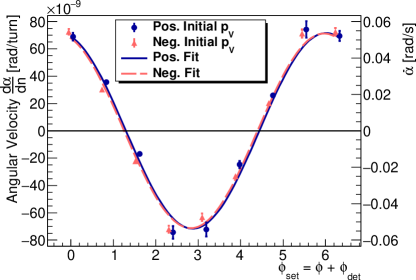
The polarization rotation is analyzed by examining the angle between the polarization vector and the horizontal plane. is independent on the initial degree of polarization and is expected to either increase or decrease linearly with a slope proportional to . Figure 4 shows as function of time in cycle for . Both initial polarization states show a similar slope. Figure 5 shows the fitted slopes as a function of the nominal phase . The rate of build-up proportional to is another striking proof that the method works.
In conclusion, we have shown that the high precision measurement of the spin tune, discussed in Eversmann et al. (2015), can be used to perform a real-time measurement of the relative phase between the spin precession and an external radio frequency device. This has been used for the first time to implement an active feedback system to stabilize this phase at a level of and to reproduce the phase dependence of the polarization rotation in an rf solenoid. As the sensitivity to phase variations is the same for the rf Wien filter, this is an essential prerequisite towards the first measurement of an EDM in a storage ring. In addition, such a feedback system can also be used in the frozen-spin method Anastassopoulos et al. (2016), where the polarization has to be kept aligned to the momentum vector in the horizontal plane.
Acknowledgements.
The authors wish to thank the staff of COSY for providing excellent working conditions and for their support concerning the technical aspects of this experiment. This work has been financially supported by Forschungszentrum Jülich GmbH, Germany, via COSY FFE, by an ERC Advanced-Grant (srEDM # 694390) of the European Union, the European Union Seventh Framework Programme (FP7/2007-2013) under Grant Agreement No. 283286, the Shota Rustaveli National Science Foundation of the Republic of Georgia, by a Grant from the Russian Science Foundation (grant number RNF-16-12-10151), and by IBS-R017-D1-2017-a00.References
- (1) JEDI Collaboration, http://collaborations.fz-juelich.de/ikp/jedi/index.shtml.
- Engel et al. (2013) J. Engel, M. J. Ramsey-Musolf, and U. van Kolck, Progress in Particle and Nuclear Physics 71, 21 (2013).
- Canetti et al. (2012) L. Canetti, M. Drewes, and M. Shaposhnikov, New J. Phys. 14, 095012 (2012), arXiv:1204.4186 [hep-ph] .
- Guidoboni et al. (2016) G. Guidoboni et al. (JEDI), Phys. Rev. Lett. 117, 054801 (2016).
- Eversmann et al. (2015) D. Eversmann et al. (JEDI), Phys. Rev. Lett. 115, 094801 (2015), arXiv:1504.00635 [physics.acc-ph] .
- Morse et al. (2013) W. M. Morse, Y. F. Orlov, and Y. K. Semertzidis, Phys. Rev. ST Accel. Beams 16, 114001 (2013).
- Slim et al. (2016) J. Slim et al., Nucl. Instrum. Meth. A828, 116 (2016), arXiv:1603.01567 [physics.ins-det] .
- Maier (1997) R. Maier, Nucl. Instrum. Meth. A390, 1 (1997).
- Bagdasarian et al. (2014) Z. Bagdasarian et al., Phys. Rev. ST Accel. Beams 17, 052803 (2014).
- Anastassopoulos et al. (2016) V. Anastassopoulos et al., Rev. Sci. Instrum. 87, 115116 (2016), arXiv:1502.04317 [physics.acc-ph] .