Effects of heavy-ion irradiation on FeSe
Abstract
We report the effects of heavy-ion irradiation on FeSe single crystals by irradiating Uranium up to a dose equivalent matching field of = 16 T. Almost continuous columnar defects along the -axis with a diameter 10 nm are confirmed by high-resolution transmission electron microscopy. is found to be suppressed by introducing columnar defects at a rate of d/d -0.29KT-1, which is much larger than those observed in iron pnictides. This unexpected large suppression of in FeSe is discussed in relation to the large diameter of the columnar defects as well as its unique band structure with a remarkably small Fermi energy. The critical current density is first dramatically enhanced with irradiation reaching a value over 2105 A/cm2 (5 times larger than that of the pristine sample) at 2 K (self-field) with = 2 T, then gradually suppressed with increasing . The -pinning associated with charge-carrier mean free path fluctuations, and the -pinning associated with spatial fluctuations of the transition temperature are found to coexist in the pristine FeSe, while the irradiation increases the contribution from -pinning, and makes it dominant over = 4 T.
- PACS numbers
-
74.70.Xa,74.62.En,74.25.Sv,74.25.Wx
pacs:
Valid PACS appear hereI introduction
FeSe composed of only stackings Fe-Se layers Hsu et al. (2008) has the simplest crystal structure in iron-based superconductors (IBSs), and is usually regarded as the parent compound. It also manifests very intriguing properties such as the nematic state without long-range magnetic order McQueen et al. (2009a), crossover from Bardeen-Cooper-Schrieffer (BCS) to Bose-Einstein-condensation (BEC) Kasahara et al. (2014), Dirac-cone-like state Onari et al. (2016); Zhang et al. (2015); Sun et al. (2016a), and quasi-2D Fermi surface at temperatures below the structure transition Watson et al. (2015); Terashima et al. (2014); Sun et al. (2016b). Recently, an unexpected high with a sign of superconductivity over 100 K observed in monolayered FeSe Ge et al. (2015) makes this system a promising candidate for achieving high-temperature superconductivity and probing the mechanism of superconductivity.
To understand these intriguing properties and the unexpected high in FeSe system, it is crucial to know the gap structure, which is unfortunately still under debate. A nodal gap was reported based on the observation of the V-shaped STM spectrum, a nearly linearly temperature dependent penetration depth at low temperatures, and a large residual thermal conductivity Kasahara et al. (2014). However, nodeless gap structure is also claimed by the low-temperature specific heat Lin et al. (2011, 2016), lower critical field, and thermal conductivity measurements reported by other groups Dong et al. (2009); Bourgeois-Hope et al. (2016). Such controversy may come from the difference in sample quality. Nodes in the superconducting gap of FeSe could be symmetry-unprotected accidental nodes Kreisel et al. (2015). Besides, there have been few efforts on bulk FeSe to distinguish the inter-band sign-reversed state Mazin et al. (2008) and the sign-preserving state Kontani and Onari (2010).
Introduction of nonmagnetic scattering centers have been proved to be an effective method to identify the gap structures of novel superconductors Alloul et al. (2009); Nakajima et al. (2010); Taen et al. (2013). By introducing point defects by light-particle irradiations, such as electrons and protons, a clear suppression of was observed in both cuprates and iron pnictides, and was attributed to the sign change of the order parameter in -wave Alloul et al. (2009); Rullier-Albenque et al. (2012) and Wang et al. (2013) (or competition between and via inter- and intra-band scatterings Saito et al. (2013); Hosono and Kuroki (2015)), respectively. In the case of correlated disorders created by heavy-ion irradiation, such as columnar defects, an obvious suppression of together with the increase in the normal state resistivity has been reported in cuprates Bourgault et al. (1989). However, the shows only a small or nondetectable change in iron pnictides Nakajima et al. (2009); Tamegai et al. (2012); Kim et al. (2010); Murphy et al. (2013); Salovich et al. (2013); Fang et al. (2012, 2013); Kihlstrom et al. (2013). The temperature dependence of the penetration depth in Co or K substituted BaFe2As2 was found to change after heavy-ion irradiation, consistent with the scenario Murphy et al. (2013); Salovich et al. (2013). On the other hand, the columnar defects created by heavy-ion irradiation are also strong pinning centers due to the geometrical similarity with vortices, which are already proved to be effective to the enhancement of critical current density Nakajima et al. (2009); Tamegai et al. (2012); Fang et al. (2012, 2013); Kihlstrom et al. (2013). Their controllability is also advantageous in the study of vortex physics. Thus, studies of the effects of heavy-ion irradiation on FeSe is instructive to the understanding of its pairing mechanism and vortex physics, which is important for the application of this material.
Unfortunately, the effects of heavy-ion irradiation on pure FeSe is still left unexplored. In this paper, we report a systematic study of heavy-ion irradiation in high-quality FeSe single crystals by Uranium irradiation. is found to change sensitively with the density of columnar defects with an unexpected large suppression rate d/d -0.29KT-1. The critical current density is first dramatically enhanced with irradiation up to a dose-equivalent matching field = 2 T, and then gradually suppressed with further increasing the dose. Origins of the large suppression rate as well as the vortex pinning mechanism are discussed in detail.
II experiment
High-quality FeSe single crystals were grown by the vapor transport method Böhmer et al. (2013). Fe and Se powders were thoroughly mixed by grounding in a glove box for more than 30 min, and sealed in an evacuated quartz tube together with mixture of AlCl3 and KCl powders. The quartz tube with chemicals was loaded into a horizontal tube furnace with one end heated up to 400 ∘C, while the other end was kept at 250 ∘C. After more than 35 days, single crystals with dimensions over 11 mm2 can be obtained in the cold end. The obtained crystals are of high quality with a sharp superconducting transition width 0.5 K from susceptibility measurements, and large residual resistivity ratio (RRR) 33 as reported in our previous publications Sun et al. (2015, 2016a).
Single crystals used for the irradiation were selected from the same batch, and were confirmed to show similar properties in the pristine state with negligible piece dependent and . Before the irradiation, single crystals were cleaved to thin plates with thickness 20 m along the -axis, which is much smaller than the projected range of 2.6 GeV Uranium for FeSe of 60 m, calculated by SRIM-2008 (the Stopping and Range of Ions in Matter-2008) Ziegler et al. (1985). The 2.6 GeV Uranium was irradiated parallel to the -axis of the crystal at room temperature. The Uranium irradiation up to a dose equivalent magnetic field called matching field () of 16 T was performed at RI Beam Factory operated by RIKEN Nishina Center and the Center for Nuclear Study of The University of Tokyo. The structure of the crystal was characterized by means of X-ray diffraction (XRD) with Cu-K radiation. Cross-sectional observations of the irradiated FeSe were performed with a high-resolution scanning transmission electron microscopy (STEM) (JEOL, JEM-3000F). Magnetization measurements were performed using a commercial SQUID magnetometer (MPMS-XL5, Quantum Design).
III results and discussion
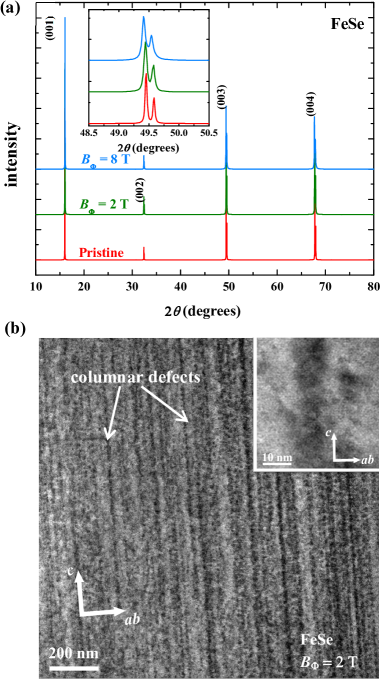
Figure 1(a) shows the single crystal XRD patterns for FeSe before and after the irradiation by Uranium with = 2 T and 8 T. Only the (00) peaks are observed, suggesting that the crystallographic -axis is perfectly perpendicular to the plane of the single crystals. After the irradiation, the positions of (00) peaks are almost unchanged to those in the pristine sample, which can be seen more clearly in the enlarged part of (003) peaks shown in the inset of Fig. 1(a). The almost identical XRD patterns for the crystals before and after the irradiation indicates that the columnar defects along -axis created by Uranium irradiation do not affect the lattice constant .
Figure 1(b) shows a STEM image of the cross section along -axis in FeSe irradiated by Uranium with = 2 T, where we can clearly identify that the morphology of defects along the projectile is in columnar shape (black lines as pointed out in the figure) and almost continuous along the -axis. A typical high-resolution STEM observation of the defect shown in the inset of Fig. 1(b) reveals that the diameter of the columnar defects in the irradiated FeSe is 10 nm. This size is very close to that of the amorphous columnar defects in high-temperature cuprate superconductors, but much larger than that of 2-5 nm in Au-irradiated Ba(Fe0.93Co0.07)2As2 Nakajima et al. (2009). Actually, the shape and size of the columnar defects created by the irradiation are dependent not only on the mass and energy of the ions, but also on the properties of the crystal itself like the thermal conductivity and carrier density Zhu et al. (1993).
According to the study by G. Szenes Szenes (1995) based on magnetic insulators, the radius of the columnar defects, , created by the heavy-ion irradiation can be expressed by the formula below:
| (1) | |||
| (2) |
where is the electronic stopping power, is the threshold value, and (0) is related to the thermal diffusivity. The eq.(1) is the situation for smaller than 1 nm, while the eq.(2) is the case for larger as shown in the Fig. 1 of Ref. Szenes (1995). If we simply apply the above expression to the IBSs, the radius is proportional to (0)(/)1/2 since the value of in IBSs are found to be in the range of 2-10 nm. The values of can be calculated by the SRIM program, which are comparable for 2.6 GeV Uranium irradiated BaFe2As2 (4.8 keV/Å) and FeSe (4.2 keV/Å). The threshold value is expressed as = (0)/, where is the density, is the specific heat, is a constant, = - is the difference between the melting temperature and the target temperature Szenes (1995). Substituting the expression of into eq.(2), the prefactor (0) can be canceled, and the is found to be proportional to (/(-))1/2. The values of are 5.9 g/cm3 and 4.7 g/cm3 for BaFe2As2 and FeSe, respectively. The values of at 200 K are 1.51 mJ/gK2 (600 mJ/molK2) for BaFe2As2 Rotundu et al. (2010), and 1.78 mJ/gK2 (240 mJ/molK2) for FeSe Abdel-Hafiez et al. (2016). The of FeSe is 1238 K Okamoto (1991), while it is reported above 1443 K for BaFe2As2 Morinaga et al. (2009). is 300 K for both cases since the irradiation was performed at room temperature. Putting all the values listed above into the eq.(2), we can roughly estimate that (FeSe)/(BaFe2As2) 1.14, the trend of which is consistent with the STEM observation.
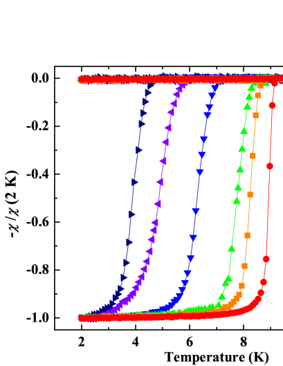
Figure 2 shows the temperature dependence of the normalized magnetic susceptibilities -/(2 K) at 5 Oe for the pristine and Uranium irradiated FeSe with = 1, 2, 4, 8, and 16 T. The pristine FeSe displays a superconducting transition temperature 9.2 K, which is evidently suppressed gradually with increasing . When the = 16 T, the value of is reduced to below 5 K. On the other hand, the sharp superconducting transition width observed in the pristine crystal changes little after the irradiation, which confirms that the effect of columnar defects on superconductivity is homogeneous.
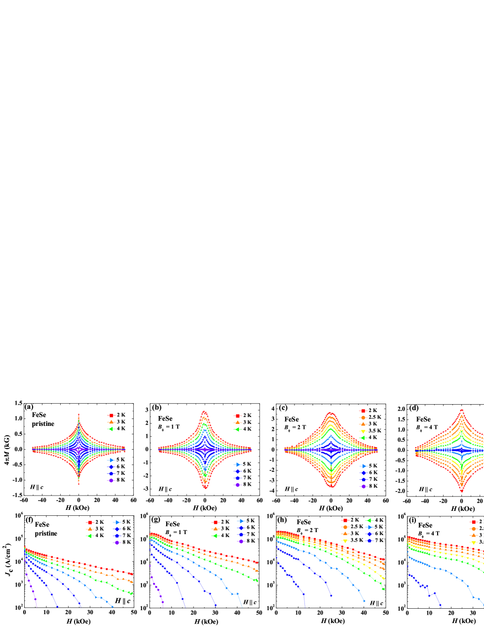
To study the effects of columnar defects to the critical current density, we first measured magnetic hysteresis loops (MHLs) at several temperatures for the pristine and Uranium irradiated crystals. Typical results of the MHLs for the pristine and irradiated crystals with = 1, 2, 4, and 8 T are depicted in Fig. 3(a) - (e), respectively. All the MHLs are almost symmetric, indicating that the bulk pinning is dominant in all crystals. However, the shape of the MHLs is obviously changed after the irradiation, especially the central peak around zero field. For the pristine crystal, a sharp central peak is observed, while it becomes broader after the irradiation and a small dip-like behavior can be observed near zero field in the crystals with = 1 and 2 T. After further increase in the density of columnar defects, the broader central peak becomes sharper again as in the crystals with = 4 and 8 T.
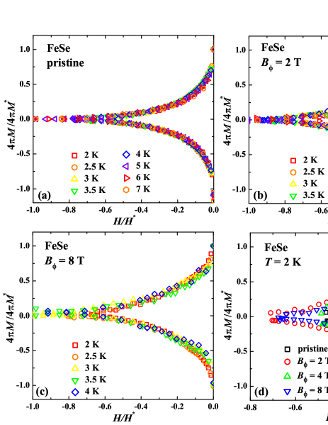
The shape change of MHLs after irradiation can be seen more clearly in the scaled plot. As has been demonstrated in several superconductors, the MHLs at different temperatures can be well scaled onto one curve by choosing appropriate reducing parameters and , if one single pinning mechanism is dominant Perkins et al. (1995); Oussena et al. (1994); Dewhurst et al. (1996, 2000). The scaled MHLs at several temperatures for the pristine and Uranium irradiated FeSe with typical doses of = 2 T, and 8 T are shown in Figs. 4(a)-(c), respectively. The parameter is selected as the maximum value of the magnetization, and the is the irreversibility field obtained by extrapolating to zero in vs curves Sun et al. (2015). For the pristine crystal, the MHLs measured at different temperatures can be well scaled, which is consistent with our previous report that FeSe is dominated by sparse, strong point-like pinning from nanometer-sized defects or imperfections Sun et al. (2015). After introducing columnar defects by Uranium irradiation, which are strong pinning centers in nature and pin the vortices strongly as discussed above, two kinds of strong pinnings coexist in the crystal. Thus, the scaling of MHLs fails in the irradiated crystals, and one typical result for the crystal with = 2 T was shown in Fig. 4(b). When the value of is increased larger than the maximum applied field 5 T in the current experiment, all the vortices can be pinned by the columnar defects. In this case, only one kind of pinning centers is dominant, i.e., the columnar defects, which makes the scaling of MHLs becomes valid again as seen in Fig. 4(c) for the crystal of = 8 T. The shape change in MHLs caused by the irradiation can be seen more directly in Fig. 4(d), which shows the scaled MHLs at 2 K for the pristine and irradiated crystals with = 2 T, 4 T and 8 T. Such structural evolution in MHLs indicates the change of the pinning mechanism accompanied by the irradiation, which will be discussed in detail later.
Before discussing the origin of the shape change observed in MHLs, we first calculate the critical current density, , from the MHLs by using the extended Bean model Bean (1964)
| (3) |
where M is Mdown - Mup, Mup [emu/cm3] and Mdown [emu/cm3] are the magnetization when sweeping fields up and down, respectively, a [cm] and b [cm] are sample widths (a b). Magnetic field dependence of for the pristine and irradiated crystals with = 1, 2, 4, and 8 T are shown in Figs. 3(f) - (j), respectively. Obviously, the value of is enhanced after introducing the columnar defects and reaches the maximum value for = 2 T. For larger than 2 T, the value of decreases with further increase in dose.
Now, we turn back to the discussion of the shape change in the MHLs after the irradiation. The broad central peak accompanied with a dip-like structure in MHLs observed in samples with strong correlated pinning along -axis is explained by the self-field () effect Tamegai et al. (2012); Mikitik and Brandt (2000). When the magnetic field is smaller than the , flux lines in a thin sample are strongly curved, which makes the pinning by columnar defects ineffective in large areas of the crystal, and hence reduces the irreversible magnetization. When the field is increased to , the flux lines are straightened up in the sample. Thus, the pinning by columnar defects become effective, and irreversible magnetization reaches the maximum value. This scenario can explain the dip structure in MHLs of crystals with = 1 and 2 T, where the self-field reaches the maximum value ( , where is the thickness, and is 20 m for all the crystals). Actually, the location of peak in MHLs at 1 kOe in the crystal with = 2 T at 2 K roughly agrees with the self-field at 2 K for this crystal of 0.5 kG. When the is increased larger than 2 T, the value of is decreased, which makes the too small to cause the dip-like structure, while the central peak is still broader than the pristine one.
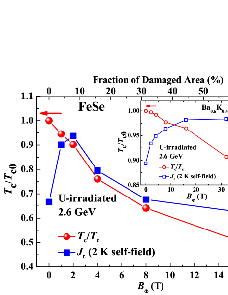
The effects of columnar defects are summarized by the normalized and the self-field at 2 K as a function of as shown in Fig. 5. is determined by the onset of diamagnetism for the zero-field-cooled susceptibility shown in Fig. 2. Evidently, the value of is considerably suppressed with increasing , and the suppression of is roughly in a linear function, with a slope of d/d 3.2% T-1 (-0.29K T-1), which is much larger than other IBSs Tamegai et al. (2012). To directly show the differences between the heavy-ion irradiation effects on FeSe and iron pnitides, we also plot the results of and ’s evolution with increasing for the 2.6 GeV Uranium irradiated Ba0.6K0.4Fe2As2 in the inset of Fig. 5. The data is obtained from Ref. Ohtake et al. (2015). Obviously, the value of is only suppressed less than 5% in Ba0.6K0.4Fe2As2 for = 16 T, which is about one order smaller than that of 50% in FeSe, suggesting a unique pairing mechanism of FeSe.
Before discussing the unexpected large suppression rate by Uranium irradiation in FeSe, it is worth noticing that the heavy-ion irradiation not only creates columnar defects, but may also produce secondary energetic electrons as they lose energy. The secondary electron irradiation can introduce point-like defects, which may act as pairing breaker and suppress unless the gap structure is isotropic -wave. Such an effect is indeed observed in YBa2Cu3O7-δ thin films Biswal et al. (2008) and in similar compounds FeTe1-xSex Massee et al. (2015). However, the electron irradiation has already been reported not to suppress the of FeSe, and instead an unexpected small enhancement of was observed Teknowijoyo et al. (2016). Hence, the large suppression observed here cannot be explained by the effect of the secondary electron irradiation. The large suppression rate may be originated from the much larger damaged areas after the heavy-ion irradiation. As shown in the inset of Fig. 1(b), the diameter of the columnar defects in the irradiated FeSe is 10 nm, which is much larger than that of 2-5 nm observed in irradiated IBSs ”122” system Nakajima et al. (2009); Tamegai et al. (2012). In such a case, the damaged areas in FeSe is 4 - 25 times larger than those in IBSs ”122” system. The fraction of the damaged area without considering the overlap between the defects is also plotted in Fig. 4 as the top axis. Obviously, the fraction of damaged area reaches over 60% for = 16 T. In addition, the coherence length of FeSe is 4.5 nm Hsu et al. (2008), larger than that of 2-3 nm for ”122” system Gurevich (2011), which indicates that the defect areas in FeSe have more influence to the superconducting regions.
Recent STM observations show that twin boundaries in FeSe may act as pairing breakers, which lift the nodes in their neighborhood, and have long-range effects more than one order larger than the coherence length Watashige et al. (2015). The nodes were found to be totally suppressed in the region between two neighboring twin boundaries of 34 nm, which is close to the average distance between columnar defects at = 2 T. Columnar defects may have similar effects to twin boundaries since they are both correlated defects and the width of the damaged areas are similar. Proximity effect between the normal electrons in the damaged region and the Cooper pairs in the superconducting region may be responsible for the suppression of . The much larger suppression of in FeSe compared to other irradiated IBSs may be also related to its unique band structures, where the Fermi energy is remarkably small and comparable to the superconducting gap, suggesting that FeSe is in the crossover regime from BCS to BEC Kasahara et al. (2014). Such an extremely small could be more sensitive to the defects than the large in other IBSs. Local STM observations of the irradiated FeSe are required to clarify this issue, and to find out if the behavior of being sensitive to correlated defects is the common feature of the superconductors residing in the crossover regime from BCS to BEC.
On the other hand, the value of is enhanced dramatically with the irradiation for 2 T. As also shown in Fig. 5 (right axis), the self-field at 2 K is increased about 5 times from 4104 A/cm2 for the pristine crystal to 2105 A/cm2 for the crystals with = 2 T. Such a large value of enhanced is already close to that reported in high-quality FeTe1-xSex single crystals Sun et al. (2013a, 2014). For 2 T, the value of is gradually suppressed with the increase in columnar defects. Similar evolution of with increasing columnar defects is also observed in (Ba0.6K0.4)Fe2As2 Ohtake et al. (2015). As shown in the inset of Fig. 5, the value of for the (Ba0.6K0.4)Fe2As2 is also enhanced maximally about 5-6 times after Uranium irradiated, although its absolute value is larger. Then, the value of decreases with further increase in dose. However, the maximum in the irradiated (Ba0.6K0.4)Fe2As2 is observed with in the range of 20-30 T, which is one order larger than that of FeSe. The nature of the quick enhancement of by small dose of heavy-ion irradiation in FeSe is also advantageous for real application. Although the value of for the pure FeSe single crystal is relatively small, the Te-doped FeSe tapes with over 106 A/cm2 under self-field and over 105 A/cm2 under 30 T at 4.2 K have already been fabricated, which is promising for applications Si et al. (2013). Recently, 1.5 times enhancement of was achieved in FeTe0.5Se0.5 thin film by irradiating with protons Ozaki et al. (2016). Our current results indicate that heavy-ion irradiation with a small dose may be effective in the further enhancement of for the tapes and thin films of FeSe system.
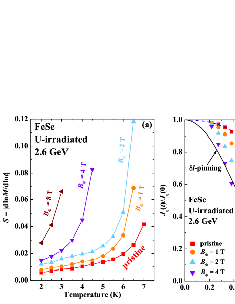
Major pinning mechanisms in type-II superconductors can be classified into two types: the -pinning associated with charge-carrier mean-free path fluctuations, and the Tc-pinning associated with spatial fluctuations of the transition temperature. Typical temperature dependence of for the l-pinning and Tc-pinning are given by Jc(t)/Jc(0) = (1-t2)5/2(1+t2)-1/2 and Jc(t)/Jc(0) = (1-t2)7/6(1+t2)5/6, respectively Griessen et al. (1994). To compare the obtained from the MHLs with the theoretical estimation, we need to consider the magnetic relaxation since there is a finite time delay between the measurement and the preparation of the critical state, and the relaxation rate has been reported to be large in FeSe Sun et al. (2015). The decay of magnetization with time was traced more than 1 hour from the moment when the critical state is prepared. The normalized magnetic relaxation rate can be obtained from = dln/dln, and is shown in Fig. 6(a) for the pristine and Uranium irradiated crystals with = 1, 2, 4, and 8 T measured under 2 kOe. The temperature dependence of shows an obvious crossover from temperature insensitive plateau with a small slope to a steep increase, which is attributed to the crossover from the elastic to plastic creep Sun et al. (2015). After the Uranium irradiation, the crossover is gradually suppressed to lower temperatures, and the plateau region cannot be observed above 2 K in the crystal with = 8 T, which is related to the suppression of . With the values of , we can calculate the (true) without flux creep using the generalized inversion scheme (GIS) with parameters for the three-dimensional single-vortex pinning Schnack et al. (1993); Wen et al. (1995).
The temperature dependence of is normalized by the value of (0) obtained from the extended Maley’s method Miu and Miu (2010) as already performed on the pristine FeSe shown in our previous publication Sun et al. (2015). The temperature dependence of the normalized for the pristine and Uranium irradiated FeSe with = 1, 2, and 4 T is shown in Fig. 6(b) together with the theoretical curves for - and Tc-pinnings. For the pristine crystal, () resides between the predictions of l- and Tc-pinnings, and closer to the curve for Tc-pinning, especially at low temperatures. It indicates that both pinning mechanisms may coexist in the pristine FeSe similar to that reported in FeTe0.6Se0.4 Sun et al. (2013b), Co-doped BaFe2As2 Shen et al. (2010); Taen et al. (2012), and K-doped BaFe2As2 Ghorbani et al. (2012), and the Tc-pinning is more dominant in the pristine crystal. The main pinning centers in the pristine FeSe are found to be nanometer-sized defects or imperfections as reported in our previous publication Sun et al. (2015) and also observed by the STM observations Kasahara et al. (2014). Such defects or imperfections will enhance the spatial variation of mean-free path, and hence contribute to the l-pinning. On the other hand, those defects or imperfections are mainly originated from the Fe nonstoichiometries McQueen et al. (2009b). Since the value of for FeSe is very sensitive to the stoichiometry of Fe to Se McQueen et al. (2009b), those defects or imperfections will also cause spatial fluctuations of , which contribute to the Tc-pinnings. After Uranium irradiation, mean-free path fluctuations should be increased since more defects are introduced. As expected, the temperature dependence of is gradually approaching the theoretical curve for l-pinnings with the increase in . For = 4 T, it almost falls onto the curve for l-pinning except for the low-temperature part, which means that the pinning associated with charge-carrier mean-free path fluctuations becomes dominant.
IV conclusions
In summary, we report a systematic study on the effects of columnar defects on FeSe single crystals by Uranium irradiations. is found to be suppressed by columnar defects at a large rate of d/d -0.29 KT-1. The unexpected large suppression of in FeSe is discussed in relation with the large diameter of the columnar defects as well as its unique band structure with a remarkably small Fermi energy. The critical current density is first dramatically enhanced with irradiation reaching a value over 2105 A/cm2 at 2 K (self-field) for = 2 T, then gradually suppressed with increasing . The coexistence of - and -pinnings in the pristine FeSe (-pinnings are more dominant) is turned into dominant -pinnings after the irradiation.
References
- Hsu et al. (2008) F. C. Hsu, J. Y. Luo, K. W. Yeh, T. K. Chen, T. W. Huang, P. M. Wu, Y. C. Lee, Y.-L. Huang, Y.-Y. Chu, D. C. Yan, and M. K. Wu, Proc. Nat. Acad. Sci. 105, 14262 (2008).
- McQueen et al. (2009a) T. M. McQueen, A. J. Williams, P. W. Stephens, J. Tao, Y. Zhu, V. Ksenofontov, F. Casper, C. Felser, and R. J. Cava, Phys. Rev. Lett. 103, 057002 (2009a).
- Kasahara et al. (2014) S. Kasahara, T. Watashige, T. Hanaguri, Y. Kohsaka, T. Yamashita, Y. Shimoyama, Y. Mizukami, R. Endo, H. Ikeda, K. Aoyama, T. Terashima, S. Uji, T. Wolf, H. von Löhneysen, T. Shibauchi, and Y. Matsuda, Proc. Nat. Acad. Sci. 111, 16309 (2014).
- Onari et al. (2016) S. Onari, Y. Yamakawa, and H. Kontani, Phys. Rev. Lett. 116, 227001 (2016).
- Zhang et al. (2015) Y. Zhang, M. Yi, Z. K. Liu, W. Li, J. J. Lee, R. G. Moore, M. Hashimoto, N. Masamichi, H. Eisaki, S. K. Mo, Z. Hussain, T. P. Devereaux, Z. X. Shen, and D. H. Lu, arXiv:1503.01556 (2015).
- Sun et al. (2016a) Y. Sun, S. Pyon, and T. Tamegai, Phys. Rev. B 93, 104502 (2016a).
- Watson et al. (2015) M. D. Watson, T. K. Kim, A. A. Haghighirad, N. R. Davies, A. McCollam, A. Narayanan, S. F. Blake, Y. L. Chen, S. Ghannadzadeh, A. J. Schofield, M. Hoesch, C. Meingast, T. Wolf, and A. I. Coldea, Phys. Rev. B 91, 155106 (2015).
- Terashima et al. (2014) T. Terashima, N. Kikugawa, A. Kiswandhi, E.-S. Choi, J. S. Brooks, S. Kasahara, T. Watashige, H. Ikeda, T. Shibauchi, Y. Matsuda, T. Wolf, A. E. Böhmer, F. Hardy, C. Meingast, H. v. Löhneysen, M.-T. Suzuki, R. Arita, and S. Uji, Phys. Rev. B 90, 144517 (2014).
- Sun et al. (2016b) Y. Sun, T. Yamada, S. Pyon, and T. Tamegai, Phys. Rev. B 94, 134505 (2016b).
- Ge et al. (2015) J. F. Ge, Z. L. Liu, C. Liu, C. L. Gao, D. Qian, Q. K. Xue, Y. Liu, and J. F. Jia, Nat. Mater. 14, 285 (2015).
- Lin et al. (2011) J. Y. Lin, Y. S. Hsieh, D. A. Chareev, A. N. Vasiliev, Y. Parsons, and H. D. Yang, Phys. Rev. B 84, 220507 (2011).
- Lin et al. (2016) J. Lin, C. Huang, S. Rößler, C. Koz, U. K. Rößler, U. Schwarz, and S. Wirth, arXiv:1605.01908 (2016).
- Dong et al. (2009) J. K. Dong, T. Y. Guan, S. Y. Zhou, X. Qiu, L. Ding, C. Zhang, U. Patel, Z. L. Xiao, and S. Y. Li, Phys. Rev. B 80, 024518 (2009).
- Bourgeois-Hope et al. (2016) P. Bourgeois-Hope, S. Chi, D. A. Bonn, R. Liang, W. N. Hardy, T. Wolf, C. Meingast, N. Doiron-Leyraud, and L. Taillefer, Phys. Rev. Lett. 117, 097003 (2016).
- Kreisel et al. (2015) A. Kreisel, S. Mukherjee, P. J. Hirschfeld, and B. M. Andersen, Phys. Rev. B 92, 224515 (2015).
- Mazin et al. (2008) I. I. Mazin, D. J. Singh, M. D. Johannes, and M. H. Du, Phys. Rev. Lett. 101, 057003 (2008).
- Kontani and Onari (2010) H. Kontani and S. Onari, Phys. Rev. Lett. 104, 157001 (2010).
- Alloul et al. (2009) H. Alloul, J. Bobroff, M. Gabay, and P. J. Hirschfeld, Rev. Mod. Phys. 81, 45 (2009).
- Nakajima et al. (2010) Y. Nakajima, T. Taen, Y. Tsuchiya, T. Tamegai, H. Kitamura, and T. Murakami, Phys. Rev. B 82, 220504 (2010).
- Taen et al. (2013) T. Taen, F. Ohtake, H. Akiyama, H. Inoue, Y. Sun, S. Pyon, T. Tamegai, and H. Kitamura, Phys. Rev. B 88, 224514 (2013).
- Rullier-Albenque et al. (2012) F. Rullier-Albenque, D. Colson, A. Forget, and H. Alloul, Phys. Rev. Lett. 109, 187005 (2012).
- Wang et al. (2013) Y. Wang, A. Kreisel, P. J. Hirschfeld, and V. Mishra, Phys. Rev. B 87, 094504 (2013).
- Saito et al. (2013) T. Saito, S. Onari, and H. Kontani, Phys. Rev. B 88, 045115 (2013).
- Hosono and Kuroki (2015) H. Hosono and K. Kuroki, Physica C 514, 399 (2015).
- Bourgault et al. (1989) D. Bourgault, D. Groult, S. Bouffard, J. Provost, F. Studer, N. Nguyen, B. Raveau, and M. Toulemonde, Phys. Rev. B 39, 6549 (1989).
- Nakajima et al. (2009) Y. Nakajima, Y. Tsuchiya, T. Taen, T. Tamegai, S. Okayasu, and M. Sasase, Phys. Rev. B 80, 012510 (2009).
- Tamegai et al. (2012) T. Tamegai, T. Taen, H. Yagyuda, Y. Tsuchiya, S. Mohan, T. Taniguchi, Y. Nakajima, S. Okayasu, M. Sasase, H. Kitamura, T. Murakami, T. Kambara, and Y. Kanai, Supercond. Sci. Technol. 25, 084008 (2012).
- Kim et al. (2010) H. Kim, R. T. Gordon, M. A. Tanatar, J. Hua, U. Welp, W. K. Kwok, N. Ni, S. L. Bud’ko, P. C. Canfield, A. B. Vorontsov, and R. Prozorov, Phys. Rev. B 82, 060518 (2010).
- Murphy et al. (2013) J. Murphy, M. A. Tanatar, H. Kim, W. Kwok, U. Welp, D. Graf, J. S. Brooks, S. L. Bud’ko, P. C. Canfield, and R. Prozorov, Phys. Rev. B 88, 054514 (2013).
- Salovich et al. (2013) N. W. Salovich, H. Kim, A. K. Ghosh, R. W. Giannetta, W. Kwok, U. Welp, B. Shen, S. Zhu, H. H. Wen, M. A. Tanatar, and R. Prozorov, Phys. Rev. B 87, 180502 (2013).
- Fang et al. (2012) L. Fang, Y. Jia, C. Chaparro, G. Sheet, H. Claus, M. A. Kirk, A. E. Koshelev, U. Welp, G. W. Crabtree, W. K. Kwok, S. Zhu, H. F. Hu, J. M. Zuo, H. H. Wen, and B. Shen, Appl. Phys. Lett. 101, 012601 (2012).
- Fang et al. (2013) L. Fang, Y. Jia, V. Mishra, C. Chaparro, V. K. Vlasko-Vlasov, A. E. Koshelev, U. Welp, G. W. Crabtree, S. Zhu, N. D. Zhigadlo, S. Katrych, J. Karpinski, and W. K. Kwok, Nat. Commun. 4, 2655 (2013).
- Kihlstrom et al. (2013) K. J. Kihlstrom, L. Fang, Y. Jia, B. Shen, A. E. Koshelev, U. Welp, G. W. Crabtree, W.-K. Kwok, A. Kayani, S. F. Zhu, and H.-H. Wen, Appl. Phys. Lett. 103, 202601 (2013).
- Böhmer et al. (2013) A. E. Böhmer, F. Hardy, F. Eilers, D. Ernst, P. Adelmann, P. Schweiss, T. Wolf, and C. Meingast, Phys. Rev. B 87, 180505 (2013).
- Sun et al. (2015) Y. Sun, S. Pyon, T. Tamegai, R. Kobayashi, T. Watashige, S. Kasahara, Y. Matsuda, and T. Shibauchi, Phys. Rev. B 92, 144509 (2015).
- Ziegler et al. (1985) J. Ziegler, J. Biersack, and U. Littmark, The Stopping and Range of Ions in Solids (New York: Pergamon, 1985).
- Zhu et al. (1993) Y. Zhu, Z. X. Cai, R. C. Budhani, M. Suenaga, and D. O. Welch, Phys. Rev. B 48, 6436 (1993).
- Szenes (1995) G. Szenes, Phys. Rev. B 51, 8026 (1995).
- Rotundu et al. (2010) C. R. Rotundu, B. Freelon, T. R. Forrest, S. D. Wilson, P. N. Valdivia, G. Pinuellas, A. Kim, J.-W. Kim, Z. Islam, E. Bourret-Courchesne, N. E. Phillips, and R. J. Birgeneau, Phys. Rev. B 82, 144525 (2010).
- Abdel-Hafiez et al. (2016) M. Abdel-Hafiez, Y. J. Pu, J. Brisbois, R. Peng, D. L. Feng, D. A. Chareev, A. V. Silhanek, C. Krellner, A. N. Vasiliev, and X.-J. Chen, Phys. Rev. B 93, 224508 (2016).
- Okamoto (1991) H. Okamoto, J. Phase Equilib. 12, 383 (1991).
- Morinaga et al. (2009) R. Morinaga, K. Matan, H. S. Suzuki, and T. J. Sato, Japanese Journal of Applied Physics 48, 013004 (2009).
- Perkins et al. (1995) G. K. Perkins, L. F. Cohen, A. A. Zhukov, and A. D. Caplin, Phys. Rev. B 51, 8513 (1995).
- Oussena et al. (1994) M. Oussena, P. A. J. de Groot, A. Marshall, and J. S. Abell, Phys. Rev. B 49, 1484 (1994).
- Dewhurst et al. (1996) C. D. Dewhurst, D. A. Cardwell, A. M. Campbell, R. A. Doyle, G. Balakrishnan, and D. M. Paul, Phys. Rev. B 53, 14594 (1996).
- Dewhurst et al. (2000) C. D. Dewhurst, R. A. Doyle, G. Balakrishnan, G. Wirth, and D. M. Paul, Phys. Rev. B 62, 14373 (2000).
- Bean (1964) C. P. Bean, Rev. Mod. Phys. 36, 31 (1964).
- Mikitik and Brandt (2000) G. P. Mikitik and E. H. Brandt, Phys. Rev. B 62, 6800 (2000).
- Ohtake et al. (2015) F. Ohtake, T. Taen, S. Pyon, T. Tamegai, S. Okayasu, T. Kambara, and H. Kitamura, Physica C 518, 47 (2015).
- Biswal et al. (2008) R. Biswal, J. John, D. Behera, P. Mallick, K. Sandeep, D. Kanjilal, T. Mohanty, P. Raychaudhuri, and N. C. Mishra, Supercond. Sci. Technol. 21, 085016 (2008).
- Massee et al. (2015) F. Massee, P. O. Sprau, Y. L. Wang, J. C. S. Davis, G. Ghigo, G. D. Gu, and W. K. Kwok, Sci. Adv. 1, e1500033 (2015).
- Teknowijoyo et al. (2016) S. Teknowijoyo, K. Cho, M. A. Tanatar, J. Gonzales, A. E. Böhmer, O. Cavani, V. Mishra, P. J. Hirschfeld, S. L. Bud’ko, P. C. Canfield, and R. Prozorov, Phys. Rev. B 94, 064521 (2016).
- Gurevich (2011) A. Gurevich, Rep. Prog. in Phys. 74, 124501 (2011).
- Watashige et al. (2015) T. Watashige, Y. Tsutsumi, T. Hanaguri, Y. Kohsaka, S. Kasahara, A. Furusaki, M. Sigrist, C. Meingast, T. Wolf, H. v. Löhneysen, T. Shibauchi, and Y. Matsuda, Phys. Rev. X 5, 031022 (2015).
- Sun et al. (2013a) Y. Sun, T. Taen, Y. Tsuchiya, Q. Ding, S. Pyon, Z. X. Shi, and T. Tamegai, Appl. Phys. Express 6, 043101 (2013a).
- Sun et al. (2014) Y. Sun, Y. Tsuchiya, T. Taen, T. Yamada, S. Pyon, A. Sugimoto, T. Ekino, Z. X. Shi, and T. Tamegai, Sci. Rep. 4, 4585 (2014).
- Si et al. (2013) W. Si, S. J. Han, X. Shi, S. N. Ehrlich, J. Jaroszynski, A. Goyal, and Q. Li, Nat. Commun. 4, 1347 (2013).
- Ozaki et al. (2016) T. Ozaki, L. Wu, C. Zhang, J. Jaroszynski, W. Si, J. Zhou, Y. Zhu, and Q. Li, Nat. Commun. 7, 13036 (2016).
- Griessen et al. (1994) R. Griessen, H. H. Wen, A. J. J. van Dalen, B. Dam, J. Rector, H. G. Schnack, S. Libbrecht, E. Osquiguil, and Y. Bruynseraede, Phys. Rev. Lett. 72, 1910 (1994).
- Schnack et al. (1993) H. G. Schnack, R. Griessen, J. G. Lensink, and H.-H. Wen, Phys. Rev. B 48, 13178 (1993).
- Wen et al. (1995) H.-h. Wen, H. G. Schnack, R. Griessen, B. Dam, and J. Rector, Physica C 241, 353 (1995).
- Miu and Miu (2010) L. Miu and D. Miu, Supercond. Sci. Technol. 23, 025033 (2010).
- Sun et al. (2013b) Y. Sun, T. Taen, Y. Tsuchiya, S. Pyon, Z. X. Shi, and T. Tamegai, Europhys. Lett. 103, 57013 (2013b).
- Shen et al. (2010) B. Shen, P. Cheng, Z. Wang, L. Fang, C. Ren, L. Shan, and H.-H. Wen, Phys. Rev. B 81, 014503 (2010).
- Taen et al. (2012) T. Taen, Y. Nakajima, T. Tamegai, and H. Kitamura, Phys. Rev. B 86, 094527 (2012).
- Ghorbani et al. (2012) S. R. Ghorbani, X. L. Wang, M. Shahbazi, S. X. Dou, and C. T. Lin, Appl. Phys. Lett. 100, 212601 (2012).
- McQueen et al. (2009b) T. M. McQueen, Q. Huang, V. Ksenofontov, C. Felser, Q. Xu, H. Zandbergen, Y. S. Hor, J. Allred, A. J. Williams, D. Qu, J. Checkelsky, N. P. Ong, and R. J. Cava, Phys. Rev. B 79, 014522 (2009b).