Tuning anti-Klein to Klein tunneling in bilayer graphene
Abstract
We show that in gapped bilayer graphene, quasiparticle tunneling and the corresponding Berry phase can be controlled such that it exhibits features of single layer graphene such as Klein tunneling. The Berry phase is detected by a high-quality Fabry-Pérot interferometer based on bilayer graphene. By raising the Fermi energy of the charge carriers, we find that the Berry phase can be continuously tuned from down to in gapped bilayer graphene, in contrast to the constant Berry phase of in pristine bilayer graphene. Particularly, we observe a Berry phase of , the standard value for single layer graphene. As the Berry phase decreases, the corresponding transmission probability of charge carriers at normal incidence clearly demonstrates a transition from anti-Klein tunneling to nearly perfect Klein tunneling.
Introduction.
Bilayer graphene (BLG), like its single layer counterpart Novoselov et al. (2005); Geim and Novoselov (2007); Castro Neto et al. (2009); Liu et al. (2011), exhibits outstanding physical properties Morozov et al. (2008); Novoselov et al. (2006); McCann (2006); McCann and Koshino (2013) and is often regarded as promising materials for potential electronic applications. One striking feature of BLG is the possibility to induce and tune an electronic band gap by breaking the lattice inversion symmetry using, for example, an electric field McCann (2006); Oostinga et al. (2008); Zhang et al. (2009); Taychatanapat and Jarillo-Herrero (2010); McCann and Koshino (2013). However, the fundamental knowledge of the gapped states in BLG remains limited in many respects despite the existing studies of the Berry phase Berry (1984); Zhang et al. (2005); Novoselov et al. (2006); Varlet et al. (2014, 2016) or quasiparticle tunneling Varlet et al. (2014); Katsnelson et al. (2006); Katsnelson (2012); Kleptsyn et al. (2015).
The emergence of a band gap has a strong impact on the Berry phase by modulating the pseudospin Min et al. (2008); MacDonald et al. (2012), which expresses an extra quantum mechanical degree of freedom in graphene Novoselov et al. (2005); Katsnelson et al. (2006). In Figs. 1(a)–(b) the pseudospin vectors at different Fermi levels are depicted as small cones and projected in a plane between the conduction (yellow) and valence (blue) bands in the momentum space. After a pseudospin vector adiabatically travels a closed path around the valley, e.g., the red circle in Figs. 1(a)–(b), a Berry phase is acquired Xiao et al. (2010); Varlet et al. (2016); Lundeberg and Folk (2014); Ghahari et al. (2017). This process is better visualized on a Bloch sphere, as shown in Figs. 1(c)–(d), where the pseudospin (denoted by arrows) traces out a solid angle which is equivalent to the Berry phase of BLG Xiao et al. (2010); Varlet et al. (2016). In the absence of a band gap, e.g., in pristine BLG, the pseudospin vector always lies in the plane MacDonald et al. (2012) (see Figs. 1(a) and (c)), so the corresponding Berry phase remains Novoselov et al. (2006); McCann and Koshino (2013) as shown by the half-spherical surface in Fig. 1(c). On the other hand, the pseudospin may be polarized out of plane Min et al. (2008); San-Jose et al. (2009); MacDonald et al. (2012); Lundeberg and Folk (2014); Varlet et al. (2016) in gapped BLG (see Figs. 1(b) and (d)), leading to a Berry phase in the range of 0–2 as shown in Fig. 1(d). The understanding of the tunable Berry phase in gapped BLG may shed light on the physical phenomena, such as the valley Hall effect Xiao et al. (2007); Yao et al. (2008); Gorbachev et al. (2014); Shimazaki et al. (2015), the anomalous Hall effect Nagaosa et al. (2010); Qiao et al. (2014), and quasiparticle tunneling Varlet et al. (2014, 2016). A comprehensive exploration of the Berry phase in gapped BLG is, therefore, of fundamental interest.
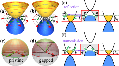
The band gap also significantly affects quasiparticle tunneling, which is associated with the pseudospin Katsnelson et al. (2006) and the Berry phase Varlet et al. (2014, 2016). The quasiparticle tunneling in pristine BLG exhibits perfect reflection when the charge carriers encounter a sharp potential barrier at normal incidence, effect known as anti-Klein tunneling Katsnelson et al. (2006); Kleptsyn et al. (2015), as illustrated in Fig. 1(e). However, when the band gap opens, anti-Klein tunneling can be reduced while the Berry phase slightly changes Varlet et al. (2014). Indeed perfect Klein tunneling, i.e., full transmission through a potential barrier Katsnelson et al. (2006); Katsnelson (2012); Shytov et al. (2008); Young and Kim (2009); Torres et al. (2014), may be possible in gapped BLG due to the out-of-plane polarization of the pseudospin Varlet et al. (2016) (see Fig. 1(f)). However, the observation of Klein tunneling in gapped BLG requires low-disorder devices and ballistic transport. To the best of our knowledge, such an anti-Klein to Klein tunneling transition has not been observed in BLG.
In this paper, we employ an edge-connected hBN-BLG-hBN heterostructure (hBN for hexagonal boron nitride) to investigate quasiparticle tunneling in a lateral junction. We benefit from an advanced sample fabrication method Wang et al. (2013), yielding ultra-clean devices, which enable ballistic Fabry-Pérot (FP) interferences Rickhaus et al. (2013). The phase-sensitive FP interference is used to detect the variation of the Berry phase. In contrast to previous work examining the Berry phase merely at high Fermi energies Varlet et al. (2014), the robust FP interference allows us to probe it close to the band edge. The role of the Berry phase and of the corresponding pseudospin on the quasiparticle tunneling will be discussed in detail and compared to numerical simulations based on a tight-binding model Liu et al. (2012).
Sample description.
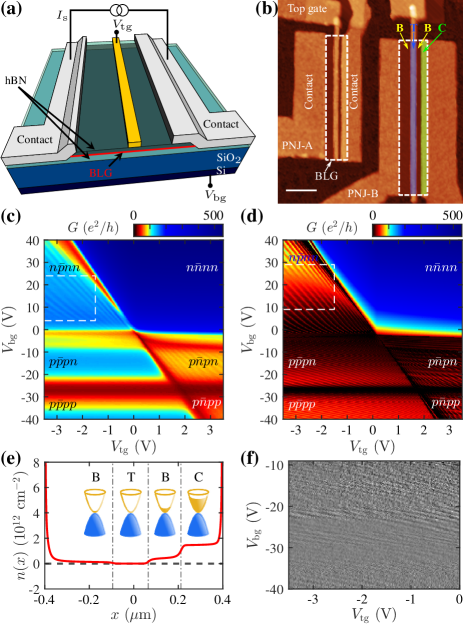
The investigated devices, sketched in Fig. 2(a), consist of a hBN-BLG-hBN heterostructure. The encapsulation of BLG results in low-disorder devices, allowing ballistic transport over a distance of . The potential profile across the device is controlled by a local top gate about wide as well as a global back gate (Si substrate). The fabrication follows Ref. Wang et al., 2013. Details of the devices are shown in Supplemental Material 111See Supplemental Material for full description of the sample information, electrostatic model, Fabry-Pérot interferences, the Berry phase and quasiparticle tunneling.. Each device is divided into four regions, labeled as T (top- and back-gated region), B (only back-gated regions), and C (contact-overlapping region) in Fig. 2(b). The overlapping contact results in additional -doping in region C when both gates are set to zero, as displayed in Fig. 2(e), where the carrier density profile is obtained from finite-element-based electrostatic simulation using FEniCS Logg et al. (2012) combined with the mesh generator Gmsh Geuzaine and Remacle (2009).
Fabry-Pérot interferences.
The conductance () as a function of the top- () and back-gate () voltages has been probed experimentally and modeled for device PNJ-A, as shown in Figs. 2(c) and (d), respectively. The conductance minima appear as three lines in these plots. The two horizontal lines at and are independent of , and indicate the charge neutrality point (CNP) in regions B and C, respectively. The position of the CNP is determined by the initial doping of each region (see Fig. 2(e)). The diagonal line shows the CNP of the dual-gated region T and defines the displacement field axis, along which the interlayer asymmetry develops. The three lines partition the map into six sections, each of which has a unique combination of charge carrier polarities, as labeled on Figs. 2(c)–(d).
FP interferences arise in an electrostatic potential barrier with two semi-transmitting interfaces, if the phase difference between two neighboring transmitted waves fits the resonance condition ( is integer). In the bipolar regime (, and ), where the charge carrier type in region T (denoted by the overlined symbol) is different from adjacent region B, we observe clear conductance oscillations as a consequence of FP interferences. The FP fringes extend along the diagonal line, illustrating that the FP interference occurs in a cavity tuned by both and . The cavity length is determined by the resonance condition of FP interferences as in Ref. Varlet et al., 2014, and is found to be around , which corresponds to the top-gate width. On the other hand, due to the long spacing between the contacts, FP interferences in unipolar regimes such as and are hardly visible. However, the weak oscillations become discernible in the transconductance gate map, see Fig. 2(f). More details about FP interferences are shown in Supplemental Material Note (1).
To gain further insight into the implications and ramifications of our experimental results, quantum transport simulations based on the real-space Green’s function method using the tight-binding model for Bernal-stacked BLG has been performed. Details of the simulation method are similar to Ref. Varlet et al., 2014, including how the gate-tunable interlayer asymmetry parameter can be implemented McCann and Koshino (2013), with the following two alterations. First, the scalable tight-binding model Liu et al. (2015) with a scaling factor of has been adopted. Second, carrier density profiles obtained from electrostatic simulations [an example is shown in Fig. 2(e)] have been implemented in order to extract realistic on-site energy profiles for the tight-binding model Hamiltonian. More details about the gate-modulated carrier density profiles can be found in Supplemental Material Note (1). Comparing Figs. 2(c) and (d), our experiment captures all the interference patterns that are theoretically predicted. This agreement demonstrates the high quality of both our FP interferometer design and the quantum transport simulations, even comparable to the suspended graphene interferometer with smooth junction profiles that led to high FP finesse Rickhaus et al. (2013).
Berry phase and quasiparticle tunneling.
At low magnetic fields, the phase difference comprises not only the conventional kinetic part, the Wentzel-Kramers-Brillouin phase , but also the Aharonov-Bohm phase and the Berry phase , which may arise under magnetic fields. The effect of the Berry phase on FP interferences may manifest itself as phase shifts of the FP fringes at certain magnetic fields Shytov et al. (2008); Young and Kim (2009); Varlet et al. (2014), unlike and yielding a continuous parabolic dispersion of the fringes with respect to Varlet et al. (2016). Thus, the phase-sensitive FP interference is a convenient tool to probe the Berry phase generated in the cavity.
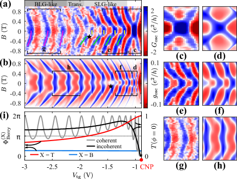
We observe the FP interference under low magnetic fields () by tuning at fixed , see Fig. 3(a). Here, the oscillatory part of the conductance is presented instead of the total conductance in order to circumvent the non-uniform conductance profile induced by the increasing magnetic field. We subtract a smoothed background at each value, and obtain the oscillatory part via . The low-field dispersion of the FP fringes shows two distinct features. For close to the CNP (), the FP fringes shift suddenly from the initial positions (e.g. yellow lines) to positions at slightly lower (e.g. green lines) at –, indicating that the Berry phase has been abruptly added to Young and Kim (2009); Shytov et al. (2008); Ramezani Masir et al. (2010); Liu and Richter (2012). The amount of phase shift for each fringe increases with decreasing , and reaches at (see the black star in Fig. 3(a)), suggesting that the Berry phase is continuously tuned across by modulating . Here, the emergence of the Berry phase at instead of , resembles the behavior of single-layer graphene (SLG), where the required geometric paths to acquire the Berry phase are formed with the assistance of low magnetic fields Young and Kim (2009); Shytov et al. (2008); Ramezani Masir et al. (2010); Liu and Richter (2012). For far away from the CNP (), the FP fringes exhibit parabolic dispersion (marked by magenta lines) with respect to as expected for BLG Varlet et al. (2014). This BLG-like dispersion without phase shift at illustrates that the Berry phase has already been included in at , highlighted by a transition region (labeled by Trans. in Fig. 3(a)) between the BLG-like and SLG-like dispersions. The reason is that the trajectory of the wave vector () forms a closed loop encircling the origin of momentum space, thus resulting in the non-zero Berry phase Varlet et al. (2016).
We have successfully reproduced the two types of dispersion, i.e., the SLG-like and the BLG-like, using quantum transport simulations based on a realistic electrostatic model, which is constructed from our experimental parameters but with a scattering region (the length ) around the top gate, see Fig. 3(b). Note that is the oscillatory part of the calculated single-mode conductance Liu et al. (2012); Rickhaus et al. (2013); Note (1), and obtained using the same procedure as . For better comparison, the fringes in the regions labeled by c–h are highlighted in Figs. 3(c)–(h). We found that the simulation result shows remarkable agreement with the experiment on the SLG-like (Figs. 3(e)–(f)) and BLG-like (Figs. 3(g)–(h)) dispersions under low magnetic fields, although the simulated patterns in Figs. 3(d), (f) and (h) occupy smaller regions in Fig. 3(b). In addition, the Berry phase of appears at (black star) in Fig. 3(b) instead of near due to the reasonable differences between the realistic electrostatic model and the intricate experiments.
We calculate the Berry phase by circular integral Varlet et al. (2014, 2016); Xiao et al. (2010) for the gate range in Fig. 3(a) (see Fig. 3(i)). The Berry phase in region T () is modulated from to while lowering , which well accounts for the phase shifts in Fig. 3(a). Particularly, the Berry phase in region T crosses at , which is consistent with the -shift position in Fig. 3(a). Besides, the Berry phase in region B () is only affected by and takes a constant value of for .
The quasiparticle tunneling in gapped BLG is simultaneously tuned as the Berry phase changes in T. Given the variation of , we expect a transition from anti-Klein tunneling, corresponding to the Berry phase of , to Klein tunneling, at the Berry phase , to reentrant anti-Klein tunneling upon further decreasing the Berry phase Varlet et al. (2016). To demonstrate the anticipated transitions, the transmission probability at normal incidence (see Fig. 3(i)) is investigated by quantum transport simulations for two cases: phase-coherent (grey curve) and phase-incoherent (black curve). The phase-coherent transmission probability oscillates due to the resonance condition. Instead, the phase-incoherent transmission probability suppresses the resonance and is calculated by the relation Datta (1997), where and represent the transmission probability through the left and right interfaces of the potential barrier, respectively. The resulting phase-incoherent agrees with our expectation except two differences. (i) The Berry phase for anti-Klein tunneling, , appears at the CNP, where zero charge carrier density in region T also gives rise to the inhibition of transmission as anti-Klein tunneling. (ii) The maximum reaches 0.87 at , which is close to the unity transmission probability for perfect Klein tunneling Katsnelson et al. (2006); Katsnelson (2012); Shytov et al. (2008); Young and Kim (2009). The factor that impedes the maximum to reach 1, is the Berry phase in region B, which is far from . But perfect Klein tunneling requires the Berry phase to be in both T and B regions. In addition, the reduction of for suggests that anti-Klein tunneling is partially restored. Therefore, the quasiparticle tunneling undergoes two processes: reaching Klein tunneling and recovering anti-Klein tunneling.
The transition from anti-Klein to Klein tunneling actually relies on the modulation of pseudospin orientation in gapped BLG. When the Fermi level is tuned close to the band edge, the pseudospin is rotated out of plane (see Fig. 1(b)), leading to the broken chirality Min et al. (2008); MacDonald et al. (2012); Lundeberg and Folk (2014); Varlet et al. (2016). The momentum of charge carriers is, therefore, unlocked to the pseudospin, allowing Klein tunneling in gapped BLG (see Fig. 1(f)). Even though the chirality sustains Klein tunneling in SLG Katsnelson et al. (2006); Katsnelson (2012), the contrary happens in gapped BLG, i.e., Klein tunneling favors the impaired chirality. On the other hand, the chirality can be restored in gapped BLG Varlet et al. (2016), as long as the pseudospin recovers its in-plane orientation at sufficiently high Fermi energies; at the same time, the Berry phase of (or equivalently ) as well as anti-Klein tunneling are regained. The recovery of anti-Klein tunneling is affected by two parameters, namely, the interlayer asymmetry and the Fermi energy. The chirality is broken because of the increasing interlayer asymmetry but recovered due to the rising Fermi energy.
SLG-like and BLG-like Berry phase.
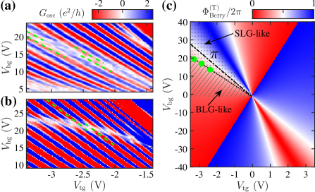
Figures 4(a) and (b) show the FP interference patterns magnified from the white rectangles in Figs. 2(c) and (d), respectively. Both experiments and simulation show nearly half-period shifts of the FP fringes, for example, highlighted by the green-dashed lines in Figs. 4(a) and (b). The nearly half-period shifts indicate that a phase change of about is suddenly incorporated in the phase difference . This phase shifts can be attributed to two different ways, i.e., the SLG-like and the BLG-like, to acquire the Berry phase in gapped BLG. For better interpretation, we calculate the Berry phase in region T as a function of and Varlet et al. (2014) (see Fig. 4(c)). The phase-shift positions in Fig. 4(a) are labeled as three green dots on Fig. 4(c), which arrange along the dotted line. The BLG-like can be acquired at zero magnetic field, hence, it appears as the predicted values in the striped-shade region of Fig. 4(c). However, the SLG-like needs low magnetic fields to develop, and is unavailable at . Actually, in the dotted-shade region remains zero instead of the calculated value. Accordingly, the phase shifts about show up around the intersection between the SLG-like and BLG-like regions, i.e., the dotted line, and directly prove the existence of two mechanisms, SLG-like and BLG-like, to obtain the Berry phase in gapped BLG.
Conclusion.
We have examined the quasiparticle tunneling as well as the related Berry phase in BLG using a Fabry-Pérot interferometer based on a dual-gated geometry. As the crystal inversion symmetry is broken by applying a displacement field, a full control of the Berry phase within the range – is achieved by manipulating the Fermi energy of charge carriers. Two distinct ways to acquire the Berry phase, SLG-like and BLG-like, coexist and can be switched between each other. Consequently, the corresponding quasiparticle tunneling undergoes a transition from anti-Klein to almost complete Klein tunneling with a maximum transmission probability of 0.87 at normal incidence. Therefore, in gapped BLG, tuning from BLG-like anti-Klein tunneling to SLG-like Klein tunneling is reachable by appropriate electrical gating.
Acknowledgements.
We acknowledge A. Varlet for fruitful discussions. Financial supports from the Deutsche Forschungsgemeinschaft (DFG) within SFB 689, project Ri 681-13/1 and the program of the Forschungsgroßgeräte 121384/17-1, the Helmholtz association through the program STN, as well as the DFG Center for Functional Nanostructures (CFN) are gratefully acknowledged.References
- Novoselov et al. (2005) K. S. Novoselov, A. K. Geim, S. V. Morozov, D. Jiang, M. I. Katsnelson, I. V. Grigorieva, S. V. Dubonos, and A. A. Firsov, Nature 438, 197 (2005).
- Geim and Novoselov (2007) A. K. Geim and K. S. Novoselov, Nat. Mater. 6, 183 (2007).
- Castro Neto et al. (2009) A. H. Castro Neto, F. Guinea, N. M. R. Peres, K. S. Novoselov, and A. K. Geim, Rev. Mod. Phys. 81, 109 (2009).
- Liu et al. (2011) Y. Liu, G. Bian, T. Miller, and T.-C. Chiang, Phys. Rev. Lett. 107, 166803 (2011).
- Morozov et al. (2008) S. V. Morozov, K. S. Novoselov, M. I. Katsnelson, F. Schedin, D. C. Elias, J. A. Jaszczak, and A. K. Geim, Phys. Rev. Lett. 100, 016602 (2008).
- Novoselov et al. (2006) K. S. Novoselov, E. McCann, S. V. Morozov, V. I. Fal’ko, M. I. Katsnelson, U. Zeitler, D. Jiang, F. Schedin, and A. K. Geim, Nat. Phys. 2, 177 (2006).
- McCann (2006) E. McCann, Phys. Rev. B 74, 161403 (2006).
- McCann and Koshino (2013) E. McCann and M. Koshino, Rep. Prog. Phys. 76, 056503 (2013).
- Oostinga et al. (2008) J. B. Oostinga, H. B. Heersche, X. Liu, A. F. Morpurgo, and L. M. K. Vandersypen, Nat. Mater. 7, 151 (2008).
- Zhang et al. (2009) Y. Zhang, T.-T. Tang, C. Girit, Z. Hao, M. C. Martin, A. Zettl, M. F. Crommie, Y. R. Shen, and F. Wang, Nature 459, 820 (2009).
- Taychatanapat and Jarillo-Herrero (2010) T. Taychatanapat and P. Jarillo-Herrero, Phys. Rev. Lett. 105, 166601 (2010).
- Berry (1984) M. V. Berry, P. Roy. Soc. Lond. A Mat. 392, 45 (1984).
- Zhang et al. (2005) Y. Zhang, Y.-W. Tan, H. L. Stormer, and P. Kim, Nature 438, 201 (2005).
- Varlet et al. (2014) A. Varlet, M.-H. Liu, V. Krueckl, D. Bischoff, P. Simonet, K. Watanabe, T. Taniguchi, K. Richter, K. Ensslin, and T. Ihn, Phys. Rev. Lett. 113, 116601 (2014).
- Varlet et al. (2016) A. Varlet, M.-H. Liu, D. Bischoff, P. Simonet, T. Taniguchi, K. Watanabe, K. Richter, T. Ihn, and K. Ensslin, Phys. Status Solidi RRL 10, 46 (2016).
- Katsnelson et al. (2006) M. I. Katsnelson, K. S. Novoselov, and A. K. Geim, Nat. Phys. 2, 620 (2006).
- Katsnelson (2012) M. I. Katsnelson, Graphene: Carbon in Two Dimensions (Cambridge University Press, 2012).
- Kleptsyn et al. (2015) V. Kleptsyn, A. Okunev, I. Schurov, D. Zubov, and M. I. Katsnelson, Phys. Rev. B 92, 165407 (2015).
- Min et al. (2008) H. Min, G. Borghi, M. Polini, and A. H. MacDonald, Phys. Rev. B 77, 041407 (2008).
- MacDonald et al. (2012) A. H. MacDonald, J. Jung, and F. Zhang, Phys. Scripta 2012, 014012 (2012).
- Xiao et al. (2010) D. Xiao, M. C. Chang, and Q. Niu, Rev. Mod. Phys. 82, 1959 (2010).
- Lundeberg and Folk (2014) M. B. Lundeberg and J. A. Folk, Science 346, 422 (2014).
- Ghahari et al. (2017) F. Ghahari, D. Walkup, C. Gutiérrez, J. F. Rodriguez-Nieva, Y. Zhao, J. Wyrick, F. D. Natterer, W. G. Cullen, K. Watanabe, T. Taniguchi, L. S. Levitov, N. B. Zhitenev, and J. A. Stroscio, Science 356, 845 (2017).
- San-Jose et al. (2009) P. San-Jose, E. Prada, E. McCann, and H. Schomerus, Phys. Rev. Lett. 102, 247204 (2009).
- Xiao et al. (2007) D. Xiao, W. Yao, and Q. Niu, Phys. Rev. Lett. 99, 236809 (2007).
- Yao et al. (2008) W. Yao, D. Xiao, and Q. Niu, Phys. Rev. B 77, 235406 (2008).
- Gorbachev et al. (2014) R. V. Gorbachev, J. C. W. Song, G. L. Yu, A. V. Kretinin, F. Withers, Y. Cao, A. Mishchenko, I. V. Grigorieva, K. S. Novoselov, L. S. Levitov, and A. K. Geim, Science 346, 448 (2014).
- Shimazaki et al. (2015) Y. Shimazaki, M. Yamamoto, I. V. Borzenets, K. Watanabe, T. Taniguchi, and S. Tarucha, Nat. Phys. 11, 1032 (2015).
- Nagaosa et al. (2010) N. Nagaosa, J. Sinova, S. Onoda, A. H. MacDonald, and N. P. Ong, Rev. Mod. Phys. 82, 1539 (2010).
- Qiao et al. (2014) Z. Qiao, W. Ren, H. Chen, L. Bellaiche, Z. Zhang, A. H. MacDonald, and Q. Niu, Phys. Rev. Lett. 112, 116404 (2014).
- Shytov et al. (2008) A. V. Shytov, M. S. Rudner, and L. S. Levitov, Phys. Rev. Lett. 101, 156804 (2008).
- Young and Kim (2009) A. F. Young and P. Kim, Nat. Phys. 5, 222 (2009).
- Torres et al. (2014) L. E. F. F. Torres, S. Roche, and J. C. Charlier, Introduction to Graphene-Based Nanomaterials: From Electronic Structure to Quantum Transport (Cambridge University Press, 2014).
- Wang et al. (2013) L. Wang, I. Meric, P. Y. Huang, Q. Gao, Y. Gao, H. Tran, T. Taniguchi, K. Watanabe, L. M. Campos, D. A. Muller, J. Guo, P. Kim, J. Hone, K. L. Shepard, and C. R. Dean, Science 342, 614 (2013).
- Rickhaus et al. (2013) P. Rickhaus, R. Maurand, M.-H. Liu, M. Weiss, K. Richter, and C. Schönenberger, Nat. Commun. 4, 2342 (2013).
- Liu et al. (2012) M.-H. Liu, J. Bundesmann, and K. Richter, Phys. Rev. B 85, 085406 (2012).
- Note (1) See Supplemental Material for full description of the sample information, electrostatic model, Fabry-Pérot interferences, the Berry phase and quasiparticle tunneling.
- Logg et al. (2012) A. Logg, K.-A. Mardal, and G. N. Wells, Automated Solution of Differential Equations by the Finite Element Method (Springer, 2012).
- Geuzaine and Remacle (2009) C. Geuzaine and J.-F. Remacle, Int. J. Numer. Meth. Eng. 79, 1309 (2009).
- Liu et al. (2015) M.-H. Liu, P. Rickhaus, P. Makk, E. Tóvári, R. Maurand, F. Tkatschenko, M. Weiss, C. Schönenberger, and K. Richter, Phys. Rev. Lett. 114, 036601 (2015).
- Ramezani Masir et al. (2010) M. Ramezani Masir, P. Vasilopoulos, and F. M. Peeters, Phys. Rev. B 82, 115417 (2010).
- Liu and Richter (2012) M.-H. Liu and K. Richter, Phys. Rev. B 86, 115455 (2012).
- Datta (1997) S. Datta, Electronic Transport in Mesoscopic Systems (Cambridge University Press, 1997).