Scatter Radio Receivers for Extended Range Environmental Sensing WSNs
Abstract
Backscatter communication, relying on the reflection principle, constitutes a promising-enabling technology for low-cost, large-scale, ubiquitous sensor networking. This work makes an overview of the state-of-the-art coherent and noncoherent scatter radio receivers that account for the peculiar signal model consisting of several microwave and communication parameters.
I Introduction
The need of ubiquitous environmental sensing has lead to the adoption of cost-effective, large-scale wireless sensor networks (WSNs). Such networks consists of several low-power and low-cost devices that sense environmental variables (such as soil humidity, soil moisture, temperature) and gathering the sensed information at a central unit. Existing commercial WSN equipment incorporates devices consisting of complex active radio frequency (RF) components that increase significantly the total monetary cost, as well as the overall energy consumption per sensor node.
Scatter radio adopts the reflection principle [1], which is achieved by generating a carrier wave that illuminates a set of RF tag/sensors. A RF tag terminates its antenna load according to the data to be transmitted. The incident signal is modulated and scattered back towards a software-defined radio (SDR) reader for processing. The above idea is depicted in Fig. 1.
This work proposes bistatic scatter radio technology with semi-passive tags and frequency shift-keying (FSK) modulation, ideal for the power limited regime [2]. The specific three-fold design mixture, not only reduces the energy cost per sensor tag, but also does not sacrifice in total communication range, achieving ranges on the order of a hundred of meters, as opposed to the conventional passive radio frequency identification (RFID) Gen 2 architecture that offers a limited range on the order of very few meters. A thorough overview of the state-of-the-art coherent and noncoherent scatter radio FSK receivers is subsequently conducted. The receivers are capable to achieve one hundred and fifty meters communication range.
II Bistatic Scatter Radio Signal Model
The bistatic scatter radio architecture is employed, consisting of a carrier emitter, a RF tag, and a software-defined radio (SDR) reader (Fig. 1). Due to the relatively small bit-rate (on the order of few kilobits per second), along with the fact that the carrier emitter-to-SDR reader and tag-to-SDR reader links are on the order of a kilometer, i.e., small delay spread, frequency non-selective (flat) fading channel is assumed, where the baseband complex channel response for a duration of channel coherence time, , is given by where denote the channel attenuation parameters of the corresponding links and stand for the respective phases due to signal propagation delay, all independent of each other. Parameters are assumed Rician distributed due to strong line-of-site signals, commonly encountered in outdoors WSNs.

Carrier emitter transmits a continuous sinusoid wave at carrier frequency that illuminates the tag. Tag modulates the received signal at passband using duty cycle square waveform pulse of frequency and random initial phase and backscatters it towards SDR reader. The received complex baseband signal at the SDR reader is given by the superposition of the carrier emitter sinusoid and the backscattered tag signal through channels and , respectively. The received signal also suffers from band-limited noise with power spectral density over SDR receiver bandwidth . SDR reader applies carrier frequency offset (CFO) estimation and compensation using periodogram-based techniques, DC blocking, and synchronization.
For and the noise-free, CFO-free, DC-blocked, and perfect synchronized baseband signal belongs to a four dimensional, time limited in signal space, whose orthonormal basis is denoted as , where is the square waveform of duration . The optimal demodulator projects received signal on basis through correlators and the discrete baseband signal over bit duration can be written as [3]
| (1) |
where incorporates the fading coefficients as well as the phase difference of compound link carrier emitter-to-tag-to-SDR reader. is the average energy per bit in baseband, is the four-dimensional symbol corresponding to bit , and
III Bistatic Scatter Radio FSK Receivers
III-A Uncoded Reception
III-A1 Coherent Detector [3]
The coherent receiver estimates the compound channel through the use of training symbols. After obtaining the least-squares estimate of compound channel , , the maximum-likelihood (ML) detector is applied through the rule [3]
| (2) |
III-A2 Noncoherent Detectors [4]
The first symbol-by-symbol noncoherent detector treats the parameter as deterministic and parameters as random; it is called hybrid composite hypothesis testing (HCHT) detector and is given by [5]
| (3) | ||||
| (4) |
The second symbol-by-symbol detector is the generalized-likelihood ratio test (GLRT) detector, that treats all unknown parameters as deterministic and is expressed as [4]
| (5) | ||||
| (6) |
For a bit sequence of bits satisfying , the received sequence a can be written as with with , . To reduce the sequence error rate, a noncoherent sequence detector may be applied. For the above signal model, the GLRT sequence detector is expressed as
| (7) |
Work in [4] partitions the space of phases in distinct points and solves the above problem with complexity using the same procedure with the work in [6].
III-B Coded Reception
When channel coding is utilized, the transmitter encodes a sequence of bits to a sequence of coded bits, belonging to a code .
III-B1 Coherent Decoder [3]
III-B2 Nonoherent Decoder [4]
Suppose that we employ channel coding, noncoherent receiver, and the use of interleaving technique of interleaving depth satisfying ; accordingly with Eq. (3), HCHT decoder can be derived as [5]
| (9) |
For the case of , the above decoder is suboptimal, however, it is utilized for any value of , due to its inherent simplicity.
IV Simulation Results
Simulations are conducted for bistatic scatter radio system model assuming backscatter FSK transmissions with bit rate msec, over quasi-static Rician flat fading channel with coherence time msec. In all simulation results we have assumed perfect synchronization, perfect CFO estimation/compensation, and fixed energy budget per transmitted packet for all schemes.
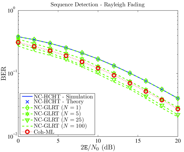
Fig. 2 illustrates the bit error rate (BER) performance of all uncoded schemes studied in Section III-A as function of average received signal-to-noise ratio, . We observe that GLRT sequence detector outperforms all schemes. It is also noted that coherent ML detector offers 3dB better BER performance compared to noncoherent symbol-by-symbol schemes.
References
- [1] H. Stockman, “Communication by means of reflected power,” Proc. IRE, pp. 1196–1204, 1948.
- [2] J. Kimionis, A. Bletsas, and J. N. Sahalos, “Increased range bistatic scatter radio,” IEEE Trans. Commun., vol. 62, no. 3, pp. 1091–1104, Mar. 2014.
- [3] N. Fasarakis-Hilliard, P. N. Alevizos, and A. Bletsas, “Coherent detection and channel coding for bistatic scatter radio sensor networking,” IEEE Trans. Commun., vol. 63, no. 5, pp. 1798–1810, May 2015.
- [4] P. Alevizos, A. Bletsas, and G. N. Karystinos, “Noncoherent short packet detection and decoding for scatter radio sensor networking,” IEEE Trans. Commun., 2017, to appear.
- [5] P. N. Alevizos and A. Bletsas, “Noncoherent composite hypothesis testing receivers for extended range bistatic scatter radio WSNs,” in Proc. IEEE Int. Conf. on Commun. (ICC), London, UK, Jun. 2015.
- [6] P. N. Alevizos, Y. Fountzoulas, G. N. Karystinos, and A. Bletsas, “Log-linear-complexity GLRT-optimal noncoherent sequence detection for orthogonal and RFID-oriented modulations,” IEEE Trans. Commun., 2016, to appear.