The Unheralded Value of the Multiway Rendezvous: Illustration with the Production Cell Benchmark
Abstract
The multiway rendezvous introduced in Theoretical CSP is a powerful paradigm to achieve synchronization and communication among a group of (possibly more than two) processes. We illustrate the advantages of this paradigm on the production cell benchmark, a model of a real metal processing plant, for which we propose a compositional software controller, which is written in LNT and LOTOS, and makes intensive use of the multiway rendezvous.
1 Introduction
We investigate the design of software controllers for complex systems. Concurrency is a natural way to specify such controllers by decomposing their software into separate processes, each dedicated to a specific activity or a specific aspect of the system. For instance, an automatic pilot may include two concurrent processes that control roll and pitch, respectively; also, a controller for a robot operating in a space with degrees of freedom may contain processes, each supervising the robot motion within a given degree of freedom.
Concurrency is a high-level specification paradigm that can be implemented in diverse ways. On the one hand, implementations can be done in hardware, in software, or in a combination of both. On the other hand, implementations may either preserve the concurrency present at the specification level by translating it into parallel code, or remove concurrency by expanding/flattening it into sequential code.
Whatever implementation techniques are chosen, the different processes that constitute a controller, even if they can be independent to a large degree, must also synchronize, communicate, and co-operate to achieve common goals and enforce global constraints applying to the system. Among the various paradigms proposed for synchronization and communication, the multiway rendezvous designed for Theoretical CSP [12] [46] [65] presents major advantages, although these are not always perceived or put forward.
In this article, we illustrate the merits of the multiway rendezvous on a benchmark that once enjoyed a large visibility among the formal methods community: the production cell case study [57]. For this benchmark, we developed a software controller, which makes intensive use of the multiway rendezvous and enjoys a nicely distributed architecture. This controller was first designed in LOTOS [50], then in LNT [18]. The full code of the LNT specification, which is easier to read, is given in Appendix C, but most of the discussion applies to both LOTOS and LNT.
The remainder of this article is organized as follows. Section 2 recalls the principles and benefits of the multiway rendezvous. Section 3 describes the production cell case study, an overview of formal specifications already developed for this benchmark being given in Appendix A. Section 4 presents the principles and the architecture of our LOTOS and LNT specifications. Section 5 details how controller implementations can be generated automatically from these specifications and Section 6 discussses validation issues. Finally, Section 7 gives a few concluding remarks.
2 The Multiway Rendezvous
From an historical point of view, the multiway rendezvous is not a concept designed in one day, but rather the result of a long evolution alternating major shifts and incremental improvements:
-
•
From the origins to the mid-70s, interprocess communication was mostly achieved using shared variables, whereas synchronization between concurrent processes relied upon memory-based mechanisms (semaphores, locks, critical sections, etc.). Such approaches had several drawbacks: lack of abstraction, existence of multiple incompatible semantics, difficulty to design correct programs, and difficulty for automated tools to analyze processes in which variables can be modified by other processes at any time.
-
•
In 1978, C.A.R. Hoare introduced CSP [45], a language built around the concept of rendezvous, a new message-passing paradigm unifying synchronization and communication. A key advantage of this paradigm is that the few places where a variable can be modified by a concurrent process are explicitly documented. In CSP, a rendezvous can only take place between two processes (a sender and a receiver) and the parallel architecture is “hard-coded”, as each process must explicitly indicate, at each rendezvous point, the name of the concurrent process it communicates with.
-
•
In 1980, R. Milner proposed CCS [61], a language that reuses the concept of binary rendezvous, for which he defined a formal semantics. CCS solves the aforementioned issue with CSP by introducing the concept of port that allows for reusable process components and parameterized parallel architectures. In CCS, processes no longer refer directly to other processes but only indirectly, using ports, which are intermediate communication objects that connect processes together.
-
•
In 1984, S.D. Brookes, C.A.R. Hoare, and A.W. Roscoe designed a refined version of CSP named TCSP (Theoretical CSP) [12] [46], which combines ideas from CSP and CCS. A major innovation brought by TCSP is the multiway rendezvous, which generalizes binary rendezvous to more than two processes. A formal semantics (given in terms of traces and refusals) takes care of the presence of multiple senders and/or receivers.
-
•
At the same time, an ISO standardization committee headed by E. Brinksma had undertaken the definition of LOTOS, a new formal language to describe communication protocols. The committee initially selected the binary rendezvous of CCS, until A.J. Tocher presented the TCSP multiway rendezvous, which was adopted and included in the standard [50]. LOTOS brought useful features, such as multiple value parameters, strict type checking, and the extension of selection predicates (i.e., Boolean guards that forbid rendezvous if they evaluate to false) to multiway rendezvous.
In our opinion, multiway rendezvous is one of the best features of LOTOS, while none of the two other standards, Estelle [49] and SDL [17] that competed with LOTOS at those times, provided a similar expressiveness. It is therefore no surprise that multiway rendezvous has been preserved in the next-generation languages based on LOTOS, namely E-LOTOS [51] and LNT [18], as well as in the FDR2 [27] implementation of TCSP.
-
•
In 1999, H. Garavel and M. Sighireanu proposed “graphical” parallel composition operators [35], which take arguments (whereas the traditional parallel composition operators accept only two arguments) and are thus better in line with the concept of multiway rendezvous. These operators have been implemented in LNT and are used in Appendix C of the present article.
Beyond these languages, the multiway rendezvous paradigm has not spread as largely as one would wish. One reason for this is the influence of CCS, which promotes an incompatible paradigm of binary-only communication. Another reason is the high difficulty to properly implement multiway rendezvous, either in a sequential setting or in a distributed setting; for the latter point, which is even more difficult, let us mention recent work that implements the LOTOS multiway rendezvous among a collection of distributed processes interconnected by POSIX sockets [26] [25] [24]. However, concepts similar or close to the multiway rendezvous are indeed present in certain computer languages or models:
-
•
The mCRL2 process algebra [39] also contains multiway synchronization. Compared to LOTOS and CSP, the main difference is that mCRL2 actions are “output-only” (at least syntactically), because mCRL2 does not feature the CSP notations for inputs and outputs: “?” is absent and “!” is implicit — see [30, Section 3.3] for details.
-
•
Petri nets can naturally express multiway synchronization between processes by means of transitions having input places and output places. The CÆSAR compiler [34], which translates LOTOS terms to interpreted Petri nets, uses this Petri-net feature to implement LOTOS multiway rendezvous.
-
•
Barriers are lower-level mechanisms to collectively synchronize a set of processes or threads. The multiway rendezvous can be seen as a powerful generalization of barriers with: (i) data exchange capabilities taking place when all the processes/threads have reached the barrier, and (ii) the possibility for a process to choose between different barriers.
-
•
Synchronous languages also possess related concepts. For instance, Esterel [6] [63] can synchronize actions and compose together the values carried by each of these actions. To a certain extent, the multiway rendezvous imports synchronous concepts into an asynchronous setting: one can indeed use the multiway rendezvous to force a set of concurrent processes to synchronize, and possibly exchange values at every tick of some logical clock.
In spite of the implementation difficulties, the multiway rendezvous remains a natural way to express synchronization among a set of distributed processes, as well as an irreplaceable mechanism to describe certain situations that, even if less frequent than binary communication, are not uncommon. Four examples of such situations are:
-
•
Observers: It is often useful to monitor data exchanges between two communicating processes. For instance, one may wish to count the number of messages exchanged between these processes or to build the list of such messages. This is not easy in languages that rely on binary communication, and even impossible in the case of CCS, where the synchronization of an emission and a reception is immediately turned into a (i.e., invisible or almost invisible) action. On the contrary, multiway rendezvous makes it easy to introduce a third “observer” process that also synchronizes on the communication action using a three-party rendezvous, without perturbing the two other processes.
-
•
Supervisors: A step beyond observers is to introduce a third “supervisor” process that not only observes communications passively, but also actively interferes by allowing or blocking certain communications, depending on the communication contents and/or the internal state of the supervisor process. For instance, a supervisor process may serialize actions by forcing them to occur in a specified order. This is easy to achieve using multiway synchronization, as a rendezvous can only take place when all participants (including the supervisor) agree.
An extended form of supervision is the constraint-oriented specification style [69] [70], in which each process imposes its specific constraints over exchanged data values or action order. Putting all these processes in parallel using multiway rendezvous amounts to taking the logical conjunction of all the constraints expressed by these processes. The execution of such a parallel composition behaves like a constraint solver that searches for possible solutions, if any.
-
•
Consensus: The multiway rendezvous between processes is a powerful abstraction that achieves, in a single atomic operation, a distributed consensus protocol. Describing the same protocol using binary communications is likely to cause an exponential blow-up, as all possible interleavings between the actions of the processes may occur. A salient example can be found in [31, Section 3], where multiway rendezvous is used to model the arbitration mechanism of the SCSI-2 hardware bus. In this example, an eight-party rendezvous expresses, in one atomic action: (i) a voting procedure in which each hardware device declares whether it wants to access the bus or not; (ii) the selection, among all devices requesting access, of the device with the lowest number; and (iii) the notification to each device whether it was granted access or not.
-
•
Coordination: In the present article, we illustrate yet another application of the multiway rendezvous. Given a software controller for a system evolving in a space with degrees of freedom, each degree being managed by a separate concurrent process in the controller, we use the multiway rendezvous to express high-level coordination goals between these processes, such as moving from a starting point to a target point . Each process is responsible for moving along one axis; depending on their respective speed, the various processes may reach their target in a nondeterministic order. Therefore, point is only reached when all processes have individually reached their target, which is conveniently expressed by a multiway rendezvous between synchronizing the processes. As a side remark, we only use the synchronization capabilities of the multiway rendezvous, as the problem requires no exchange of values when multiway rendezvous take place.
3 The Production Cell Case Study
The case study “Control Software for an Industrial Production Cell” [54] [56] was proposed in the 90s as a benchmark to assess the benefits of different formal methods applied to a common critical software system. The task description [59] required to use a formal method to develop a software controller for a production cell, replicating a real metal processing plant in Karlsruhe, Germany. The benchmark became popular and, in 1995, a book devoted to the production cell case study was published [57].
3.1 Overview of the Production Cell
The production cell operates on metal plates (or blanks), which are brought into the cell by a feed belt, transported to a press via an elevating rotary table and a two-armed robot, before they leave the cell on the deposit belt. Diverging from the concrete production cell and to obtain a cyclic behaviour, the blanks are transported by a crane from the deposit back to the feed belt.
The production cell is controlled by thirteen actuators , …, (motors and magnets) and is equipped with fourteen sensors , …, (switches, potentiometers, and photoelectric cells) to deliver status information to the controller.
3.2 The Graphical Simulator of the Production Cell
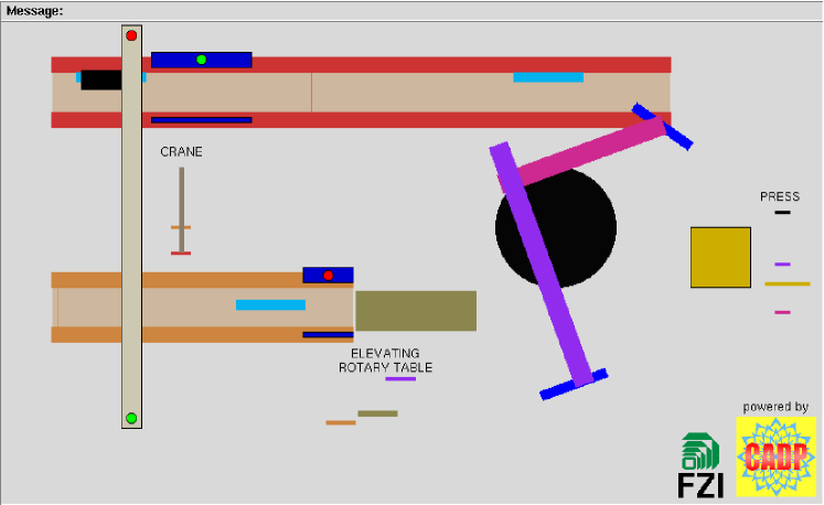
A graphical simulator [10] [11], written in Tcl/Tk, enables prototype controllers to be validated and provides a reference to compare the controllers obtained from executable formal methods. Unfortunately, the Tcl/Tk source code of this simulator is no longer available today, as the FTP server ftp.fzi.de hosting the original version of the simulator does not seem to respond any more. Luckily, a copy of the simulator was archived at INRIA Grenoble, improved in a few points, and regularly adapted to the latest versions of Tcl/Tk and operating systems (Linux, MacOS, Windows, etc.). A screenshot of this simulator is shown in Figure 1.
The simulator has two functioning modes: asynchronous or synchronous. In principle, the asynchronous mode, which is event-driven, should be more efficient, as the production cell controller does not poll periodically the sensors and, thus, avoids busy-waiting loops (i.e., reading the value of sensors when this is not necessary). Alas, the new_guard command, which allows actions to be triggered when certain conditions (depending on sensor values) become true, does not seem to function, and its usage is discouraged by the authors of the simulator [11, Section A.5.9].
Therefore, the synchronous mode, which is is cycle-driven, remains the only available option. This mode is activated via the command-line option -snc and achieves bidirectional communication between the simulator and its controller via a simple protocol based on character-string commands and replies. In this mode, the production cell controller is expected to perform an infinite loop of successive reaction steps, i.e., periodically: (i) acquire the current values of all sensors by sending a get_status command to the simulator; (ii) compute the appropriate reaction; (iii) send a sequence of commands to the actuators (at most one command per actuator); and (iv) terminate the current reaction step by sending a react command that instructs the simulator to update its state by executing all received actuator commands.
3.3 Prior Work on the Production Cell
The literature about the production cell case study is abundant. The reference book [57] describes the application of 18 different formal methods to the production cell case study. It then provides a brief comparative survey of these experiments [55] [56]. Since then, further experiments with other formal methods have been published separately. Some approaches also extend the original task description, e.g., [72] which investigates fault-tolerance, and [37], which considers a production cell with two presses.
In total, nearly 28 different formal methods have been applied to the production cell case study. Appendix A of the present article gives two overview tables providing bibliographic references. Unfortunately, most of the source specifications are no longer available, so that it is difficult to discuss their characteristics in detail and make a precise comparison between them.
Because the production cell benchmark comes with a graphical simulator, it clearly calls for executable formal methods, i.e., those from which executable code can be generated automatically and connected to the simulator. However, only five prior experiments with executable formal methods can be found in the literature, with three out of five experiments being done with synchronous languages (see Table 4 in Appendix A).
The present article rather explores the asynchronous side of executable formal methods. Although several approaches have specified the production cell controller as a set of distributed processes combined using rendezvous [64] or alternative synchronization primitives, such as interface functions [9] or coordinated atomic actions [73], there was no automatic code generation from these models. And, as far as we are aware, no prior approach uses multiway rendezvous.
4 The LOTOS and LNT Specifications of the Production Cell Controller
An early LOTOS specification of a controller for the production cell was developed in July 1994 by the first author, and revised in August 1994 to produce a second version taking advantage of the multiway rendezvous and enabled the automatic generation of controller implementation in C. Although there was a kind offer to submit this specification for publication in the reference book [57], there were still technical problems in connecting the controller to the graphical simulator, so that the LOTOS chapter for the book was left unfinished, the LOTOS specification being only mentioned in the comparative survey that forms Chapter 3 of the book [55]. The matter was put aside until 1997, where a fully functional version with an operational connection to the simulator was achieved with the help of Mark Jorgensen and integrated as a demonstration example111ftp://ftp.inrialpes.fr/pub/vasy/demos/demo19 to the CADP toolbox. In 2013, the specification was translated to LNT, mostly by the second author, who also simplified the LOTOS specification and improved its runtime performance. Both specifications have been further enhanced in 2017 when preparing the present article. The latest version of the LNT specification is provided in Appendix C.
4.1 Architectural Decomposition of the Controller
We first present the principles underlying the production cell controller in LOTOS and LNT. Rather than having a monolithic controller (which, because of its complexity, could not easily evolve if the production cell was modified or reorganized), it is desirable to design the controller in a modular way, by assembling simpler components together.
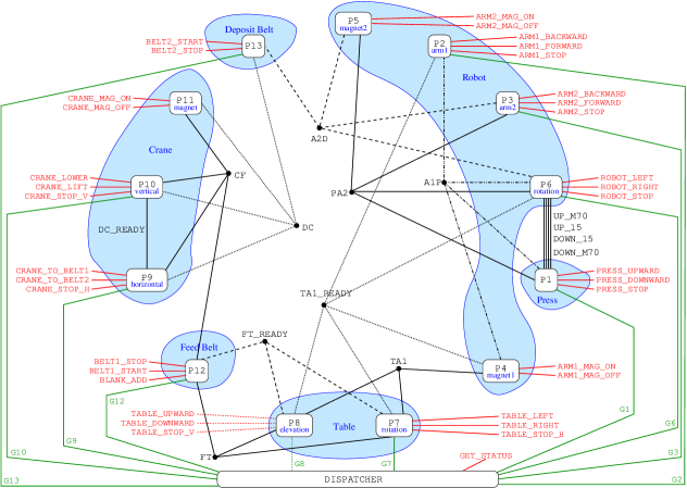
The most natural way to decompose the controller is to follow the topology of the production cell, whose different devices (feed belt, rotary table, robot, deposit belt, crane) form a logical ring in which each device has to watch for its neighbours, with the additional fact that the robot and the press must communicate with each other. The overall architecture of the controller is illustrated in Figure 2.
More precisely, we choose to manage each separately controllable device (or degree of freedom of a device) of the production cell by a dedicated process. The controller can thus be decomposed into 13 concurrent processes P1, …, P13, each process being in charge of the corresponding actuator (see Table 1 — the indices of actuators are those given in [59] and [11]).
| process | role |
|---|---|
| P1 | move the lower part of the press vertically |
| P2 | extend or retract the first robot arm |
| P3 | extend or retract the second robot arm |
| P4 | pick up or drop a metal plate with the first robot arm |
| P5 | pick up or drop a metal plate with the second robot arm |
| P6 | rotate the robot |
| P7 | rotate the rotary table |
| P8 | move the rotary table vertically |
| P9 | move gripper of the travelling crane horizontally |
| P10 | move gripper of the travelling crane vertically |
| P11 | pick up or drop a metal plate with crane’s gripper |
| P12 | start or stop the motor of the feed belt |
| P13 | start or stop the motor of the deposit belt |
Parallel composition is the natural way to express that the processes are largely independent from each other. Our controller is thus designed as a set of LOTOS and LNT processes that execute simultaneously and synchronize by rendezvous to coordinate those movements involving several devices.
To each of the 34 protocol commands sent to actuators (e.g., press_upward, press_stop, etc.), we associate a corresponding LOTOS or LNT gate (named PRESS_UPWARD, PRESS_STOP, etc.) and we divide these gates into 13 groups numbered from 1 to 13, such that group contains the gates related to actuator [59, Section 2.2.1]. The gate BLANK_ADD (corresponding to the command blank_add) is added to group 12 (feed belt) because new metal blanks are inserted into the production cell via the feed belt. Each process is responsible for accessing the gates of group and no other process can access these gates. Table 2 lists the gates in each group.
| group | gates | actuator |
|---|---|---|
| 1 | PRESS_UPWARD, PRESS_STOP, PRESS_DOWNWARD | press |
| 2 | ARM1_FORWARD, ARM1_STOP, ARM1_BACKWARD | extension of arm 1 |
| 3 | ARM2_FORWARD, ARM2_STOP, ARM2_BACKWARD | extension of arm 2 |
| 4 | ARM1_MAG_ON, ARM1_MAG_OFF | magnet of arm 1 |
| 5 | ARM2_MAG_ON, ARM2_MAG_OFF | magnet of arm 2 |
| 6 | ROBOT_LEFT, ROBOT_STOP, ROBOT_RIGHT | robot rotation |
| 7 | TABLE_LEFT, TABLE_STOP_H, TABLE_RIGHT | table rotation |
| 8 | TABLE_UPWARD, TABLE_STOP_V, TABLE_DOWNWARD | table elevation |
| 9 | CRANE_TO_BELT2, CRANE_STOP_H, CRANE_TO_BELT1 | move crane horizontally |
| 10 | CRANE_LIFT, CRANE_STOP_V, CRANE_LOWER | move crane vertically |
| 11 | CRANE_MAG_ON, CRANE_MAG_OFF | crane’s magnet |
| 12 | BELT1_START, BELT1_STOP, BLANK_ADD | feed belt |
| 13 | BELT2_START, BELT2_STOP | deposit belt |
Notice that the actuators commands could have been modelled differently by defining, rather than 35 gates without offer, only 13 gates (one per actuator) with output offers, i.e., values of enumerated types specifying the kind of movement expected (e.g., UPWARD, STOP, DOWNWARD, etc.). This solution was discarded because the previous one was simpler.
The processes also have to synchronize together, and their interactions are dictated by the topology of the production cell. To achieve such synchronizations, the LOTOS and LNT specifications introduce 14 dedicated gates (named FT_READY, FT, TA1_READY, TA1, A1P, PA2, etc.) that remain internal to the controller. For instance, gate PA2 expresses the (instantaneous) transfer of a blank from the press to the second arm of the robot. Other interactions are not instantaneous, so that processes need to synchronize at the beginning and at the end of the transfer; in such cases, two different gates are used. For instance, to transfer a blank from the feed belt to the table, the motor of the feed belt must be stopped when the blank arrives at its end (to avoid dropping the blank) until the table is correctly positioned (rendezvous on gate FT_READY) to receive the blank; then, the table must not move until the feed belt has been restarted (rendezvous on gate FT).
In a few cases, rendezvous on these gates involve two processes only (e.g., P9 and P10 synchronize on gate DC_READY) but, usually, multiway rendezvous between three, four, or five processes is needed. For instance, a three-party rendezvous on gate FT takes place when there is a blank at the end of the feed belt and the motor of the feed belt has been started (P12), and when the table is in a position (P7 and P8) where it can receive a blank from the feed belt. A four-party rendezvous on gate PA2 takes place when a blank is transferred from the press to the second arm of the robot and involves the process controlling the press (P1) and three processes controlling the robot for rotation (P6), extension of second arm (P3), and magnet of second arm (P5). A five-party rendezvous on gate TA1_READY takes place when the table is ready to deliver a blank element to the first arm of the robot and involves the two processes controlling the table (P7 and P8), the two processes controlling the first arm of the robot (P2 and P4), and the process controlling the rotation of the robot (P6).
To interface this fully asynchronous controller with the simulator in synchronous mode, an additional DISPATCHER process was added, which acquires sensor values using an externally visible gate GATE_STATUS (corresponding to the get_status protocol command [11]). Contrary to the commands for actuators, which can be emitted independently in any order, the sensor values must be acquired altogether (this is required by the protocol); thus, the dispatcher process is in charge of acquiring these values, as there is no logical criterion to select a particular process for this task.
Then, the dispatcher process sends sensor values to each process (excepted the processes P4, P5, and P11 that control the magnets) using a dedicated gate . There are no gates G4, G5, or G11, because the magnets have no related sensors and the moments at which magnets should be switched on or off can be determined by multiway rendezvous. For instance, the magnet of the second arm of the robot should be switched on when an item is delivered from the press to arm 2 (rendezvous on gate PA2) and switched off when an item is delivered from arm 2 to the deposit belt (rendezvous on gate A2D).
4.2 Sensor Values and Data Abstractions
To remain as close as possible to the notations given in [59] and [11], we keep the same names S1, …, S14 for the 14 sensors. The reference books is ambiguous with respect to the meaning and role of sensors 13 and 14; we resolve this ambiguity by applying the corrigendum described in Appendix B.
To manipulate sensor values, the controller requires only basic types: BOOL, REAL, and STRING. The LNT language provides them as predefined types; this is a clear advantage with respect to LOTOS, in which floating-point numbers and character strings are missing and must be defined explicitly (e.g., by integration of external C code, as it is done in CADP). The authors of the simulator mentioned that a precision of is enough when comparing real numbers; this is implemented in the approximate equality function “ ~ ” defined over real numbers (cf Appendix C.1).
For the internal behaviour of the controller itself, it is convenient to replace these concrete data types by more abstract types having only a few possible values (cf Appendix C.1). For instance, the Boolean values of the three sensors S1, S2, and S3 describing the position of the press are mutually exclusive, because the press cannot be in top, middle, and/or bottom position at the same time; therefore, the position of the press can be better described by a four-valued enumerated type PRESS_POSITION.
Similarly, real numbers can be abstracted away by retaining only their “significant” values, i.e., the bounds of the segments in which the controller behaves uniformly. For instance, to control the elevation of the table, it is sufficient to know whether it is at the lowest level, the highest level, or somewhere in between: we thus abstract the real value of sensor S12 into a three-valued enumerated type TABLE_ANGLE.
4.3 The Dispatcher Process
The dispatcher (see Appendix C.4) is a cyclical process. In each reaction step, it acquires (using a rendezvous on the gate GET_STATUS) the concrete values of the 14 sensors and a (possibly empty) list of errors, converts these concrete values into abstract ones (see Section 4.2), and dispatches the abstract values to the processes (using a two-party rendezvous on each gate ). For the sake of modularity, the dispatcher only sends to each the values that are of interest to this process; for instance, process P13, which controls the motor of the deposit belt, does not receive the current angle of the rotary table.
The behaviour of the dispatcher is not necessarily unique, as the abstract values can be sent to the processes in arbitrary order. Appendix C.4 provides two different versions of the dispatcher, one that sends the abstract values in deterministic sequential order (by increasing values of ), and another one that sends the abstract values in parallel to all processes .
4.4 The Individual Processes
Each process (see Appendix C.5) is specified as a parallel composition of two behaviours — however, the three magnet-related processes P4, P5, and P11 contain one single behaviour, whereas process P12 includes a third behaviour that, initially, introduces the five metal blanks into the production cell.
The first behaviour describes the overall cyclic functioning of a given actuator. Directly derived from the informal specification of the production cell [59], this behaviour is thus an action loop, possibly preceded by an initial sequence of actions. For instance, process P2, which controls the cyclic extension and retraction of the first arm of the robot, starts with an initial sequence that brings the robot arm, initially completely retracted, to its minimal value required to start the cycle.
The second behaviour, which is required for interfacing the asynchronous controller and the synchronous simulator, performs a loop that scrutates the (abstract) sensor values until it is time to issue an actuator command and move to the next state. Both behaviours synchronize on the gate corresponding to this actuator command.
5 Code Generation from the LOTOS and LNT Specifications
Following a “model-driven” approach, most of the code of the controller implementation is generated automatically from the LOTOS or LNT specification. This is done using the compilers and the EXEC/CÆSAR software framework [36] provided in the CADP toolbox [33]. The LOTOS specification is translated to sequential C code (about 7340 lines of C, including blank lines and comments) using the CÆSAR and CÆSARADT compilers of the CADP toolbox. The LNT specification is first translated to LOTOS and C code using the LNT2LOTOS compiler, then the generated LOTOS code is translated to C using CÆSAR and CÆSARADT (about 8150 lines of C in total).
The generated C code is generic, so that it cannot directly connect to the Tcl/Tk simulator. According to the principles of EXEC/CÆSAR, two auxiliary C modules are needed to interface both worlds.
The first module (750 lines) provides, for each externally visible LOTOS or LNT gate, a corresponding C function. The skeleton of this module can be automatically generated by CÆSAR, so that only the bodies of these gate functions have to be filled in manually. This is straightforward for the functions corresponding to actuator gates (e.g., PRESS_UPWARD, etc.), as it is sufficient to emit the corresponding simulator command to the standard output. The function for gate GET_STATUS is a bit more complex, as it parses the standard input and converts character strings to LOTOS or LNT values; the most involved parsing task concerns the string containing a list of error messages.
The second module (90 lines) contains the main function, which explores a (possibly infinite) execution path, following the transitions that are both fireable in the LOTOS or LNT specification and accepted by the Tcl/Tk simulator; if several transitions are possible in a current state, one of them is selected. The CADP toolbox provides a standard version of this second module, which in most cases can be used as is. However, in the production cell example, it was necessary to slightly adapt the code in two ways: (i) to send a react command to the simulator at the end of each reaction step, only after all actuator commands have been emitted, and (ii) to ensure that the get_status command occurs, and only occurs after a react command. These two constraints express that react and get_status have somewhat a lower priority than the commands sent to the actuators; because LOTOS and LNT do not provide priority between transitions, these constraints have been implemented in the main C program, where the choice between available transitions is actually resolved.
6 Validation of the LOTOS and LNT Specifications
In this section, we discuss the level of confidence that can be placed in the LOTOS and LNT specifications of the production cell controller.
First, these specifications passed the stringent compile-time checks performed by the LOTOS and LNT compilers. Second, the C code generated from these specifications has been connected to the graphical simulator and intensively exercised, as the simulator continuously provides plausible inputs to the controller (i.e., sensor values respecting the physical constraints of the production cell) and checks the outputs of the controller (i.e., the commands sent to the actuators). Because the simulator signals any error (such as collisions or blanks being dropped) and immediately stops, such a co-simulation is akin to run-time verification. We let the controller and the simulator run for five days without observing any problem, which increased our confidence in the correctness of the formal specifications.
Also, the way our specifications are constructed ensures that certain requirements are satisfied by construction. For instance, the safety requirements stated in [59, Section 2.3.1] can be verified by direct inspection of the source specifications: (i) the cyclic processes controlling the actuators clearly keep each movement inside its permitted range, thus avoiding damages caused by out-of-range movements; (ii) synchronizing these processes by multiway rendezvous ensures a coordination of the movements avoiding collisions; for instance, the robot stops its rotation, until the press and the arms are in a position that a further rotation of the robot is safe; (iii) similar synchronizations also ensure that blanks are not dropped outside safe areas; (iv) each motor is stopped before it is asked to reverse its direction; (iv) in each reaction step, at most one command in each actuator group is issued; (v) in each reaction step, there is exactly one command react and one command get_status issued, etc.
However, beyond safety properties, [59, Section 2.3] mentions other requirements, such as liveness properties and efficiency, the latter dealing with quantitative time. For such properties, a formal verification would be desirable using, e.g., model checking or equivalence checking, using explicit-state or symbolic state-space exploration, possibly enhanced with partial-order or compositional reduction techniques [32]. We have not done this, so we do not know at the moment which approach would be the most suitable for such a challenging task. In the remainder of this section, we simply summarize a few findings from our preliminary attempts.
A difficulty resides in the process DISPATCHER added for interfacing the asynchronous controller with the synchronous simulator. Indeed, each rendezvous on GET_STATUS offers all possible values for its fifteen offers (nine Booleans, five reals, and a character string). Even if Boolean combinations are reduced to the admissible ones, even if reals are abstracted to an enumerated type with the twelve essential values used by the sensors (plus another generic value representing all reals different from these twelve ones), and even if the character string is assumed to be constant and ignored, the branching factor for each GET_STATUS rendezvous would be more than 30,000,000. This suggests to abstract away the controller by removing the DISPATCHER process and the GET_STATUS gate. In such an entirely asynchronous model, each process would receive sensor values directly on its gate , so that a smaller set of real values (three or four only, see Section 4.2) could be associated to each gate . Even then, the branching factor if all gates are offered simultaneously would be around 20,000.
To make state-space exploration tractable, it seems unavoidable to take into account finer constraints on the sensor values: for instance, the real value of sensor S4 (extension of arm 1) does not evolve randomly, but depends on the commands sent to the corresponding actuator (stable, increasing, or decreasing). This would require an accurate modelling of the controller environment, taking inspiration from the graphical simulator code and replicating, in the formal specification, parts of the simulator functionality for generating plausible sensor values.
7 Conclusion
Although the production cell benchmark is now more than twenty-year old, it is still a stimulating example for research in formal methods. This benchmark has several advantages: it is properly described, its requirements are stable and precise and, sadly enough, most of the formal specifications produced for this benchmark in the 90s are no longer available today, which leaves room for the new generation.
On this case study, we have illustrated the merits of the multiway rendezvous. In an asynchronous concurrency setting, high-level tasks (such as moving the arm of a robot from one point to another in a space with several degrees of freedom) can be simply decomposed into a set of processes that execute simultaneously, most of the time independently, only synchronizing themselves when some goals of common interest have to be reached. As there can be more than two such processes, multiway rendezvous is the paradigm of choice to specify an atomic synchronization barrier governing all processes. Multiway rendezvous also supports data communication between these processes, a possibility that was not needed for the production cell, but can be useful to specify, e.g., broadcast or distributed consensus.
Along these lines, we have shown that multiway rendezvous allows a formal, concise, elegant, and modular description of a software controller for the production cell. Each of the thirteen concurrent processes is responsible for a single operation and can be specified straightforwardly as a cyclic sequence of actions, multiway rendezvous ensuring proper coordination between (subgroups of) these processes. The controller is compositional, in the sense that it can be easily adapted if the architecture of the production cell evolves locally, e.g., by adding new devices or removing existing ones — this is the flexibility requirement mentioned in [59, Section 2.3.3].
The software controller was successively specified in LOTOS, then in LNT. The complete LNT specification, which is more readable than the LOTOS one, is provided in Appendix C. For both specifications, the CADP toolbox generated an implementation in C that was connected, using the EXEC/CÆSAR interface, to the Tcl/Tk simulator and used to drive the production cell.
Although the LOTOS and LNT specifications pass the compile-time checks of the CADP compiler and the run-time checks of the Tcl/Tk simulator, they have not been yet formally verified using, e.g., model checking or equivalence checking. Their verification thus remains a challenging problem for future work.
Acknowledgements
We are grateful to Artur Brauer, Thomas Lindner, and Claus Lewerentz for valuable discussions and information about the case study and the graphical simulator, and to Mark Jorgensen, who contributed to the third version (1997) of the LOTOS specification.
References
- [1]
- [2] Tochéou Pascalin Amagbégnon, Paul Le Guernic, Hervé Marchand & Éric Rutten (1995): SIGNAL. In Lewerentz & Lindner [57], pp. 113–129, 10.1007/3-540-58867-151.
- [3] Tochéou Pascalin Amagbégnon, Paul Le Guernic, Hervé Marchand & Éric Rutten (1995): The Signal Data Flow Methodology Applied to a Production Cell. Research Report 2522, INRIA. Available at http://hal.archives-ouvertes.fr/docs/00/07/41/55/PDF/RR-2522.%pdf.
- [4] Rusdi Md. Aminuddin, He Jifeng & Rosni Abdullah (2001): Specifying Concurrent Controller of Production Cell Using the Notation of Shared State and Events of Duration Calculus. Malaysian Journal of Computer Science 14(2). Available at http://e-journal.um.edu.my/filebank/published_article/1791/10%5.pdf.
- [5] Stéphane Barbey, Didier Buchs & Cécile Péraire (1998): A Case Study for Testing Object-Oriented Software: A Production Cell. Available at http://citeseerx.ist.psu.edu/viewdoc/download?doi=10.1.1.46.4%60&rep=rep1&type=pdf.
- [6] Gérard Berry & Georges Gonthier (1992): The Esterel Synchronous Programming Language: Design, Semantics, Implementation. Science of Computer Programming 19(2), pp. 87–152, 10.1016/0167-6423(92)90005-V.
- [7] Dirk Beyer (2002): Formale Verifikation von Realzeit-Systemen mittels Cottbus Timed Automata. Ph.D. thesis, Brandenburgische Technische Universität Cottbus. Available at https://opus4.kobv.de/opus4-btu/frontdoor/index/index/docId/4%6.
- [8] Dirk Beyer & Heinrich Rust (1998): Modeling a Production Cell as a Distributed Real-Time System with Cottbus Timed Automata. In Hartmut König & Peter Langendörfer, editors: Formale Beschreibungstechniken für verteilte Systeme, 8. GI/ITG-Fachgespräch, Cottbus, 4. und 5. Juni 1998, Verlag Shaker, pp. 148–159. Available at http://citeseerx.ist.psu.edu/viewdoc/download?doi=10.1.1.17.2%100&rep=rep1&type=pdf.
- [9] Egon Börger & Luca Mearelli (1997): Integrating ASMs into the Software Development Life Cycle. J. UCS 3(5), pp. 603–665, 10.3217/jucs-003-05-0603.
- [10] Artur Brauer, Claus Lewerentz & Thomas Lindner (1993): Implementing a Visualization of an Industrial Production Cell Using Tcl/Tk. In: Proceedings of the first Tcl/Tk Workshop (Berkeley, California, USA). Available at https://www.researchgate.net/publication/228591433_Implementi%ng_a_Visualization_of_an_Industrial_Production_Cell_Using_TclTk.
- [11] Artur Brauer & Thomas Lindner (1995): Simulation. In Lewerentz & Lindner [57], pp. 383–394, 10.1007/3-540-58867-166.
- [12] S. D. Brookes, C. A. R. Hoare & A. W. Roscoe (1984): A Theory of Communicating Sequential Processes. Journal of the ACM 31(3), pp. 560–599, 10.1145/828.833.
- [13] Reinhard Budde (1995): ESTEREL. In Lewerentz & Lindner [57], pp. 75–100, 10.1007/3-540-58867-149.
- [14] Jochen Burghardt (1995): Deductive Synthesis. In Lewerentz & Lindner [57], pp. 295–309, 10.1007/3-540-58867-161. Available at http://arxiv.org/abs/1404.1198.
- [15] Jochen Burghardt (1996): Formale Entwicklung einer Steuerung für eine Fertigungszelle mit SYSYFOS. Arbeitspapiere der GMD 996, GMD Berlin. Available at http://arxiv.org/abs/1404.1227.
- [16] Rachel Cardell-Oliver (1995): HTTDs and HOL. In Lewerentz & Lindner [57], pp. 261–276, 10.1007/3-540-58867-1.
- [17] CCITT (1988): Specification and Description Language. Recommendation Z.100, International Consultative Committee for Telephony and Telegraphy, Geneva.
- [18] David Champelovier, Xavier Clerc, Hubert Garavel, Yves Guerte, Christine McKinty, Vincent Powazny, Frédéric Lang, Wendelin Serwe & Gideon Smeding (2016): Reference Manual of the LNT to LOTOS Translator (Version 6.4). Available at http://cadp.inria.fr/publications/Champelovier-Clerc-Garavel-%et-al-10.html. INRIA/VASY and INRIA/CONVECS, 130 pages.
- [19] Jorge Cuéllar & Martin Huber (1995): TLT. In Lewerentz & Lindner [57], pp. 151–169, 10.1007/3-540-58867-1.
- [20] Werner Damm, Hardi Hungar, Peter Kelb & Rainer Schlör (1995): Statecharts. In Lewerentz & Lindner [57], pp. 131–149, 10.1007/3-540-58867-1.
- [21] Dimitris Dranidis & Stefan Gastinger (1995): SPECTRUM. In Lewerentz & Lindner [57], pp. 199–228, 10.1007/3-540-58867-1.
- [22] François Erasmy & Emil Sekerinski (1994): Stepwise Refinement of Control Software – A Case Study Using RAISE. In Maurice Naftalin, B. Tim Denvir & Miquel Bertran, editors: Proceedings of the 2nd Second Symposium of Formal Methods Europe (FME’94), Barcelona, Spain, Lecture Notes in Computer Science 873, Springer Verlag, pp. 547–566, 10.1007/3-540-58555-9115.
- [23] François Erasmy & Emil Sekerinski (1995): RAISE. In Lewerentz & Lindner [57], pp. 277–293, 10.1007/3-540-58867-1.
- [24] Hugues Evrard (2016): DLC: Compiling a Concurrent System Formal Specification to a Distributed Implementation. In Marsha Chechik & Jean-François Raskin, editors: Proceedings of the 22nd International Conference on Tools and Algorithms for the Construction and Analysis of Systems (TACAS), Eindhoven, The Netherlands, Lecture Notes in Computer Science 9636, Springer Verlag, pp. 553–559, 10.1007/978-3-662-49674-934. Available at http://cadp.inria.fr/publications/Evrard-16.html.
- [25] Hugues Evrard & Frédéric Lang (2013): Formal Verification of Distributed Branching Multiway Synchronization Protocols. In Dirk Beyer & Michele Boreale, editors: Proceedings of the IFIP Joint International Conference on Formal Techniques for Distributed Systems (FORTE/FMOODS’13), Florence, Italy, Lecture Notes in Computer Science 7892, Springer Verlag, pp. 146–160, 10.1007/978-3-642-38592-611. Available at http://cadp.inria.fr/publications/Evrard-Lang-13.html.
- [26] Hugues Evrard & Frédéric Lang (2015): Automatic Distributed Code Generation from Formal Models of Asynchronous Concurrent Processes. In Marco Aldinucci, Masoud Daneshtalab, Ville Leppänen & Johan Lilius, editors: Proceedings of the 23rd Euromicro International Conference on Parallel, Distributed and Network-based Processing – Special Session on Formal Approaches to Parallel and Distributed Systems (PDP/4PAD’15), Turku, Finland, IEEE Computer Society Press, pp. 459–466. Available at http://cadp.inria.fr/publications/Evrard-Lang-15.html.
- [27] Formal Systems (Europe) Ltd & Oxford University Computing Laboratory (2010): Failures-Divergence Refinement – FDR2 User Manual. 9th edition.
- [28] Martin Fränzle (1996): Synthesizing controllers from Duration Calculus. In Bengt Jonsson & Joachim Parrow, editors: Proceedings of the fourth International Symposium Formal Techniques in Real-Time and Fault-Tolerant Systems (FTRTFT), Uppsala, Sweden, Springer Verlag, pp. 168–187, 10.1007/3-540-61648-940.
- [29] Max Fuchs & Jan Philipps (1995): Focus. In Lewerentz & Lindner [57], pp. 185–197, 10.1007/3-540-58867-1.
- [30] Hubert Garavel (2015): Revisiting Sequential Composition in Process Calculi. Journal of Logical and Algebraic Methods in Programming 84(6), pp. 742–762, 10.1016/j.jlamp.2015.08.001. Available at http://cadp.inria.fr/publications/Garavel-15-b.html.
- [31] Hubert Garavel & Holger Hermanns (2002): On Combining Functional Verification and Performance Evaluation using CADP. In Lars-Henrik Eriksson & Peter A. Lindsay, editors: Proceedings of the 11th International Symposium of Formal Methods Europe FME’2002 (Copenhagen, Denmark), Lecture Notes in Computer Science 2391, Springer Verlag, pp. 410–429, 10.1007/3-540-45614-723.
- [32] Hubert Garavel, Frédéric Lang & Radu Mateescu (2015): Compositional Verification of Asynchronous Concurrent Systems Using CADP. Acta Informatica 52(4), pp. 337–392, 10.1007/s00236-015-0226-1. Available at http://cadp.inria.fr/publications/Garavel-Lang-Mateescu-15.ht%ml.
- [33] Hubert Garavel, Frédéric Lang, Radu Mateescu & Wendelin Serwe (2013): CADP 2011: A Toolbox for the Construction and Analysis of Distributed Processes. Springer International Journal on Software Tools for Technology Transfer (STTT) 15(2), pp. 89–107, 10.1007/s10009-012-0244-z. Available at http://cadp.inria.fr/publications/Garavel-Lang-Mateescu-Serwe%-13.html.
- [34] Hubert Garavel & Joseph Sifakis (1990): Compilation and Verification of LOTOS Specifications. In L. Logrippo, R. L. Probert & H. Ural, editors: Proceedings of the 10th IFIP International Symposium on Protocol Specification, Testing and Verification (PSTV’90), Ottawa, Canada, North-Holland, pp. 379–394. Available at http://cadp.inria.fr/publications/Garavel-Sifakis-90.html.
- [35] Hubert Garavel & Mihaela Sighireanu (1999): A Graphical Parallel Composition Operator for Process Algebras. In Jianping Wu, Qiang Gao & Samuel T. Chanson, editors: Proceedings of the IFIP Joint International Conference on Formal Description Techniques for Distributed Systems and Communication Protocols, and Protocol Specification, Testing, and Verification (FORTE/PSTV’99), Beijing, China, Kluwer Academic Publishers, pp. 185–202. Available at http://cadp.inria.fr/publications/Garavel-Sighireanu-99.html.
- [36] Hubert Garavel, César Viho & Massimo Zendri (2001): System Design of a CC-NUMA Multiprocessor Architecture using Formal Specification, Model-Checking, Co-Simulation, and Test Generation. Springer International Journal on Software Tools for Technology Transfer (STTT) 3(3), pp. 314–331, 10.1007/s100090100044. Available at http://cadp.inria.fr/publications/Garavel-Viho-Zendri-00.html%.
- [37] Ali Gondal (2012): Case Study – Production Cell. Monograph, University of Southampton. Available at http://eprints.soton.ac.uk/id/eprint/342516.
- [38] Ali Gondal, Michael Poppleton & Michael Butler (2011): Composing Event-B Specifications – Case-Study Experience. In Sven Apel & Ethan Jackson, editors: Proceedings of the 10th International Conference on Software Composition (SC 2011), Zurich, Switzerland, Springer Verlag, pp. 100–115, 10.1007/978-3-642-22045-67.
- [39] Jan Friso Groote & Mohammad Reza Mousavi (2014): Modeling and Analysis of Communicating Systems. The MIT Press.
- [40] Monika Heiner & Peter Deussen (1995): Petri Net Based Qualitative Analysis – a Case Study. Technical Report I-08/1995, Brandenburg University of Technology Cottbus, Department of Computer Science. Available at http://www-dssz.informatik.tu-cottbus.de/publications/btu-rep%orts/btuReport1995_08_production_cell.pdf.
- [41] Monika Heiner, Peter Deussen & Jochen Spranger (1996): A Case Study in Developing Control Software of Manufacturing Systems with Hierarchical Petri Nets. In: Proceedings of the 1st International Workshop on Manufacturing and Petri Nets, held at ICATPN’96, Osaka, Japan, pp. 177–196. Available at https://pdfs.semanticscholar.org/102a/a35aa028e53713bf08da4b2%8ea039f35cafc.pdf.
- [42] Monika Heiner & Maritta Heisel (1999): Modeling Safety-Critical Systems with Z and Petri Nets. In Massimo Felici & Karama Kanoun, editors: Proceedings of the 18th International Conference on Computer Safety, Reliability and Security (SAFECOMP’99), Toulouse, France, Springer Verlag, pp. 361–374, 10.1007/3-540-48249-031.
- [43] Stefan Heinkel & Thomas Lindner (1995): SDL. In Lewerentz & Lindner [57], pp. 171–183, 10.1007/3-540-58867-1.
- [44] Rudolf Herzig & Nikolaos Vlachantonis (1995): TROLL light. In Lewerentz & Lindner [57], pp. 373–381, 10.1007/3-540-58867-1.
- [45] C. A. R. Hoare (1978): Communicating Sequential Processes. Communications of the ACM 21(8), pp. 666–677, 10.1145/359576.359585.
- [46] C. A. R. Hoare (1985): Communicating Sequential Processes. Prentice-Hall.
- [47] Leszek Holenderski (1995): LUSTRE. In Lewerentz & Lindner [57], pp. 101–112, 10.1007/3-540-58867-1.
- [48] D. R. W. Holton (1995): A PEPA Specification of an Industrial Production Cell. The Computer Journal 38(7), pp. 542–551, 10.1093/comjnl/38.7.542.
- [49] ISO/IEC (1988): ESTELLE – A Formal Description Technique Based on an Extended State Transition Model. International Standard 9074, International Organization for Standardization – Information Processing Systems – Open Systems Interconnection, Geneva.
- [50] ISO/IEC (1989): LOTOS – A Formal Description Technique Based on the Temporal Ordering of Observational Behaviour. International Standard 8807, International Organization for Standardization – Information Processing Systems – Open Systems Interconnection, Geneva.
- [51] ISO/IEC (2001): Enhancements to LOTOS (E-LOTOS). International Standard 15437:2001, International Organization for Standardization – Information Technology, Geneva.
- [52] Stefan Klingenbeck & Thomas Käufl (1995): Tatzelwurm. In Lewerentz & Lindner [57], pp. 247–259, 10.1007/3-540-58867-1.
- [53] Franz Korf & Rainer Schlör (1995): Symbolic Timing Diagrams. In Lewerentz & Lindner [57], pp. 311–331, 10.1007/3-540-58867-162.
- [54] Claus Lewerentz & Thomas Lindner: Comparative Survey. In Lewerentz & Lindner [57], pp. 1–6, 10.1007/3-540-58867-145.
- [55] Claus Lewerentz & Thomas Lindner: Comparative Survey. In Lewerentz & Lindner [57], pp. 21–54, 10.1007/3-540-58867-147.
- [56] Claus Lewerentz & Thomas Lindner (1995): Case Study “Production Cell”: A Comparative Study in Formal Specification and Verification. In Manfred Broy & Stefan Jähnichen, editors: KORSO: Methods, Languages, and Tools for the Construction of Correct Software, Lecture Notes in Computer Science 1009, Springer Verlag, pp. 388–416, 10.1007/BFb0015473.
- [57] Claus Lewerentz & Thomas Lindner, editors (1995): Formal Development of Reactive Systems – Case Study Production Cell. Lecture Notes in Computer Science 891, Springer Verlag, 10.1007/3-540-58867-1.
- [58] Johan Lilius & Ivan Paltor (2000): The Production Cell: An Exercise in the Formal Verification of a UML Model. In: Proceedings of the 33rd Annual Hawaii International Conference on System Sciences (HICSS-33), 4-7 January, 2000, Maui, Hawaii, USA, 10.1109/HICSS.2000.926969.
- [59] Thomas Lindner (1995): Task Description. In Lewerentz & Lindner [57], pp. 7–19, 10.1007/3-540-58867-146.
- [60] Helmut Melcher & Klaus Winkelmann (1998): Controller Synthesis for the “Production Cell” Case Study. In: Proceedings of the Second Workshop on Formal Methods in Software Practice (FMSP’98), Clearwater Beach, Florida, USA, ACM, pp. 24–33, 10.1145/298595.298601.
- [61] Robin Milner (1980): A Calculus of Communicating Systems. Lecture Notes in Computer Science 92, Springer Verlag, 10.1007/3-540-10235-37.
- [62] Klaus Nökel & Klaus Winkelmann (1995): CSL. In Lewerentz & Lindner [57], pp. 55–74, 10.1007/3-540-58867-1.
- [63] Dumitru Potop-Butucaru, Stephen A. Edwards & Gérard Berry (2007): Compiling Esterel. Springer.
- [64] Hans Rischel & Hongyan Sun (1997): Design and Prototyping of Real-Time Systems Using CSP and CML. In: Proceedings of the 9th Euromicro Workshop on Real-Time Systems, IEEE Computer Society Press, pp. 121–127, 10.1109/EMWRTS.1997.613772.
- [65] A. W. Roscoe, C. A. R. Hoare & Richard Bird (1997): The Theory and Practice of Concurrency. Prentice Hall.
- [66] Andreas Rüping & Emil Sekerinski (1995): Modula-3. In Lewerentz & Lindner [57], pp. 357–371, 10.1007/3-540-58867-164.
- [67] Heinrich Rust (1999): Modelling a Production Cell Component as a Hybrid Automaton: A Case Study. Technical Report I-06/1999, Computer Science Department, Brandenburg Technical University, Cottbus, Germany.
- [68] Gerhard Schellhorn & Axel Burandt (1995): KIV. In Lewerentz & Lindner [57], pp. 229–245, 10.1007/3-540-58867-1.
- [69] C. Vissers, G. Scollo & M. van Sinderen (1988): Architecture and Specification Style in Formal Descriptions of Distributed Systems. In S. Aggarwal & K. Sabnani, editors: Proceedings of the 8th IFIP International Workshop on Protocol Specification, Testing and Verification (PSTV’88), Atlantic City, NJ, USA, North-Holland, pp. 189–204, 10.1016/0304-3975(90)90111-T.
- [70] C. Vissers, G. Scollo, M. van Sinderen & E. Brinksma (1991): Specification Styles in Distributed Systems Design and Verification. Theoretical Computer Science 89(1), pp. 179–206.
- [71] Roel Wieringa (1995): LCM and MCM. In Lewerentz & Lindner [57], pp. 333–355, 10.1007/3-540-58867-1.
- [72] Jie Xu, Brian Randell, Alexander B. Romanovsky, Robert J. Stroud, Avelino F. Zorzo, Ercument Canver & Friedrich W. von Henke (2002): Rigorous Development of an Embedded Fault-Tolerant System Based on Coordinated Atomic Actions. IEEE Trans. Computers 51(2), pp. 164–179, 10.1109/12.980006.
- [73] Avelino F. Zorzo, Alexander Romanovsky, Jiudong Xu, Brian Randell, R. J. Stroud & I. S. Welch (1999): Using Coordinated Atomic Actions to Design Safety-Critical Systems: a Production Cell Case Study. Software: Practice and Experience 29(8), pp. 677–697, 10.1002/(SICI)1097-024X(19990710)29:8¡677::AID-SPE251¿3.0.CO;2-Z.
Appendix A Overview of Related Work
As mentioned in Section 3.3, there have been numerous applications of formal methods to the production cell case study — at least thirty, including our LOTOS and LNT specifications.
We present them in two tables. Table 3 lists the “descriptive” approaches, in which formal methods have been used only for specification or verification purposes. Table 4 gathers the approaches in which, as reported in the corresponding published articles, an executable controller was automatically derived from the formal specification and connected to the graphical simulator.
Each table indicates whether executable code was generated automatically, manually, or by refinement (column 2), whether the specification was connected to the simulator (column 3), whether the formal specification uses multiway rendezvous (column 4), and, if available, the size of the specification (column 5).
| language/tool | code generation | simulation | multiway | size |
|---|---|---|---|---|
| ASM [9] | refinement | yes | no | 9 pages (ground model) |
| CO-OPN [5] | yes | no | no | 100 pages |
| Coordinated Atomic Actions [73, 72] | manual | yes | no | 4500 lines |
| CSP & CML [64] | manual | yes | no | |
| CTA [8] [67] [7] | no | no | ||
| Duration Calculus [4] [28] | possible | no | no | |
| Event-B [37] [38] | refinement | no | no | |
| Focus [29] | no | no | no | 80 lines |
| HOL [16] | no | no | no | 650 lines |
| KIV [68] | no | no | no | 2000 lines, 611 axioms |
| LCM & MCM [71] | no | no | no | 8 pages |
| Modula-3 [66] | yes | no | no | 1400 lines |
| PEPA [48] | no | no | no | |
| RAISE [22] [23] | no | no | no | 676 lines |
| SDL [43] | yes | not tried | no | 1800 lines |
| Spectrum [21] | no | no | no | |
| Statecharts [20] | no | no | no | 8.4E+19 states |
| SYSYPHOS [14] [15] | circuit | no | no | incomplete |
| Tatzelwurm [52] | no | no | no | incomplete |
| TLT [19] | no | manual | no | |
| Troll-light [44] | no | no | no | incomplete |
| UML [58] | no | no | no | 52,060 states |
| Z & Petri Nets [40] [41] [42] | no | no | no | 51 places, 36 transitions |
| language/tool | code generation | simulation | multiway | size |
|---|---|---|---|---|
| CSL [60] [62] | yes | yes | no | 9 pages |
| Esterel [13] | yes | yes | no | 400 lines |
| LNT | yes | yes | yes | 804 lines |
| LOTOS | yes | yes | yes | 753 lines |
| Lustre [47] | yes | yes | no | 200 lines |
| Signal [2] [3] | yes | yes | no | 1700 lines |
| STD & ICOS2 [53] | yes | yes | no | 62 timing diagrams |
Appendix B Errata in the Task Description
The reader interested in the production cell might have noticed an inconsistency between the task description [59] and the specification of the graphical simulator [11]: Chapter 2 of the reference book [59, Section 2.1 (page 15) and Section 2.3.1 (page 18)] states that sensor 13 is associated to the deposit belt, and sensor 14 to the feed belt, whereas Appendix A of the same book [11, Table 1, page 390] states exactly the opposite. After discussion with the authors, it appears that Appendix A is right. Thus, the following changes should be applied to Chapter 2 of the reference book [59]:
-
•
On page 15, the items 13 and 14 of the enumeration should be permuted.
-
•
On page 15, the second to last paragraph of Section 2.2.2 should be modified as follows: Both photoelectric cells switch on when a plate intercepts the light ray. Just after the plate has completely passed through it, the light barrier switches off. At this precise moment, the plate is in the correct position to be picked up by the travelling crane (sensor 14 of the deposit belt), respectively it has just left the belt to land on the elevating rotary table — provided of course that the latter machine is correctly positioned — (sensor 13 of the feed belt).
-
•
On page 18, the first item of the section entitled “Keep blanks sufficiently distant” should be modified as follows: a new blank may only be put on the feed belt, if sensor 13 confirms that the last one has arrived at the end of the feed belt.
-
•
On page 18, the second item of the same section should be modified as follows: a new blank may only be put on the deposit belt, if sensor 14 confirms that the last one has arrived at the end of the deposit belt.
Appendix C LNT Specification of the Production Cell Controller
Our LNT specification of the production cell controller is decomposed in six modules.
C.1 Module TYPES
This module implements the data abstractions presented in Sect. 4.2. It defines: (i) the approximate equality function “ ~ ” defined over real numbers; (ii) the enumerated types that abstract sensor values; (iii) the conversion functions to convert (tuples of) sensor values into abstract values of these enumerated types.
C.2 Module STATES
This module defines: (i) three enumerated types that encode the states of cyclic behaviours of individual processes; (ii) three next-state functions SUCC for these types; (iii) eight functions LIMIT_ that express when an device of the production cell has reached a point where it must proceed to its next state.
C.3 Module CHANNELS
This module defines the channel types for the gate GET_STATUS, which transports concrete sensor values, and for the gates , which transport abstract sensor values.
C.4 Module DISPATCHER
This module defines the DISPATCHER process described in Sect. 4.3. Depending on the value of the Boolean parameter SEQUENTIAL, abstract values will be sent sequentially or concurrently to the gates .
C.5 Module CONTROLLER
This module defines a process named CONTROLLER that achieves the parallel composition of the individual processes described in Sect. 4.4, and then these thirteen individual processes P1, … P13 themselves. The controller process handles three sets of gates: (i) the gates of the processes ; (ii) the external gates (PRESS_UPWARD, …) used to send actuator commands to the graphical simulator; and (iii) the internal gates (FT_READY, …) used to synchronize the processes using binary or multiway rendezvous. Notice that the “graphical” -ary parallel composition of LNT [35] allows to represent the controller process concisely, rather than breaking it into many binary parallel operators with involved synchronization sets.
C.6 Principal Module CELL
This module defines the production cell controller as the parallel composition of the CONTROLLER and the (concurrent version of the) DISPATCHER.