Formalizing Memory Accesses and Interrupts
Abstract
The hardware/software boundary in modern heterogeneous multicore computers is increasingly complex, and diverse across different platforms. A single memory access by a core or DMA engine traverses multiple hardware translation and caching steps, and the destination memory cell or register often appears at different physical addresses for different cores. Interrupts pass through a complex topology of interrupt controllers and remappers before delivery to one or more cores, each with specific constraints on their configurations. System software must not only correctly understand the specific hardware at hand, but also configure it appropriately at runtime. We propose a formal model of address spaces and resources in a system that allows us to express and verify invariants of the system’s runtime configuration, and illustrate (and motivate) it with several real platforms we have encountered in the process of OS implementation.
1 Introduction
We present a formal model for the interpretation of memory accesses (loads, stores, DMA operations, etc.) and interrupts of a modern computer system which captures the relevant features of contemporary hardware (described below). The model gives an unambiguous interpretation of memory accesses and interrupts, its applications include a foundation for system software verification, identifying problematic hardware designs, and generating correct-by-construction OS code.
A naive view of memory addressing (often repeated in OS textbooks) is as follows: a processor issues a load or store to a virtual address, which is translated in the MMU by a given page table to a page fault or a physical address, which in turn corresponds to a memory cell, device register, or bus fault. Similarly, interrupts are asserted by a device, translated by a Programmable Interrupt Controller (PIC) into a local “vector number” indexed by the processor into a jump table of handlers.
This view is both plain wrong, and unsuitable as a basis for verification (or, indeed, well-written software). Modern systems, from mobile phone Systems-on-Chip to large servers, are complex networks of cores, memory, devices, and translation units. Multiple caches in this network interpose on memory addresses. Virtualization support creates additional layers of address and interrupt translation.
Moreover, a real system has many physical address spaces. Memory accesses are routed between them, often involving transforming the address value itself from one space to another. Answering a question like “Do two virtual addresses in different processes on different cores refer to the same DRAM cell?” requires knowledge of the contents of TLBs, page tables, and caches on the cores and, crucially, a representation of the system interconnect, translation units, and topology. Determining which core runs what code when a device raises an interrupt similarly requires a comprehensive description of the many stages of interrupt routing in the system.
We know of no prior formal model capturing the complexity of address- and interrupt routing in modern hardware. Even existing informal attempts to capture the increasingly diverse range of hardware to facilitate OS software development, fail to adequately cover the software/hardware interface – our starting point for this work was the need for a practical domain-specific language with clear semantics for use in the Barrelfish research OS.
To exemplify the challenge we address, consider the Texas Instruments OMAP4460 Multimedia SoC, a good example because it is representative of the varied class of mobile processors, has been used in products like the Amazon Kindle Fire 7” and PandaBoard ES, and has some of the best publicly available documentation. The software manual for this chip [19] has 5820 pages.
This chip has numerous processors, including two ARM Cortex A9 cores (typically running Linux or Android), two Cortex M3’s, two DSPs, a GPU, and an ARM968 for power management, along with other DMA-capable devices which can issue loads and stores. Each of these, along with RAM and other peripherals, is attached to one of several “interconnects”, corresponding to physical address spaces. The OMAP has four main interconnects and numerous smaller ones111For the curious reader, the relevant diagram is on page 157 of the manual [19].. These are themselves interconnected: apertures in one map to address ranges in another. These translations are also subject to programmable access control checks (used, for example, in phones to sequester the baseband radio stack on the DSPs).
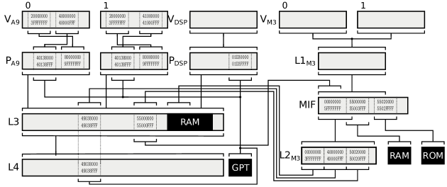
Different cores must thus issue different physical addresses (after MMU translation) for the same resource. For example, the GPTIMER5 timer device has (at least) three physical addresses depending on the accessing core: an A9 uses 0x40138000, a DSP uses 0x01D38000 and a DMA-capable device on the L3 interconnect uses 0x49038000.
Consider also the M3 cores, which use two address translation levels: a shared cache with L1 MMU means both cores use the same virtual address space at all times. The output of this MMU is fed into an address splitter and forwarded to local ROM or RAM, or translated by another, “L2” MMU providing a 1.5GB window starting at 0x0 in the L3 interconnect. The M3’s thus never see main system RAM at the same physical address as the A9 cores. Figure 1 shows a simplified view of addressing on the OMAP.
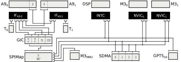
An interrupt raised by a device on the OMAP4460 can be routed to a single designated core or one dynamically selected. Cores themselves can also send interrupts between themselves. Figure 2 shows a subset of the interrupt topology on the chip. The A9 cores each have private timer interrupts. Devices like the SDMA engine can generate four different interrupts, of which two can be sent to any core, and two cannot be sent to the DSP. Interrupts appear with different numbers in the M3 and A9 cores. The A9 cores can initiate interrupts among themselves but not target other cores. Interrupts from devices like the on-chip GPTIMER5 cannot be routed to the M3s. M3 page faults interrupt an A9 core.
Similar complexity exists in almost all modern systems, including PCs (as we discuss below). Sophisticated CAD systems, market volumes, and Moore’s law have led to a great profusion in different platforms.
Reasoning about software running on this system clearly can neither rely on unique nor unambiguous physical addresses, even ignoring the effect of caches and “conventional” MMUs. Software is also constrained in terms of which interrupts can be received by which threads. It is not possible to make strong formal statements about the semantics of software running on the OMAP4460 or any other SoC without a formal description which captures the complexity of this addressing network. Moreover, correct software operation requires the various levels of address translation and access control to be programmed accordingly. Verifying system software on such a range of platforms is simply not feasible without a clear specification of how the hardware handles interrupts and memory references.
Our contributions in this paper are as follows. We make the case for a formal representation of hardware to help systems programmers understand the hardware at hand, and present a model and its syntax (section 2) to express and reason about interrupt routing, address spaces and their interactions. We express the hardware configuration of three different systems in subsections 3.1 to 3.3 and give reduction results and algorithms in section 4. We compare our work with the literature in section 5 followed by a presentation of a roadmap of future work in section 6 and conclude in section 7.
2 Model and Syntax
In this section, we give a brief description of our model and refer to Appendix A for a full description. We model the system’s handling of emitted addresses by a decoding net: a directed graph where each node represents a hardware component. Addresses and interrupts vectors are natural numbers. We use the term address and interrupt vector interchangeably in this paper. Decoding of an address starts at a particular node. Thus, a name is an address qualified by the node at which it is decoded. We therefore define a name as a tuple of i) a node identifier (nodeid) and ii) an address (addr). Nodes are labeled with natural numbers. A decoding net is then an assignment of nodes to identifiers.
Hardware components either accept addresses (e.g. RAM or device registers), they translate addresses and pass them on (e.g. MMU or lookup tables), or both (e.g. caches). A node is completely defined by two properties: a set of accepted addresses and a set of names it decodes an input address to. Formally:
The result of is the set of addresses accepted by a node without forwarding; The result of is the set of translated names for each input address. The same model can also be used to represent interrupt delivery where a node forwards interrupts (e.g. interrupt controllers) or accepts them (e.g. CPUs). All definitions are formalized in Isabelle/HOL, and all results we present are proven in the accompanying Isabelle theories. We want to emphasize that our model captures the static state of the system. Dynamic aspects such as concurrency and caching can be modeled on top of the decoding net, something we plan to tackle in the future.
The model allows a node to both accept and translate an address, and to translate an address to multiple outputs — real memory hardware doesn’t, but interrupt controllers can and it is useful while normalizing nodes. Every decoding net defines a decode relation and an accepted-names-set (names accepted anywhere in the net):
From these, we define the resolution function, which maps an input name (an address presented to a particular node) to a set of resolved names: the nodes at which the input address could end up being accepted, together with the translated input address to that node.
This is the input name if and only if the start node accepts the start address, and then all names reachable recursively via the decode relation. The termination of this recursion depends on the structure of the net, specifically the presence of loops. We present a necessary and sufficient condition for termination in section 4.
Nets are expressed in the following concrete syntax (EBNF, terminals are bold). This corresponds to the abstract syntax of section A.7.
Here all translations are specified by mapping a contiguous block of input addresses (specified by range ) to some output node, with all address values shifted to a new block base address. Nodes are specified by a finite set of accepting and mapping blocks and may be initialized using an overlay (over). If so, the node maps all input addresses 1–1 to the specified overlay node, unless they are captured by an accept or map block. Nodes are assigned identifiers with is or are (for repeated nodes). One can use the identifier instead of the assigned number when referring to the node. The map specification allows us to declare multiple destinations, which is necessary to describe interrupt systems.
In the following section, we demonstrate that this syntax, together with our model, concisely represents the address decoding of real hardware. In section 4 we further show that our model supports reasoning about address translation, for example by showing that networks can be reduced to a normal form, and that this reduction can be expressed by a simple algorithm on the concrete representation of the network i.e. that the representation refines the model.
3 Modeling Real Systems
We now express real systems (all of which we use for Barrelfish development) using the syntax from the previous section. We present the OMAP4460 SoC and two different x86 systems here. In addition, we show fully detailed models of those systems (B.1to B.3) and two additional systems (cluster system B.5.1 and the Intel SCC B.4) in the appendix. We focus our modelling on software-visible hardware features. We represent a block of addresses in the form with a (hex) prefix followed by zeros and the block size is e.g. 0x20000000-0x20000fff is represented as with a block size is 12-bits (4kB).
| L4is | |||||
| GPTis |
| MIFis | |||
| L3is |
3.1 A Mobile Device SoC: the OMAP4460
We introduced the OMAP4460 [19] in section 1. Each core (A9, M3 and DSP) has a distinct view of the system: some resources are core-private while others appear at different addresses, etc. We show examples of addressing and interrupt models (Figures 1 and 2) and refer to section B.1 for the full model.
Accessing DRAM from the A9 and M3 cores:
From the A9 core’s virtual address space, , the address 0x20000000 is translated and forwarded to (, 0x8000000) which overlays the L3 interconnect address space. L3 accepts the input and decoding terminates. Addresses from the are handled similarly. The M3 cores share the translation tables and hence accesses from are overlaid onto which maps and forwards addresses to the MIF, an address splitter. In our case, outputs address 0x0 which is forwarded by the MIF to the and further translated to 0x80000000 and forwarded to and accepted by L3.
Accessing the GPTIMER5 device:
The GPTIMER5 has multiple names that resolve to the GPT node: , , and , along with that means that and can also access GPT as they overlay L3.
Almost a loop:
We can construct a configuration where an access goes through the same address space twice, but we can show that resolution still works as the two decoding steps have different addresses. We start at the and the decoding steps go through , L3, L4 and end up in . This is the same node where we started suggesting a loop in the decoding, however the address is different. The MIF now maps the request to
SDMA triggers interrupt 2:
The SDMA device can generate four different interrupts. We model this as as a node that maps consecutive vectors starting from zero. Once it triggers interrupt 2 in the SDMA node, the interrupt will be forwarded to multiple controllers with different vectors. Specifically, it will be multicast towards and of the M3 subsystem. Since the NVICs are configured to ignore (mask) the interrupt, the nodes will neither accept nor map these interrupts. SPIMap translates the vector and forwards the signal to and is finally accepted
| SDMAis | |||
| GICis |
| SPIMapis | |||||
3.2 A Desktop PC
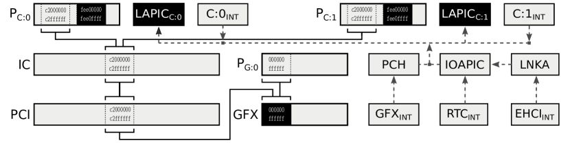
Our example desktop machine has a quad-core processor, 32GB of main memory and several I/O devices. We focus on two aspects of the memory model: a resource can respond to multiple addresses, and different resources respond to the same address. We further highlight the diversity of interrupt paths and vector formats. The relevant nodes (with 2 cores) are shown in Figure 3; the full model is in section B.2.
| IOAPICis | |||
| PCHis | |||
| IOAPICis |
| ICis | PCIis | ||||
| GFXis | |||||
| LNKAis | |||||
Address homonyms:
Consider cores in Figure 3. If they are using the same MMU page table one might think – erroneously – that they access the same view of physical memory. In fact, core-physical address 0xfee00000 (the local APIC address) on each core is accepted locally by both and . Each core’s MMU sees a different physical address space.
Address synonyms:
Conversely, a single resource, the GDDR region of GFX, appears at multiple addresses depending on the starting node. For instance will decode to . The same resource can be reached via a different address: . Physical addresses are not unique identifiers for the resource.
Message-signalled interrupts:
The GPU issues message signalled interrupts (MSI), memory writes to a platform-specific address range with a data word. We start with which is translated to a memory write to . We model this MSI as the concatenation of the address and data word since PCH is able to distinguish both. The PCH transforms these memory writes back to a regular interrupt message, here forwarded to which accepts the signal.
Legacy interrupt path:
The EHCI USB controller raises a legacy interrupt, which appears at . It propagates to the PCI link device LNKA with vector zero, which redirects it to the IOAPIC with vector 4. The IOAPIC is configured to forward interrupt number 4 to , with vector 48. Alternatively, the RTC device follows a similar path to the EHCI but it is directly connected to the IOAPIC. The decoding steps are .
Vector sharing:
The ARM platform (as in section 3.1) separates interrupts generated by peripheral devices and inter-processor interrupts initiated by software. The Intel x86 platform in contrast does not, and so for each core we split inbound () and outbound () interrupts into separate nodes (see section 4 for proof). In our example, triggers an interrupt which decodes to the same destination as the . We start with which is directly forwarded to the accepting node . Sharing may be unavoidable: an MSI device can issue up to 2048 different interrupts while an x86 core can only distinguish 256 vectors.
3.3 A Heterogeneous x86 Server
Servers, particularly for high-performance computing, are more complex than commodity desktops. Our example has 2 10-core sockets, each with its own DRAM controller, PCIe root complex, and IOMMU. Both PCIe buses have a Xeon Phi co-processor with 57 cores and 6GB GDDR RAM. The host cores support virtualization, including nested paging. This hardware is discussed in more detail in [11]).
The features we highlight (and make the server different from the desktop) are shown in Figure 4: the NUMA memory topology, PCI devices accessing each other’s memory through the IOMMU [14], and aliasing in the same address space. We refer to section B.3 for a full model.
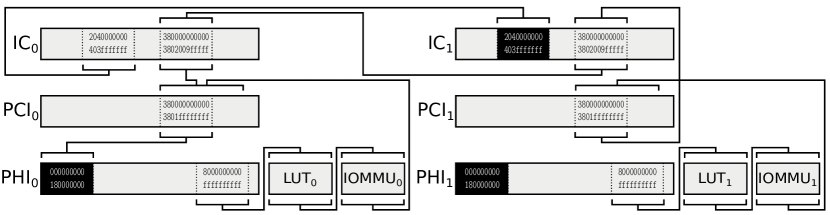
NUMA topology:
The NUMA nodes are abstracted by and . We model the behavior as follows: starting from decodes to a forward to with the same address and is accepted (remote access). Local accesses start from and are directly accepted by .
Aliasing:
The Xeon Phi can be configured such that its local GDDR region is aliased through the system memory interface. In our example, emitted addresses are directly accepted by whereas triggers the translation chain: . Here, input address decodes to , i.e. there are multiple addresses for this RAM cell: the LUT and IOMMU allow multiple mappings, although notably with different coherency and latency characteristics.
PCI-PCI access:
The local resources of can be accessed from through the system memory region: emitted address is forwarded and mapped through and to the interconnect . This address is in the range of the other socket, is forwarded there, and eventually accepted by .
Interrupts:
The main difference from the system in section 3.2 is the IOMMU’s interrupt controller on the path between devices and host cores. The Xeon Phis can raise regular PCIe interrupts, but also have their own local interrupt subsystem resembling another x86 system. These two subsystems are isolated: an interrupt on the Xeon Phi cannot be directly forwarded to the host or vice versa, another example of the limited reachability we referred to in section 3.1.
4 Reductions and Algorithms
The purpose of this model is to accurately represent the complex structure of address resolution and interrupt routing in a format that can be easily generated and manipulated at runtime. We now demonstrate that the model also has nice logical properties: it is amenable to formal analysis and the verification of routines that interpret or manipulate the concrete syntax. All results presented here are verified, and presented with a reference to the proof in the accompanying Isabelle/HOL source.
4.1 Termination
The underlying model, as introduced in section 2, is strictly graphical—it is defined entirely by the decode relation and the accept set. This permitted us to directly specify the hardware behavior, including decoding loops, but says nothing directly about an agent’s view of the system. Which resources are visible at such and such an address, in such and such an address space? The function provides the link, giving a mapping from local names (addresses relative to a viewpoint) to global names (nodes that may accept the address, and the local address at which they accept it).
HOL is a logic of total functions, and we can thus express the mapping from (address space, address) to (a set of) resources as a function if, and only if, the decoding process terminates. This occurs when every path in the decode relation beginning at the input address is finite. We express this as the existence of some well-formed ranking function , that decreases on every step of the decode relation (section A.3):
Termination follows as is bounded below by (here means that resolution terminates from i.e. the arguments are in the domain of the function (section A.4):
The duality between the graphical and operational views of an address space is fundamental: the result of any well-defined resolution is the set of names reachable via the decode relation (i.e. lie in the image of the reflexive, transitive closure of the relation), that refer to actual resources (i.e. are in the accept set, section A.2):
This result lets us freely substitute one view of the system for another.
4.2 Normalization and Refinement
To use this model, we need efficient algorithms in the OS to manipulate it e.g. calculate the set of visible resources from a processor. This information is implicit in the graphical model, but not easily accessible. We might, for example, wish to produce a flattened representation that preserves the view from each processor, while making such a query efficient. One way to achieve this is to split all nodes into nodes that only accept addresses (resources), and ones that only map to other nodes (address spaces). Then merging, or flattening the mapping nodes gives us the desired result.
We would like to verify such algorithms. We show here that we can define and verify equivalence-preserving transformations on the semantic model, together with a notion of refinement. In the remainder of this section, we demonstrate equivalence-preservation and refinement for the first step: splitting, with reference to the accompanying sources. Further results regarding flattening are also provided in the Isabelle sources for the interested reader.
Two nets are view-equivalent, written if all observers in have the same view (i.e. the results of are the same), modulo some renaming ( and ) of the accepting nodes. Let be greater than the label of any extant node. The split net is then defined as (section A.6.1):
This new net is view-equivalent to the original, with names that were accepted at now accepted at , and no node both accepting and translating addresses (section A.6.1):
| (1) |
Splitting on the concrete representation is a simple syntactic operation. Each node is replaced as follows (section A.8):
Refinement is, as usual, expressed as the commutativity of the operations (here and ) with the state relation (here , which constructs a net from its syntactic representation, section A.8):
| (2) |
Combining Equation 1 with Equation 2 we have the desired result, that the concrete implementation preserves the equivalence of the nets constructed by parsing (section A.8):
| (3) |
Together with the equivalent result for flattening, we can verify that the physical address spaces that we read directly from the transformed model are exactly those that we would have found by (expensively) traversing the original hardware-derived model for all addresses.
5 Related Work
The difficulty of writing OS code in C for increasingly complex hardware has led to several non-formal mechanisms for the OS to discover, and configure, the hardware platform at runtime.
System firmware provides software with configuration information through ACPI [8] tables and, more recently, UEFI [9]. Both provide somewhat abstracted information about the NUMA affinity of memory controllers and other devices, information required to write fast memory intensive applications. Hardware connection standards like PCI Express provide a measure of device enumeration (including address discovery and interrupt routing requirements), giving a hierarchy of the PCI bridges and connected devices. Schupbach et al. [18] applied a declarative approach to the configuration of the memory windows of PCI bridges. Similarly, USB devices are discovered by hierarchical enumeration of hubs. Processors provide cache hierarchy data, for example using the x86 cpuid instruction.
A more comprehensive description of a hardware platform is attempted by Device Trees [6], which describes a binary file format designed for bootloaders to find hardware at startup and is now used extensively in the Linux kernel to handle non-discoverable devices. While a Device Tree captures some information about, for example, the addresses of devices as seen from a single core (the root of the tree), it has no well-defined semantics for interpreting the data. Moreover, it is not well-suited for heterogenous systems where a single hierarchy is a poor match for hardware, and does not capture caches, TLBs, or the view of the system from DMA-capable devices.
We are not aware of any work on formalizing the interrupt subsystem. Commodity operating systems often only support a specific mode of interrupt delivery. Linux for instance always distributes all interrupts to all CPUs [5]. Similarly, FreeBSD refers to interrupts using the ACPI enumeration resulting in clashes when naming MSI sources. The system assumes that MSIs directly reach the CPUs, which is no longer true since the introduction of the I/OMMU [4].
Alglave et al. [3] applied the technique of litmus testing to define allowable execution traces in the presence of memory operation reordering (e.g. write buffering or speculation), and test them against real hardware. Further work of the authors [2, 7] develops this into a semantic model of weak-memory systems (such as IBM Power and ARM), in particular taking advantage of a close relationship with ARM to ensure the faithfulness of their models to (the intended behavior of) production silicon. Our work is complementary: we provide a means to specify and reason about the connectivity of address spaces in a system, on top of which a rigorous model of weak memory would fully define the behavior of the memory system.
Earlier work in hardware verification, such as that of Velev [20] or Ganai [10], considered the influence of memory system microarchitecture on the verification of instruction-set semantics. The widespread adoption of out-of-order execution and weak memory models has greatly increased the complexity of the problem, which as mentioned is now being tackled. Our focus is rather on the explosion of complexity in the physical interconnection of devices, an area that is not yet well studied.
On the programming-language side, there has long been interest [21, 17] in the interaction of language-specified memory models (particularly that of Java, and now C11/C++11) and that provided by the hardware. Again, these models do not describe the low-level interconnection of hardware, which has been relegated to an ‘OS problem’, where it is solved (badly) with tools such as device trees and ACPI.
6 Roadmap
While our model is a useful first step, we are extending it considerably as we apply it to engineering Barrelfish. We list our future directions here.
We used the same model of interrupts and memory because both resemble network forwarding, but in reality they are deeply connected in hardware: message-signaled interrupts and inter-processor interrupts are initiated by writing to memory addresses, and virtualization hardware can translate interrupts into memory writes. Unifying memory and interrupts is a natural next step.
We also do not distinguish reads, writes, and other types of transaction in our addressing model. In practice, different request types may traverse different paths in the interconnect and/or be accepted by different components: examples include read-only memory protection, and some PCIe DMA controllers which can only copy data in one direction for certain address ranges.
A further step is extending our static model to capture dynamic state, starting with caches. Caches are a challenge because they may or may not respond to an address depending on their contents, they may themselves emit addresses to other caches and resources, they may also perform address translation, and they can be bypassed by non-cacheable reads and writes. Our current model expresses the set of resources that may respond to a request, but not which resource actually responds. Furthermore, the future behavior of the cache changes in response to requests. Coherence protocols like MOESI also allow a line to be fetched from another cache instead of main memory. Not all cores or devices might participate in the coherence protocol, but others might be able to directly write to remote caches. In both cases, caches can be inconsistent with main memory – something our model cannot yet handle.
The dynamic state of a system also includes the configuration of translation units. Unfortunately, such units (lookup tables, interrupt controllers, etc.) have varying constraints on their configuration. Some interrupt controllers perform fixed translation, some allow selective masking, some can remap blocks of interrupt requests, and others can arbitrarily translate vectors. Memory translation can be achieved with page tables or lookup tables of varying, fixed-size pages. The addresses that can be mapped between address spaces can be limited in range or domain.
Our goal is, given a topology, these constraints, and a desired end-to-end view, to synthesize a correct configuration for the translation units in the system. Since many feasible configurations can exist, we would also define an optimization goal such as minimizing the required space for page tables or interrupt mapping tables in limited-resource hardware like IOMMUs.
Synthesizing a valid configuration is insufficient for correct operation, however. The system requirements are dynamic: devices are hotplugged, and brought up and down by power management functions. Threads are migrated between cores by schedulers, etc. This means that the transition between correct configurations, achieved by reprogramming individual controllers or management units, must be achieved without violating security or correctness guarantees, by creating a sequence of correct intermediate states and/or determining which tasks must be paused while reconfiguration occurs. A simple example is reconfiguring a set of memory translation units in sequence such that at no point does a process have unauthorized access to an area of main memory, and that caches are consistent at all points.
Finally, while we capture the semantics of memory access and interrupts, the performance of such operations also depends on the platform configuration. By annotating mapping functions with performance characteristics, our model might be used to generate hardware optimized data structures and messaging protocols as in [15], or minimized interrupt latency by choosing an appropriate delivery mechanism [12].
7 Conclusion
Contemporary hardware exposes a memory system and interrupt system structure more complicated than usually assumed. We have seen three examples of current systems that violate common assumptions such as that a physical address uniquely identifies a resource or that interrupts can be directed to all CPUs. This implies that there is no — or had never been a — single physical address space and interrupts can not be directed to all cores anymore.
We presented a formal model to express the interactions and topologies of address spaces and interrupts. Our model is capable of capturing the characteristics of a broad range of current systems and we show view equivalence preserving transformations that can be used to convert a complex system model into a flattened representation.
References
- [1]
- [2] Jade Alglave (2012): A Formal Hierarchy of Weak Memory Models. Form. Methods Syst. Des. 41(2), pp. 178–210, 10.1007/s10703-012-0161-5.
- [3] Jade Alglave, Luc Maranget, Susmit Sarkar & Peter Sewell (2010): Fences in Weak Memory Models. In: CAV’10, Edinburgh, UK, pp. 258–272, 10.1007/978-3-642-14295-625.
- [4] John Baldwin (2008): PCI Interrupts for x86 Machines under FreeBSD. In: Proceedings of the BSDCan Conference, pp. 1–22.
- [5] Daniel P. Bovet & Marco Cesati (2005): Understanding the Linux Kernel - from I/O ports to process management: covers version 2.6 (3. ed.), chapter 4.6. O’Reilly. Available at http://www.oreilly.de/catalog/understandlk/index.html.
- [6] devicetree.org (2016): Devicetree Specification. http://www.devicetree.org/specifications-pdf.
- [7] Shaked Flur, Kathryn E. Gray, Christopher Pulte, Susmit Sarkar, Ali Sezgin, Luc Maranget, Will Deacon & Peter Sewell (2016): Modelling the ARMv8 Architecture, Operationally: Concurrency and ISA. In: POPL ’16, St. Petersburg, FL, USA, pp. 608–621, 10.1145/2837614.2837615.
- [8] UEFI Forum (2011): ACPI 5.0 Specification. http://www.acpi.info/downloads/acpispec50.pdf.
- [9] UEFI Forum (2016): UEFI Specification 2.6. http://www.uefi.org/specifications.
- [10] Malay K. Ganai, Aarti Gupta & Pranav Ashar (2005): Verification of Embedded Memory Systems Using Efficient Memory Modeling. In: DATE ’05, pp. 1096–1101, 10.1109/DATE.2005.325.
- [11] Simon Gerber, Gerd Zellweger, Reto Achermann, Kornilios Kourtis, Timothy Roscoe & Dejan Milojicic (2015): Not Your Parents’ Physical Address Space. In: HOTOS’15, Switzerland, pp. 16–16. Available at http://dl.acm.org/citation.cfm?id=2831090.2831106.
- [12] Intel Corporation (2009): Reducing Interrupt Latency Through the Use of Message Signaled Interrupts . Online. Accessed 2017-01-13. White Paper 321070. http://www.intel.co.za/content/dam/www/public/us/en/documents/white-papers/msg-signaled-interrupts-paper.pdf.
- [13] Intel Corporation (2009): Single-chip Cloud Computer. Online. Accessed 2017-01-09. http://www.intel.com/content/dam/www/public/us/en/documents/technology-briefs/intel-labs-single-chip-cloud-overview-paper.pdf.
- [14] Intel Corporation (2016): Intel Virtualization Technology for Directed I/O, revision 2.4 edition.
- [15] Stefan Kaestle, Reto Achermann, Roni Haecki, Moritz Hoffmann, Sabela Ramos & Timothy Roscoe (2016): Machine-aware Atomic Broadcast Trees for Multicores. In: OSDI’16, Savannah, GA, USA, pp. 33–48. Available at http://dl.acm.org/citation.cfm?id=3026877.3026881.
- [16] Simon Peter, Adrian Schüpbach, Dominik Menzi & Timothy Roscoe (2011): Early experience with the Barrelfish OS and the Single-Chip Cloud Computer. In: MARC’11, KIT Scientific Reports, pp. 17–17. Available at http://dl.acm.org/citation.cfm?id=2831090.2831107.
- [17] Susmit Sarkar, Kayvan Memarian, Scott Owens, Mark Batty, Peter Sewell, Luc Maranget, Jade Alglave & Derek Williams (2012): Synchronising C/C++ and POWER. In: PLDI’12, ACM, New York, NY, USA, pp. 311–322, 10.1145/2254064.2254102.
- [18] Adrian Schüpbach, Andrew Baumann, Timothy Roscoe & Simon Peter (2011): A Declarative Language Approach to Device Configuration. In: ASPLOS XVI, Newport Beach, California, USA, pp. 119–132, 10.1145/1950365.1950382.
- [19] Texas Instruments (2014): OMAP44xx Multimedia Device Technical Reference Manual. Version AB, www.ti.com/lit/ug/swpu235ab/swpu235ab.pdf.
- [20] Miroslav N. Velev (2001): Automatic Abstraction of Memories in the Formal Verification of Superscalar Microprocessors. In: TACAS 2001, pp. 252–267, 10.1007/3-540-45319-918.
- [21] Foivos S. Zakkak & Polyvios Pratikakis (2016): DiSquawk: 512 Cores, 512 Memories, 1 JVM. In: PPPJ ’16, Lugano, Switzerland, pp. 2:1–2:12, 10.1145/2972206.2972212.
Appendix A Decoding Net Model
This appendix presents the formal development (in Isabelle/HOL) of the decoding net model outlined in section 2, together with proofs of some key results. The text here is generated directly from the Isabelle sources, with some sections excluded for space and not being (in our subjective opinion) particularly interesting. The proofs may therefore occasionally refer to definitions and lemmas which are not stated here—in any such case, the full, machine-checked proof is available in the theory files associated with this paper.
First, we nail down some types. For ease in getting started, we’re using natural numbers for addresses. It should be possible to use the same definitions to handle finite-length words without much modification.
type-synonym nodeid nat
type-synonym addr nat
A name is a qualified address: which is defined with respect to some context, in this case the node at which decoding begins.
type-synonym name nodeid addr
A node can accept an input address, in which case resolution terminates here, or it can translate it into an input address for another node, or both. We allow the sets of accepted and translated addresses to overlap to model nondeterministic behaviour e.g. a cache, which has a well-defined translation for every input address, but could potentially respond to any request with a locally-cached value. In general, we’re interested in the set of (node, address) pairs at which a given input address might be accepted.
record node
accept addr set
translate addr name set
\isadelimproof\endisadelimproof\isatagproof\endisatagproof\isadelimproof\endisadelimproof
A.1 Address Decoding Nets.
A decode net is an assignment of nodes to identifiers.
type-synonym net nodeid node
One step of address decoding, mapping an input name (node, address) to an output name (or nothing).
definition decode-step net name name set
where
decode-step net name translate net fst name snd name
The decode relation is, in general, a directed graph. If it’s actually a DAG, then all addresses can be decoded in a well-defined manner.
definition decodes-to net name rel
where
decodes-to net n n n decode-step net n
The set of names that can be accepted anywhere in this decoding net i.e. the union of the accept sets of all nodes.
definition accepted-names net name set
where accepted-names net nda nd a a accept net nd
\isadelimtheory\endisadelimtheory\isatagtheory\endisatagtheory\isadelimtheory\endisadelimtheory
A.2 Resolution
To resolve an input name, start with the name itself if the net accepts it, and recurse on all names reachable via the decodes-to relation
function domintros resolve net name name set
where resolve net n
n accepted-names net
n if nn decodes-to net then resolve net n else
\isadelimproof \endisadelimproof\isatagproofbypat-completeness auto
\endisatagproof\isadelimproof\endisadelimproof\isadelimproof\endisadelimproof\isatagproof\endisatagproof\isadelimproof\endisadelimproof\isadelimproof\endisadelimproof\isatagproof\endisatagproof\isadelimproof\endisadelimproof\isadelimproof\endisadelimproof\isatagproof\endisatagproof\isadelimproof\endisadelimproof
The defining relation for resolve is simply decodes-to:
lemma resolve-rel-decodes-to
resolve-rel x y fst x fst y snd x snd y decodes-to fst x
\isadelimproof \endisadelimproof\isatagproofbycases x cases y auto elimresolve-relcases introresolve-relintros
\endisatagproof\isadelimproof\endisadelimproof\isadelimproof\endisadelimproof\isatagproof\endisatagproof\isadelimproof\endisadelimproof\isadelimproof\endisadelimproof\isatagproof\endisatagproof\isadelimproof\endisadelimproof\isadelimproof\endisadelimproof\isatagproof\endisatagproof\isadelimproof\endisadelimproof\isadelimproof\endisadelimproof\isatagproof\endisatagproof\isadelimproof\endisadelimproof\isadelimproof\endisadelimproof\isatagproof\endisatagproof\isadelimproof\endisadelimproof\isadelimproof\endisadelimproof\isatagproof\endisatagproof\isadelimproof\endisadelimproof
We can express resolution in an equivalent non-recursive fashion, as the image of the closure of the decoding relation:
lemma resolve-eval
assumes dom resolve-dom net n
shows resolve net n accepted-names net decodes-to net-1∗ “ n
\isadelimproof\endisadelimproof\isatagproof\endisatagproof\isadelimproof\endisadelimproof
A.3 Well-Formed Decoding Nets
The most general condition for the decoding of a given name to be well-defined is that the decoding process terminates i.e. that all paths of decoding steps (elements of the decodes-to relation) are finite (we eventually reach a node that either accepts its input address, or faults).
A well-formed rank function f assigns a natural number to every name, such that if some name n decodes to n, f n f n. From this, it is trivial to show that decoding terminates. Note that it is only necessary for the ranking to be well-formed for the name that we’re resolving: it may not be possible to assign a consistent ranking to all names, that is well-formed for all starting points, although in well-designed systems it probably should be.
definition wf-rank name nat name net bool
where
wf-rank f n net
x y xn rtrancl decodes-to net yx decodes-to net f y f x
\isadelimproof\endisadelimproof\isatagproof\endisatagproof\isadelimproof\endisadelimproof\isadelimproof\endisadelimproof\isatagproof\endisatagproof\isadelimproof\endisadelimproof\isadelimproof\endisadelimproof\isatagproof\endisatagproof\isadelimproof\endisadelimproof\isadelimproof\endisadelimproof\isatagproof\endisatagproof\isadelimproof\endisadelimproof\isadelimproof\endisadelimproof\isatagproof\endisatagproof\isadelimproof\endisadelimproof
We use our well-formedness predicate to insist that all node both accept and translate a finite set of addresses. While this isn’t strictly necessary for a lot of the theory, it’s essential for termination.
definition wf-net net bool
where wf-net net
nd finite accept net nd
n resolve-dom netn finite decodes-to net-1 “ n
\isadelimproof\endisadelimproof\isatagproof\endisatagproof\isadelimproof\endisadelimproof\isadelimproof\endisadelimproof\isatagproof\endisatagproof\isadelimproof\endisadelimproof\isadelimproof\endisadelimproof\isatagproof\endisatagproof\isadelimproof\endisadelimproof
A.4 Termination
If we can supply a ranking function that is well-formed for all names reachable from the name we wish to decode, then the decoding function is well-defined here (this name lies in its domain).
lemma wf-resolve-dom
fixes f name nat and n name and net net
assumes wf-at wf-rank f n net
shows resolve-dom netn
\isadelimproof\endisadelimproof\isatagproofproof
{
We argue by (strong) induction on the rank of the name, but we need to carry the assumption of reachability into the induction hypothesis (as otherwise we can’t appeal to a well-formed ranking. We then trivially discard this assumption as n is reachable from itself, by definition.
fix a
assume an decodes-to net∗
hence resolve-dom neta
proofinduct f a arbitrarya rulenat-less-induct
fix b
Assume the current node is reachable, and all reachable nodes of lesser rank lie in the domain of resolve.
assume reachable bn decodes-to net∗
and IH mf b x m f x xn decodes-to net∗ resolve-dom net x
We show that the arguments of any recursive call to resolve must lie in the domain, as new node is both reachable, and has strictly lesser rank, thanks to well- formedness.
show resolve-dom net b
proofrule resolve-domI
fix a
Assume that there is a translation/decoding step. We don’t need to show anything for the terminating case, as there’s no recursive call.
assume step ab decodes-to net
The two names lie in the decoding relation, and the new name is also reachable from n.
from step reachable have reachable-yz an decodes-to net∗ bysimp
From the (assumed) reachability of b, we can appeal to well-formedness to show that the rank decreases.
from wf-at reachable step have f a f b
unfolding wf-rank-def byblast
Thus with the reachability of the new name, we have the result by appealing to the induction hypothesis.
with reachable-yz IH show resolve-dom net a byblast
qed
qed
}
Finally, we discharge the reachability assumption.
thus ?thesis byauto
qed\endisatagproof\isadelimproof\endisadelimproof
This is the converse of the previous lemma, for decoding nets that with finite branching: If a single decoding step maps a name to a finite number of new names, then there must exist a well-formed ranking for each resolvable name.
lemma mkrank
fixes n name and net net
assumes branching n resolve-dom netn finite decodes-to net-1 “ n
shows resolve-dom netn f wf-rank f n net
\isadelimproof\endisadelimproof\isatagproofproofinduction netn arbitraryn ruleaccpinduct
fix n
Assume that there exists a well-formed ranking for every direct descendent.
assume IH n resolve-rel net n net n f wf-rank f n net
and dom y resolve-rel y net n resolve-dom y
have rd resolve-dom netn byblast introaccpintros dom
By appealing to the axiom of choice (although as we’re finite we could do without), construct g which, for every ancestor n of n, gives a ranking function that is well-formed at n.
from IH
have n decodes-to net-1 “ n f wf-rank f n net
byblast introresolve-relintros
hence g n decodes-to net-1 “ n wf-rank g n n net
byrule bchoice
then obtain g where wf-g n decodes-to net-1 “ n wf-rank g n n net
byblast destbchoice
For any node n, this is the set of its ancestors that are direct descendents of n i.e. the set of nodes that any path from n to n must pass through. This set is finite.
let ?ancs n n nn decodes-to net nn decodes-to net∗
have x ?ancs x decodes-to net-1 “ n byauto
with branching rd have finite-ancs x finite ?ancs x byblast destfinite-subset
From g, construct g, by taking, for each n, the least rank assigned it by any of the well-formed rankings associated with its ancestors. This new ranking is still well-formed for all of the direct descendents of n.
let ?g n Min n g n n ‘ ?ancs n
have wf-g n decodes-to net-1 “ n wf-rank ?g n net
proofintro ballI wf-rankI
fix w x y
Assume y and x are reachable, and in the decode relation. They therefore have the same set of ancestors.
assume w decodes-to net-1 “ n
hence wn wn decodes-to net bysimp
assume xw xw decodes-to net∗
and yx yx decodes-to net
We show that for any ancestor of x, the rank assigned x is greater than the new rank we’ve constructed for y, and thus so is the minimum over these i.e. g.
show ?g y ?g x
proofintro iffD2OF Min-gr-iff
The ancestors are finite, and there is at least one.
from finite-ancs show finite n g n x ‘ ?ancs x byauto
from wn xw show n g n x ‘ ?ancs x byblast
show an g n x ‘ ?ancs x Min n g n y ‘ ?ancs y a
proof
fix a
assume a n g n x ‘ ?ancs x
then obtain n where step n decodes-to net-1 “ n
and anc xn decodes-to net∗
and aeq a g n x byblast
As any ancestor n of x is also an ancestor of y, we can appeal to well-formedness to show that g n y g n x. It thus follows that the minimum is also lower.
from anc yx have yn decodes-to net∗ byauto
with step have g n y n g n y ‘ ?ancs y byblast
moreover from finite-ancs have finite n g n y ‘ ?ancs y byauto
ultimately have Min n g n y ‘ ?ancs y g n y byauto
also {
from step wf-g have wf-rank g n n net byblast
with yx anc have g n y g n x unfolding wf-rank-def byblast
}
finally show Min n g n y ‘ ?ancs y a bysimp addaeq
qed
qed
qed
We will appeal to the fact that we must be in the accessible portion of the decode relation to show that n can never appear as a descendent of itself, and can thus be assigned a higher rank than all of its descendents.
from rd have nacc n Wellfoundedacc decodes-to net
byauto destresolve-dom-decodes-to
Finally, we construct our ranking function by assigning to n a rank greater than any of its descendents. Doing so relies on there being only finitely many of these.
let ?max Max ?g ‘ decodes-to net-1 “ n
let ?h ?gn Suc ?max
have wf-rank ?h n net
We can show this be appealing to the well-formedness for each descendents that we just proved, and the fact that we assigned a greater rank to n.
proofrule wf-rank-step
fix y
assume yn yn decodes-to net
We must show that the ranking is still well-defined for all descendents, even though we’ve changed the rank assigned to n. This is where we need to know that n never appears as its own descendent.
show wf-rank ?h y net
proofrule wf-rankI
fix x z
assume xy xy decodes-to net∗
and zx zx decodes-to net
Appeal to the absence of loops in the accessible portion.
from xy yn have xreach xn decodes-to net+ byauto
with nacc have x-ne-n x n byauto destno-loops-acc
from zx xy yn have zn decodes-to net+ byauto
with nacc have z-ne-n z n byauto destno-loops-acc
from yn have ydecodes-to net-1 “ n bysimp
with wf-g have wf-g-y wf-rank ?g y net bysimp
Appeal to well-formedness.
from wf-g-y zx xy have ?g z ?g x unfolding wf-rank-def byblast
thus ?h z ?h x bysimp addx-ne-n z-ne-n
qed
Showing that the rank increases is now trivial.
from nacc yn have y-ne-n y n byauto destno-loops-acc
from branching rd yn
show ?h y ?h n
bysimp addy-ne-n intro le-imp-less-SucOF Max-ge auto
qed
thus f wf-rank f n net byblast
qed\endisatagproof\isadelimproof\endisadelimproof\isadelimproof\endisadelimproof\isatagproof\endisatagproof\isadelimproof\endisadelimproof\isadelimtheory\endisadelimtheory\isatagtheory\endisatagtheory\isadelimtheory\endisadelimtheory
A.5 View Equivalence
A view is a function that encodes the result of all address resolutions beginning at a given node.
type-synonym view addr name set
definition view-from nodeid net view
where view-from node net addr resolve net node addr
A remapping is a renaming of nodes, leaving addresses intact.
type-synonym remap nodeid nodeid
definition rename remap name name
where rename m n m fst n snd n
\isadelimproof\endisadelimproof\isatagproof\endisatagproof\isadelimproof
\endisadelimproofprimrec rename-list nodeid nodeid nodeid list nodeid nodeid
where rename-list f id
rename-list f ndnds x if x nd then f nd else x o rename-list f nds
Two nets are view-equivalent for some node, if the two views have the same domain, and give the same result for all addresses, modulo a renaming of accepting nodes.
definition view-eq nodeid remap net remap net bool
where view-eq nd x y
a resolve-dom snd xnda resolve-dom snd ynda
a resolve-dom snd xnda
rename fst x ‘ view-from nd snd x a
rename fst y ‘ view-from nd snd y a
definition view-eq-on nodeid set remap net remap net bool
where view-eq-on S x y ndS view-eq nd x y
Two nodes are equivalent (for a given net) if they have the same view.
definition node-eq net nodeid nodeid bool
where node-eq net nd nd
a resolve-dom netnda resolve-dom netnda
a resolve-dom netnda view-from nd net a view-from nd net a
\isadelimproof\endisadelimproof\isatagproof\endisatagproof\isadelimproof\endisadelimproof\isadelimproof\endisadelimproof\isatagproof\endisatagproof\isadelimproof\endisadelimproof\isadelimproof\endisadelimproof\isatagproof\endisatagproof\isadelimproof\endisadelimproof\isadelimproof\endisadelimproof\isatagproof\endisatagproof\isadelimproof\endisadelimproof\isadelimproof\endisadelimproof\isatagproof\endisatagproof\isadelimproof\endisadelimproof\isadelimproof\endisadelimproof\isatagproof\endisatagproof\isadelimproof\endisadelimproof\isadelimproof\endisadelimproof\isatagproof\endisatagproof\isadelimproof\endisadelimproof\isadelimproof\endisadelimproof\isatagproof\endisatagproof\isadelimproof\endisadelimproof\isadelimproof\endisadelimproof\isatagproof\endisatagproof\isadelimproof\endisadelimproof
Both view-equivalence and node-equivalence are proper equivalence relations.
lemma equivp-view-eq
nd equivp view-eq nd
\isadelimproof\endisadelimproof\isatagproof\endisatagproof\isadelimproof
\endisadelimprooflemma equivp-view-eq-on
fixes S nodeid set
shows equivp view-eq-on S
\isadelimproof\endisadelimproof\isatagproof\endisatagproof\isadelimproof\endisadelimproof\isadelimproof\endisadelimproof\isatagproof\endisatagproof\isadelimproof\endisadelimproof\isadelimproof\endisadelimproof\isatagproof\endisatagproof\isadelimproof\endisadelimproof\isadelimproof\endisadelimproof\isatagproof\endisatagproof\isadelimproof\endisadelimproof\isadelimproof\endisadelimproof\isatagproof\endisatagproof\isadelimproof\endisadelimproof\isadelimproof\endisadelimproof\isatagproof\endisatagproof\isadelimproof\endisadelimproof\isadelimproof\endisadelimproof\isatagproof\endisatagproof\isadelimproof\endisadelimproof\isadelimproof\endisadelimproof\isatagproof\endisatagproof\isadelimproof\endisadelimproof
Both equivalence relations preserve resolution.
lemma node-eq-resolve
fixes nd nd nodeid and net net and a addr
shows node-eq net nd nd resolve-dom netnda resolve net nda resolve net nda
\isadelimproof\endisadelimproof\isatagproof\endisatagproof\isadelimproof
\endisadelimprooflemma view-eq-resolve
fixes nd nodeid and x y remap net and a addr
shows view-eq nd x y resolve-dom snd xnda
rename fst x ‘ resolve snd x nda rename fst y ‘ resolve snd y nda
\isadelimproof\endisadelimproof\isatagproof\endisatagproof\isadelimproof\endisadelimproof\isadelimproof\endisadelimproof\isatagproof\endisatagproof\isadelimproof\endisadelimproof
View-equivalence is preserved by any further node renaming.
lemma view-eq-comp
view-eq nd fnet gnet view-eq nd h o fnet h o gnet
\isadelimproof\endisadelimproof\isatagproof\endisatagproof\isadelimproof\endisadelimproof\isadelimproof\endisadelimproof\isatagproof\endisatagproof\isadelimproof\endisadelimproof\isadelimproof\endisadelimproof\isatagproof\endisatagproof\isadelimproof\endisadelimproof
For transformations that add nodes, we need to know that the new node has no descendents or ancestors.
definition fresh-node net nodeid bool
where fresh-node net nd
a translate net nd a
x y xy decodes-to net fst x nd
accept net nd
\isadelimproof\endisadelimproof\isatagproof\endisatagproof\isadelimproof\endisadelimproof\isadelimproof\endisadelimproof\isatagproof\endisatagproof\isadelimproof\endisadelimproof\isadelimproof\endisadelimproof\isatagproof\endisatagproof\isadelimproof\endisadelimproof\isadelimtheory\endisadelimtheory\isatagtheory\endisatagtheory\isadelimtheory\endisadelimtheory
A.6 Equivalence-Preserving Transformations
A.6.1 Splitting Nodes
The acceptor accepts all addresses accepted by the original node, but translates none.
definition acceptor-node node node
where acceptor-node node node translate -
Forward all addresses to the acceptor node, maintaining existing translations.
definition redirector-node nodeid node node
where redirector-node nd node accept
translate a if a accept node then insert nda translate node a else translate node a
Split a node into an acceptor, that accepts all addresses accepted by the original node, and a redirector, which forwards all addresses that it would have accepted to the acceptor.
definition split-node nodeid nodeid net net
where split-node nd nd net
netnd redirector-node nd net nd nd acceptor-node net nd
We can represent the effect of node splitting by its action on the set of accepted names, and on the decoding relation. Recall from section A.2 that this is sufficient to fully define the result of resolution.
Splitting only adds the new decode edges:
lemma split-decode
nd nd a translate net nd a
decodes-to split-node nd nd net
decodes-to net a Pair nd a Pair nd a ‘ accept net nd\isadelimproof\endisadelimproof\isatagproof\endisatagproof\isadelimproof\endisadelimproof
Splitting only touches the named nodes:
lemma fresh-split-node
assumes fresh fresh-node net x
and neq x nd x nd
shows fresh-node split-node nd nd net x\isadelimproof\endisadelimproof\isatagproof\endisatagproof\isadelimproof\endisadelimproof
Splitting neither adds nor removes accepted names, it simply renames those accepted by the original node:
lemma split-accepted
assumes empty accept net nd
shows accepted-names split-node nd nd net rename idnd nd ‘ accepted-names net\isadelimproof\endisadelimproof\isatagproof\endisatagproof\isadelimproof\endisadelimproof
Splitting a node has no effect on the termination of resolve:
lemma split-node-domeq
fixes S nodeid set and nd nd nodeid and net net and nname
assumes neq nd nd
and wf-net wf-net net
and fresh fresh-node net nd
shows resolve-dom netn resolve-dom split-node nd nd netn\isadelimproof\endisadelimproof\isatagproof\endisatagproof\isadelimproof\endisadelimproof
The effect of splitting a node is just to rename anything that was accepted by the split node.
lemma split-node-resolveeq
fixes S nodeid set and nd nd nodeid and net net and nname
assumes neq nd nd
and wf-net wf-net net
and fresh fresh-node net nd
and dom resolve-dom netn
shows fst n nd
rename idnd nd ‘ resolve net n
rename id ‘ resolve split-node nd nd net n\isadelimproof\endisadelimproof\isatagproof\endisatagproof\isadelimproof\endisadelimproof
From these two lemmas, we have view-equivalence under splitting.
lemma split-node-eq
fixes S nodeid set and nd nd nodeid and net net
assumes neq nd nd
and wf-net wf-net net
and fresh fresh-node net nd
and notin nd S
shows view-eq-on S idnd nd net id split-node nd nd net\isadelimproof\endisadelimproof\isatagproof\endisatagproof\isadelimproof\endisadelimproof\isadelimproof\endisadelimproof\isatagproof\endisatagproof\isadelimproof\endisadelimproof
Since a single split preserves equivalence, so does splitting a finite list of nodes (Equation 1):
primrec split-all nodeid list nodeid nodeid net net
where split-all - net net
split-all ndnds f net split-node nd f nd split-all nds f net
\isadelimproof\endisadelimproof\isatagproof\endisatagproof\isadelimproof\endisadelimproof\isadelimproof\endisadelimproof\isatagproof\endisatagproof\isadelimproof\endisadelimproof\isadelimproof\endisadelimproof\isatagproof\endisatagproof\isadelimproof
\endisadelimprooflemma view-eq-split-all
assumes distinct distinct nds
and nonds nd f nd set nds
and fresh nd fresh-node net f nd
and inj inj-on f set nds
and wf wf-net net
and noS nd f nd S
shows view-eq-on S rename-list f nds net id split-all nds f net\isadelimproof\endisadelimproof\isatagproof\endisatagproof\isadelimproof\endisadelimproof\isadelimproof\endisadelimproof\isatagproof\endisatagproof\isadelimproof\endisadelimproof\isadelimproof\endisadelimproof\isatagproof\endisatagproof\isadelimproof\endisadelimproof\isadelimproof\endisadelimproof\isatagproof\endisatagproof\isadelimproof\endisadelimproof\isadelimproof\endisadelimproof\isatagproof\endisatagproof\isadelimproof\endisadelimproof\isadelimproof\endisadelimproof\isatagproof\endisatagproof\isadelimproof\endisadelimproof\isadelimproof\endisadelimproof\isatagproof\endisatagproof\isadelimproof\endisadelimproof\isadelimproof\endisadelimproof\isatagproof\endisatagproof\isadelimproof\endisadelimproof\isadelimproof\endisadelimproof\isatagproof\endisatagproof\isadelimproof\endisadelimproof\isadelimproof\endisadelimproof\isatagproof\endisatagproof\isadelimproof\endisadelimproof\isadelimproof\endisadelimproof\isatagproof\endisatagproof\isadelimproof\endisadelimproof\isadelimproof\endisadelimproof\isatagproof\endisatagproof\isadelimproof\endisadelimproof\isadelimproof\endisadelimproof\isatagproof\endisatagproof\isadelimproof\endisadelimproof\isadelimproof\endisadelimproof\isatagproof\endisatagproof\isadelimproof\endisadelimproof\isadelimtheory\endisadelimtheory\isatagtheory\endisatagtheory\isadelimtheory\endisadelimtheory
A.7 Abstract Syntax for Nets
This is the abstract syntax, corresponding to the concrete sytax introduced in section 2. We do not yet have a parser, and thus models are constructed by hand.
A contiguous block of addresses, expressed as a base-limit pair:
type-synonym block-spec addr addr
For each syntax item (nonterminal), we have a translation function into the abstract semantic model. Together these define the parse() function of section 4.
definition mk-block block-spec addr set
where mk-block s a fst s a a snd s
A single block mapping that maps the specified source block to the given destination node, beginning at the given base address:
record map-spec
src-block block-spec
dest-node nodeid
dest-base addr
Map a block without changing its base address:
definition direct-map block-spec nodeid map-spec
where direct-map block node src-block block dest-node node dest-base fst block
definition block-map block-spec nodeid addr map-spec
where block-map block node base src-block block dest-node node dest-base base
definition one-map addr nodeid addr map-spec
where one-map src node base src-block srcsrc dest-node node dest-base base
definition mk-map map-spec addr name set
where mk-map s
a if a mk-block src-block s
then dest-node s dest-base s a fst src-block s
else
A finitely-specified decoding node, with a list of blocks to accept locally, and a list of those to translate:
record node-spec
acc-blocks block-spec list
map-blocks map-spec list
overlay nodeid option
definition empty-spec node-spec
where empty-spec acc-blocks map-blocks overlay None \isadelimproof\endisadelimproof\isatagproof\endisatagproof\isadelimproof\endisadelimproof
If an overlay node is specified, initialise the map by forwarding all addresses to that node:
definition mk-overlay nodeid option node
where mk-overlay ov
accept
translate case ov of None - Some n a na
\isadelimproof\endisadelimproof\isatagproof\endisatagproof\isadelimproof
\endisadelimproofprimrec add-blocks block-spec list node node
where add-blocks node node
add-blocks sss node accept-update op mk-block s add-blocks ss node
\isadelimproof\endisadelimproof\isatagproof\endisatagproof\isadelimproof\endisadelimproof\isadelimproof\endisadelimproof\isatagproof\endisatagproof\isadelimproof
\endisadelimproofprimrec add-maps map-spec list node node
where add-maps node node
add-maps sss node translate-update t a mk-map s a t a add-maps ss node
\isadelimproof\endisadelimproof\isatagproof\endisatagproof\isadelimproof\endisadelimproof\isadelimproof\endisadelimproof\isatagproof\endisatagproof\isadelimproof
\endisadelimproofdefinition mk-node node-spec node
where mk-node s add-maps map-blocks s add-blocks acc-blocks s mk-overlay overlay s
\isadelimproof\endisadelimproof\isatagproof\endisatagproof\isadelimproof\endisadelimproof\isadelimproof\endisadelimproof\isatagproof\endisatagproof\isadelimproof\endisadelimproof\isadelimproof\endisadelimproof\isatagproof\endisatagproof\isadelimproof
\endisadelimprooftype-synonym net-spec nodeid node-spec list
definition empty-net - empty-node
primrec repeat-node node-spec nodeid nat net-spec
where repeat-node node base 0
repeat-node node base Suc n base node repeat-node node Suc base n
primrec mk-net net-spec net
where mk-net empty-net
mk-net sss mk-net ssfst s mk-node snd s\isadelimproof\endisadelimproof\isatagproof\endisatagproof\isadelimproof\endisadelimproof\isadelimproof\endisadelimproof\isatagproof\endisatagproof\isadelimproof\endisadelimproof\isadelimproof\endisadelimproof\isatagproof\endisatagproof\isadelimproof\endisadelimproof\isadelimproof\endisadelimproof\isatagproof\endisatagproof\isadelimproof\endisadelimproof\isadelimproof\endisadelimproof\isatagproof\endisatagproof\isadelimproof\endisadelimproof\isadelimproof\endisadelimproof\isatagproof\endisatagproof\isadelimproof\endisadelimproof\isadelimproof\endisadelimproof\isatagproof\endisatagproof\isadelimproof\endisadelimproof\isadelimproof\endisadelimproof\isatagproof\endisatagproof\isadelimproof\endisadelimproof\isadelimproof\endisadelimproof\isatagproof\endisatagproof\isadelimproof\endisadelimproof
Nets built from abstract syntax are correct by construction:
lemma wf-mk-net
wf-net mk-net ss\isadelimproof\endisadelimproof\isatagproof\endisatagproof\isadelimproof\endisadelimproof
A.7.1 Finding Fresh Nodes
These functions are guaranteed to return a node that’s unused in the supplied specification.
definition ff-overlay nodeid option nodeid
where ff-overlay s case s of Some nd Suc nd None 0
\isadelimproof\endisadelimproof\isatagproof\endisatagproof\isadelimproof
\endisadelimproofprimrec ff-map map-spec list nodeid
where ff-map 0
ff-map sss max Suc dest-node s ff-map ss
\isadelimproof\endisadelimproof\isatagproof\endisatagproof\isadelimproof\endisadelimproof\isadelimproof\endisadelimproof\isatagproof\endisatagproof\isadelimproof
\endisadelimproofdefinition ff-node node-spec nodeid
where ff-node s max ff-overlay overlay s ff-map map-blocks s
\isadelimproof\endisadelimproof\isatagproof\endisatagproof\isadelimproof
\endisadelimproofprimrec ff-net net-spec nodeid
where ff-net 0
ff-net sss Max ff-node snd s ff-net ss Suc fst s
\isadelimproof\endisadelimproof\isatagproof\endisatagproof\isadelimproof\endisadelimproof\isadelimproof\endisadelimproof\isatagproof\endisatagproof\isadelimproof\endisadelimproof\isadelimproof\endisadelimproof\isatagproof\endisatagproof\isadelimproof\endisadelimproof\isadelimproof\endisadelimproof\isatagproof\endisatagproof\isadelimproof\endisadelimproof\isadelimproof\endisadelimproof\isatagproof\endisatagproof\isadelimproof\endisadelimproof\isadelimtheory\endisadelimtheory\isatagtheory\endisatagtheory\isadelimtheory\endisadelimtheory
A.8 Transformations on Abstract Syntax
These are the equivalents, in abstract syntax, of the abstract acceptor and translator nodes. Somewhat confusingly, we will now refer to the abstract syntax as the concrete model (relative to the abstract directed graph model).
primrec remap-all nodeid block-spec list map-spec list
where remap-all -
remap-all nd bbs direct-map b nd remap-all nd bs
definition redirector-node-C nodeid node-spec node-spec
where redirector-node-C nd ns
empty-spec map-blocks remap-all nd acc-blocks ns map-blocks ns
overlay overlay ns
definition acceptor-node-C node-spec node-spec
where acceptor-node-C ns empty-spec acc-blocks acc-blocks ns
\isadelimproof\endisadelimproof\isatagproof\endisatagproof\isadelimproof\endisadelimproof\isadelimproof\endisadelimproof\isatagproof\endisatagproof\isadelimproof\endisadelimproof\isadelimproof\endisadelimproof\isatagproof\endisatagproof\isadelimproof\endisadelimproof\isadelimproof\endisadelimproof\isatagproof\endisatagproof\isadelimproof\endisadelimproof
The concrete redirector node refines the abstract:
lemma redirector-rel
mk-node redirector-node-C nd ns redirector-node nd mk-node ns\isadelimproof\endisadelimproof\isatagproof\endisatagproof\isadelimproof\endisadelimproof
The concrete acceptor node refines the abstract:
lemma acceptor-rel
mk-node acceptor-node-C ns acceptor-node mk-node ns\isadelimproof\endisadelimproof\isatagproof\endisatagproof\isadelimproof\endisadelimproofprimrec split-all-C nodeid net-spec net-spec
where split-all-C -
split-all-C off sss
off fst s acceptor-node-C snd s
fst s redirector-node-C off fst s snd s split-all-C off ss
Thus (by induction), splitting all nodes in the concrete spec is equivalent to doing so in the abstract (Equation 2):
lemma split-all-rel
assumes distinct map fst ss
and nd nd set map fst ss nd off
shows mk-net split-all-C off ss split-all map fst ss op off mk-net ss\isadelimproof\endisadelimproof\isatagproof\endisatagproof\isadelimproof\endisadelimproof
Finally, we have refinement between the concrete and abstract split operations on whole nets (Equation 3):
definition split-net-C net-spec net-spec
where split-net-C s split-all-C ff-net s s
lemma split-net-equiv
assumes distinct distinct map fst s
shows view-eq-on 0ff-net s rename-list op ff-net s map fst s mk-net s id mk-net split-net-C s
\isadelimproof\endisadelimproof\isatagproofproof
The abstract split preserves view equivalence for any node that was defined in the original spec:
have view-eq-on 0ff-net s rename-list op ff-net s map fst s mk-net s
id split-all map fst s op ff-net s mk-net s
using ff-net-idbound distinct wf-mk-net
byintro view-eq-split-all auto introff-net-fresh view-eq-split-all
The concrete split refines the abstract split:
moreover have mk-net split-all-C ff-net s s split-all map fst s op ff-net s mk-net s
byauto introsplit-all-rel distinct ff-net-idbound
Thus we have view equivalence for the concrete operation, too.
ultimately show ?thesis bysimp addsplit-net-C-def
qed
\endisatagproof\isadelimproof\endisadelimproof\isadelimtheory\endisadelimtheory\isatagtheory\endisatagtheory\isadelimtheory\endisadelimtheory
Appendix B System Models
This appendix gives the full definitions of the models in section 3, in the abstract syntax of section A.7: section B.1 corresponds to the OMAP4460 SoC of section 3.1, section B.2 corresponds to the desktop system of section 3.2 and section B.3 corresponds to the server of section 3.3. In additon, we present two supplementary systems to show the applicability of our model to clusters ( section B.4) and exotic hardware such as the Intel Single Chip Cloud Computer (SCC, section B.5).
B.1 A mobile device SoC: the OMAP4460
This is the full model representation of the Texas Instruments OMAP4460 SoC that we already introduced in section 3.1.
B.1.1 Address spaces
RAM
definition "ram = (0x80000000, 0xBFFFFFFF)"
definition "node_1_ram = empty_spec
acc_blocks := [ram],
map_blocks := []
"
General-Purpose Timer 5
definition "gptimer5 = (0x0, 0x1000)"
definition "node_2_gptimer5 = empty_spec
acc_blocks := [gptimer5],
map_blocks := []
"
The L3 Interconnect
definition "l3_boot = (0x00000000, 0x40000000)"
definition "l3_l4 = (0x49000000, 0x49FFFFFF)"
definition "l3_sdma = (0x4A056000, 0x4A056FFF)"
definition "l3_ram = (0x8000000, 0xBFFFFFFF)"
definition "node_3_l3_interconnect = empty_spec
acc_blocks := [l3_boot],
map_blocks := [direct_map l3_ram 1, direct_map l3_l4 2, direct_map l3_sdma 3 ]
"
The L4 Interconnect
definition "l4_gptimer5_a9_module = (0x40138000, 0x40138FFF)"
definition "l4_gptimer5_a9_l4 = (0x40139000, 0x40139FFF)"
definition "l4_gptimer5_l3_module = (0x49038000, 0x49038FFF)"
definition "l4_gptimer5_l3_l4 = (0x49039000, 0x49039FFF)"
definition "l4_gptimer5_dsp_module = (0x01D38000, 0x01D38FFF)"
definition "l4_gptimer5_dsp_l4 = (0x01D39000, 0x01D39FFF)"
definition "l4_sdma_module = (0x4A056000, 0x4A056FFFF)"
definition "l4_sdma_l4 = (0x4A057000, 0x4A057FFF)"
definition "node_4_l4_interconnect = empty_spec
acc_blocks := [l3_boot],
map_blocks := []
"
The DSP Subsystem
definition "dspvirt_gptimer = (0x1000000, 0x10000FFF)"
definition "dspvirt_ram = (0x2000000, 0x5FFFFFF)"
definition "node_5_dspvirt = empty_spec
acc_blocks := [],
map_blocks := [block_map dspvirt_gptimer 6 0x01D38000,
block_map dspvirt_ram 6 0x8000000]
"
definition "dspphys_ram = (0x80000000, 0xBFFFFFFF)"
definition "dspphys_gptimer5 = (0x01D38000, 0x01D38FFF)"
definition "node_6_dspphys = empty_spec
acc_blocks := [],
map_blocks := [direct_map dspphys_ram 3, block_map dspphys_gptimer5 2 0]
"
The SDMA Module
definition "sdma = (0x4A056000, 0x4A056FFF)"
definition "node_7_sdma = empty_spec
acc_blocks := [sdma],
map_blocks := [direct_map ram 1]
"
The Cortex A9 MPU Subsystem
definition "a9_0_virt_ram = (0x00000000, 0x3FFFFFFF)"
definition "a9_0_virt_gptimer_priv = (0x60000000, 0x60000FFF)"
definition "a9_0_virt_gptimer = (0x60001000, 0x60001FFF)"
definition "a9_0_virt_sdma = (0x60002000, 0x60002FFF)"
definition "node_8_a9virt_0 = empty_spec
acc_blocks := [],
map_blocks := [block_map a9_0_virt_ram 9 0x8000000,
block_map a9_0_virt_gptimer_priv 9 0x40138000,
block_map a9_0_virt_gptimer 9 0x49038000,
block_map a9_0_virt_sdma 9 0x4A056000]
"
definition "a9_0_phys_ram = (0x800000000, 0xBFFFFFFF)"
definition "a9_0_phys_gptimer_priv = (0x40138000, 0x40138FFF)"
definition "a9_0_phys_gptimer = (0x49038000, 0x49038FFF)"
definition "a9_0_phys_sdma = (0x4A056000, 0x4A056FFF)"
definition "node_9_a9phys_0 = empty_spec
acc_blocks := [],
map_blocks := [direct_map a9_0_phys_ram 3, direct_map a9_0_phys_gptimer_priv 4,
direct_map a9_0_phys_gptimer 3, direct_map a9_0_phys_sdma 3]
"
definition "a9_1_virt_ram = (0x10000000, 0x4FFFFFFF)"
definition "a9_1_virt_gptimer_priv = (0x70000000, 0x70000FFF)"
definition "a9_1_virt_gptimer = (0x70001000, 0x70001FFF)"
definition "a9_1_virt_sdma = (0x70001000, 0x70001FFF)"
definition "node_10_a9virt_1 = empty_spec
acc_blocks := [],
map_blocks := [block_map a9_1_virt_ram 11 0x8000000,
block_map a9_1_virt_gptimer_priv 11 0x40138000,
block_map a9_1_virt_gptimer 11 0x49038000,
block_map a9_1_virt_sdma 11 0x4A056000]
"
definition "a9_1_phys_ram = (0x800000000, 0xBFFFFFFF)"
definition "a9_1_phys_gptimer_priv = (0x40138000, 0x40138FFF)"
definition "a9_1_phys_gptimer = (0x49038000, 0x49038FFF)"
definition "a9_1_phys_sdma = (0x4A056000, 0x4A056FFF)"
definition "node_11_a9phys_1 = empty_spec
acc_blocks := [],
map_blocks := [direct_map a9_1_phys_ram 3, direct_map a9_1_phys_gptimer_priv 4,
direct_map a9_1_phys_gptimer 3, direct_map a9_1_phys_sdma 3]
"
The Cortex M3 Subsystem
definition "m3_virt_ram_0 = (0x10000000, 0x4FFFFFF)"
definition "m3_virt_local_rom_0 = (0x50000000, 0x50003FFF)"
definition "m3_virt_local_ram_0 = (0x50020000, 0x5002FFFF)"
definition "node_12_m3_virt_0 = empty_spec
acc_blocks := [],
map_blocks := [block_map m3_virt_ram_0 13 0x00000000,
block_map m3_virt_local_rom_0 13 0x55000000,
block_map m3_virt_local_ram_0 13 0x55020000 ]
"
definition "m3_local_ram = (0x55020000, 0x5502FFFF)"
definition "m3_local_rom = (0x55000000, 0x55003FFF)"
definition "m3_l3 = (0x00000000, 0x5FFFFFF)"
definition "node_13_m3_l2_mif = empty_spec
acc_blocks := [m3_local_ram,m3_local_rom],
map_blocks := [direct_map m3_l3 14]
"
definition "node_14_m3_phys = empty_spec
acc_blocks := [],
map_blocks := [block_map m3_l3 3 0x8000000 ]
"
definition "sys = [(1,node_1_ram),
(2, node_2_gptimer5),
(3, node_3_l3_interconnect),
(4, node_4_l4_interconnect),
(5, node_5_dspvirt),
(6, node_6_dspphys),
(7, node_7_sdma),
(8,node_8_a9virt_0),
(9, node_9_a9phys_0),
(10, node_10_a9virt_1),
(11, node_11_a9phys_1),
(12,node_12_m3_virt_0 ),
(13,node_13_m3_l2_mif),
(14, node_14_m3_phys)]"
\isadelimtheory\endisadelimtheory\isatagtheoryend\endisatagtheory\isadelimtheory\endisadelimtheory
B.1.2 Interrupts
Note: The DSP core is under NDA. The public datasheet only states which interrupts are delivered to the DSP, but not under which vector. Therefore, the vector numbers have been assumed to be the same as the for the M3 subsystem
Interrupt domains according to ARM GICv2 specification
definition "sgi_domain = (0,15)"
definition "ppi_domain = (16,31)"
definition "spi_domain = (32,1019)"
definition "arm_vec_domain = (0,1020)"
A9 Core 0. Can create SGI on A9 Core 1.
definition "node_0_a9_0 = empty_spec
acc_blocks := [],
map_blocks := [one_map 0 1 0]
"
A9 Core 1. Can create SGI on A9 core 0.
definition "node_1_a9_1 = empty_spec
acc_blocks := [],
map_blocks := [one_map 0 0 0]
"
2: DSP. Cannot create interrupts.
definition "node_2_dsp = empty_spec
acc_blocks := [],
map_blocks := []
"
M3 Core 0. Cannot create interrupts.
definition "node_3_m3_0 = empty_spec
acc_blocks := [],
map_blocks := []
"
M3 Core 1. Cannot create interrupts.
definition "node_4_m3_1 = empty_spec
acc_blocks := [],
map_blocks := []
"
A9 CPU IF 0
definition "node_5_if_a9_0 = empty_spec
acc_blocks := [ppi_domain, sgi_domain, spi_domain],
map_blocks := []
"
A9 CPU IF 1
definition "node_6_if_a9_1 = empty_spec
acc_blocks := [ppi_domain, sgi_domain, spi_domain],
map_blocks := []
"
GIC Dist: The GIC can’t change vector numbers, but destination for SPIs is configurable.
definition "node_7_gic = empty_spec
acc_blocks := [],
map_blocks := [
one_map 73 5 73, (* GPTIMER5 41+32 to core 0 *)
one_map 131 5 131, (* Audio 99+32 to core 0 *)
one_map 132 5 132, (* M3 MMU2 100+32 *)
one_map 44 5 44, (* SDMA interrupts: 12-15+32 to core 0 *)
one_map 45 5 45, (* ... to core 0 *)
one_map 46 6 46, (* ... to core 1 *)
one_map 47 6 47 (* ... to core 1 *)
]
"
DSP INTC: Since the GIC accepts SDMA/interrupts, it must not be accepted here. In fact, we do not accept any interrupts, which corresponds to masking everything
definition "node_8_dsp_intc = empty_spec
acc_blocks := [],
map_blocks := []
"
NVIC 0: Since the GIC accepts SDMA/ interrupts, it must not be accepted here.
definition "node_9_nvic_0 = empty_spec
acc_blocks := [],
map_blocks := []
"
NVIC 1
definition "node_10_nvic_1 = empty_spec
acc_blocks := [],
map_blocks := []
"
A9 Core 0 Private Timer
definition "node_11_pt_0 = empty_spec
acc_blocks := [],
map_blocks := [one_map 0 5 29]
"
A9 Core 1 Private Timer.
definition "node_12_pt_1 = empty_spec
acc_blocks := [],
map_blocks := [one_map 0 6 29]
"
GPTIMER5: DSP is under NDA, vec 41 is guessed.
definition "node_13_gptimer5 = empty_spec
acc_blocks := [],
map_blocks := [one_map 0 16 41] (* destination set of 3 is [(16,41), (8,41)] *)
"
Audio
definition "node_14_audio = empty_spec
acc_blocks := [],
map_blocks := [one_map 0 16 99]
"
SDMA: Generates four interrupts.
definition "node_15_sdma = empty_spec
acc_blocks := [],
map_blocks := [
one_map 0 16 12, (* destination set of 0 is [(16,12),(8,18),(9,18),(10,18)] *)
one_map 1 16 13, (* destination set of 1 is [(16,13),(8,19),(9,19),(10,19)] *)
one_map 2 16 14, (* destination set of 2 is [(16,14),(9,20),(10,20)] *)
one_map 3 16 15 (* destination set of 3 is [(16,15),(9,21),(10,21)] *)
]
"
SPI: map from datasheet space into GIC space. Adds 32 to each vector number.
definition "node_16_spimap = empty_spec
acc_blocks := [],
map_blocks := [
block_map (0, 987) 7 32 (* GIC accepts at most 1019-32 interrupts *)
]
"
GPTIMER5
definition "node_17_m3mmu = empty_spec
acc_blocks := [],
map_blocks := [one_map 0 16 100]
"
definition "sys = [
(0,node_0_a9_0),
(1,node_1_a9_1),
(2,node_2_dsp),
(3,node_3_m3_0),
(4,node_4_m3_1),
(5,node_5_if_a9_0),
(6,node_6_if_a9_1),
(7,node_7_gic),
(8,node_8_dsp_intc),
(9,node_9_nvic_0),
(10,node_10_nvic_1),
(11,node_11_pt_0),
(12,node_12_pt_1),
(13,node_13_gptimer5),
(14,node_14_audio),
(15,node_15_sdma),
(16,node_16_spimap),
(17,node_17_m3mmu)
]"
\isadelimtheory
\endisadelimtheory\isatagtheoryend\endisatagtheory\isadelimtheory\endisadelimtheory
B.2 A desktop PC
This is the full model representation of the x86 desktop computer that we already introduced in section 3.2.
B.2.1 Address spaces
The Interconnect
definition "dram_sys0 = (0x0000000000100000, 0x00000000C00FFFFF)"
definition "dram_sys1 = (0x0000000100000000, 0x000000083FFFFFFF)"
definition "pci_devs = (0x00000000C0800000, 0x00000000C2FFFFFF)"
definition "node_0_interconnect = empty_spec
acc_blocks := [],
map_blocks := [block_map dram_sys0 1 0x0, block_map dram_sys1 1 0xC0000000,
direct_map pci_devs 2]
"
The DRAM Controller: has 2 channels with 16G each.
definition "dram0 = (0x000000000, 0x3FFFFFFFF)"
definition "dram1 = (0x400000000, 0x7FFFFFFFF)"
definition "node_1_dram = empty_spec
acc_blocks := [dram0, dram1],
map_blocks := []
"
The PCI Root Complex
definition "xhci = (0xC1580000, 0xC158FFFF)"
definition "e1000 = (0xC1300000, 0xC13FFFFF)"
definition "ahci = (0xC1520000, 0xC15207FF)"
definition "vga2 = (0xC1010000, 0xC1013FFF)"
definition "vga1 = (0xC2000000, 0xC2FFFFFF)"
definition "vga4 = (0xC1000000, 0xC100FFFF)"
definition "vga3 = (0xC0800000, 0xC0FFFFFF)"
definition "node_2_pci = empty_spec
acc_blocks := [],
map_blocks := [direct_map dram_sys0 0, direct_map dram_sys1 0,
direct_map xhci 3, direct_map e1000 4,
direct_map ahci 5, direct_map vga1 6,
direct_map vga2 6]
"
XHCI USB Host Controller
definition "node_3_xhci = empty_spec
acc_blocks := [xhci],
map_blocks := [direct_map dram_sys0 2, direct_map dram_sys1 2]
"
PCI Network Card
definition "node_4_e1000 = empty_spec
acc_blocks := [e1000],
map_blocks := [direct_map dram_sys0 2, direct_map dram_sys1 2]
"
AHCI Disk Controller
definition "node_5_ahci = empty_spec
acc_blocks := [ahci],
map_blocks := [direct_map dram_sys0 2, direct_map dram_sys1 2]
"
Graphics Card
definition "node_6_vga = empty_spec
acc_blocks := [vga1, vga2],
map_blocks := [direct_map dram_sys0 2, direct_map dram_sys1 2]
"
CPU Cores
definition "lapic = (0xFEE00000, 0xFEE0FFFF)"
definition "cpu_phys = empty_spec
acc_blocks := [lapic],
overlay := Some 0
"
definition "cpu_virt0 = empty_spec
acc_blocks := [],
overlay := Some 7
"
definition "cpu_virt1 = empty_spec
acc_blocks := [],
overlay := Some 8
"
definition "cpu_virt2 = empty_spec
acc_blocks := [],
overlay := Some 9
"
definition "cpu_virt3 = empty_spec
acc_blocks := [],
overlay := Some 10
"
definition "sys = [(0, node_0_interconnect),
(1, node_1_dram),
(2, node_2_pci),
(3, node_3_xhci),
(4, node_4_e1000),
(5,node_5_ahci),
(6,node_6_vga),
(7,cpu_phys),
(8,cpu_phys),
(9,cpu_phys),
(10,cpu_phys),
(11,cpu_virt0),
(12,cpu_virt1),
(13,cpu_virt2),
(14,cpu_virt3) ]"
\isadelimtheory
\endisadelimtheory\isatagtheoryend\endisatagtheory\isadelimtheory\endisadelimtheory
B.2.2 Interrupts
Convention: Interrupt issuing devices start at their node with address 0. If it can trigger multiple interrupts, it issues contiguous addresses starting from zero.
Convention: MSI uses memory 32bit memory writes. We encode such a memory write by concatenating the 64bit address with the 32bit data word.
definition "gfx_msi_write = 0x00000000FEE002b800000029"
definition "nic_msi_write0 = 0x00000000FEE002b80000007D"
definition "nic_msi_write1 = 0x00000000FEE002b80000007E"
definition "nic_msi_write2 = 0x00000000FEE002b80000007F"
definition "nic_msi_write3 = 0x00000000FEE002b800000080"
definition "nic_msi_write4 = 0x00000000FEE002b800000081"
definition "x86_vec_domain = (32,255)"
LAPIC 0
definition "node_0_lapic_0 = empty_spec
acc_blocks := [x86_vec_domain],
map_blocks := []
"
LAPIC 1
definition "node_1_lapic_1 = empty_spec
acc_blocks := [x86_vec_domain],
map_blocks := []
"
LAPIC 2
definition "node_2_lapic_2 = empty_spec
acc_blocks := [x86_vec_domain],
map_blocks := []
"
LAPIC 3
definition "node_3_lapic_3 = empty_spec
acc_blocks := [x86_vec_domain],
map_blocks := []
"
IOAPIC 0 to LAPIC
definition "node_4_ioapic = empty_spec
acc_blocks := [],
map_blocks := [one_map 4 0 48, one_map 8 0 40]
"
LNKA to IOAPIC
definition "node_5_lnka = empty_spec
acc_blocks := [],
map_blocks := [one_map 0 4 4]
"
USB EHCI to LNKA
definition "node_6_usb = empty_spec
acc_blocks := [],
map_blocks := [one_map 0 5 0]
"
RTC to IOAPIC
definition "node_7_rtc = empty_spec
acc_blocks := [],
map_blocks := [one_map 0 4 8]
"
PCH to LAPICs.
definition "node_8_pch = empty_spec
acc_blocks := [],
map_blocks := [
one_map nic_msi_write0 0 125,
one_map nic_msi_write1 0 126,
one_map nic_msi_write2 0 127,
one_map nic_msi_write3 0 128,
one_map nic_msi_write4 0 129,
one_map gfx_msi_write 0 41
]
"
NIC to PCH. Uses 5 interrupts.
definition "node_9_nic = empty_spec
acc_blocks := [],
map_blocks := [
one_map 0 8 nic_msi_write0,
one_map 1 8 nic_msi_write1,
one_map 2 8 nic_msi_write2,
one_map 3 8 nic_msi_write3,
one_map 4 8 nic_msi_write4
]
"
GFX to PCH. Uses 1 interrupt.
definition "node_18_gfx = empty_spec
acc_blocks := [],
map_blocks := [
one_map 0 8 gfx_msi_write
]
"
Timer0 to LAPIC0
definition "node_10_timer0 = empty_spec
acc_blocks := [],
map_blocks := [one_map 0 0 32]
"
Timer1 to LAPIC1
definition "node_11_timer1 = empty_spec
acc_blocks := [],
map_blocks := [one_map 0 1 32]
"
Timer2 to LAPIC2
definition "node_12_timer2 = empty_spec
acc_blocks := [],
map_blocks := [one_map 0 2 32]
"
Timer3 to LAPIC3
definition "node_13_timer3 = empty_spec
acc_blocks := [],
map_blocks := [one_map 0 3 32]
"
TODO: needs the set destination to make sense. We use the TLB shootdown IPI as example
Core 0 to Other APICs.
definition "node_14_core0 = empty_spec
acc_blocks := [],
map_blocks := [
one_map 0 3 251 (* [(1,251),(2,251),(3,251)] *)
]
"
Core 1 to Other APICs.
definition "node_15_core1 = empty_spec
acc_blocks := [],
map_blocks := [
one_map 0 3 251, (* [(0,251),(2,251),(3,251)] *)
one_map 1 0 48
]
"
Core 2 to Other APICs.
definition "node_16_core2 = empty_spec
acc_blocks := [],
map_blocks := [
one_map 0 3 251 (* [(0,251),(1,251),(3,251)] *)
]
"
Core 3 to Other APICs.
definition "node_17_core3 = empty_spec
acc_blocks := [],
map_blocks := [
one_map 0 3 251 (* [(0,251),(1,251),(3,251)] *)
]
"
definition "sys = [
(0,node_0_lapic_0),
(1,node_1_lapic_1),
(2,node_2_lapic_2),
(3,node_3_lapic_3),
(4,node_4_ioapic),
(5,node_5_lnka),
(6,node_6_usb),
(7,node_7_rtc),
(8,node_8_pch),
(9,node_9_nic),
(10,node_10_timer0),
(11,node_11_timer1),
(12,node_12_timer2),
(13,node_13_timer3),
(14,node_14_core0),
(15,node_15_core1),
(16,node_16_core2),
(17,node_17_core3),
(18,node_18_gfx)
]"
\isadelimtheory
\endisadelimtheory\isatagtheoryend\endisatagtheory\isadelimtheory\endisadelimtheory
B.3 A heterogeneous x86 Server
This is the full model representation of the heterogeneous server system that we already introduced in section 3.3.
B.3.1 Address spaces
DRAM
definition "dram_sys0 = (0x0000000000000000,0x000000000009BFFF)"
definition "dram_sys1 = (0x0000000000100000,0x00000000BAD27FFF)"
definition "dram_sys2 = (0x00000000BAF90000,0x00000000BAFC4FFF)"
definition "dram_sys3 = (0x00000000BAFDA000,0x00000000BB3D3FFF)"
definition "dram_sys4 = (0x00000000BDFAC000,0x00000000BDFFFFFF)"
definition "dram_sys5 = (0x0000000100000000,0x000000203FFFFFFF)"
definition "dram_sys6 = (0x0000002040000000,0x000000403FFFFFFF)"
PCI Express Ranges
definition "pci_lo_0 = (0xD0000000,0xD0EFFFFF)"
definition "pci_lo_1 = (0xEC000000,0xEC1FFFFF)"
definition "pci_hi_0 = (0x0000380000000000,0x00003802009FFFFF)"
definition "pci_hi_1 = (0x0000380400000000,0x00003806007FFFFF)"
The Node 0 Interconnect
definition "node_0_interconnect = empty_spec
acc_blocks := [],
map_blocks := [block_map dram_sys0 2 0x000000000, block_map dram_sys1 2 0x9C000,
block_map dram_sys2 2 0xBACC4000, block_map dram_sys3 2 0xBACF9000,
block_map dram_sys4 2 0xBB0F3000, block_map dram_sys5 2 0xBB147000,
direct_map dram_sys6 1, direct_map pci_lo_0 4,
direct_map pci_hi_0 4, direct_map pci_lo_1 1,
direct_map pci_hi_1 1]
"
The Node 1 Interconnect
definition "node_1_interconnect = empty_spec
acc_blocks := [],
map_blocks := [direct_map dram_sys0 0, direct_map dram_sys1 0,
direct_map dram_sys2 0, direct_map dram_sys3 0,
direct_map dram_sys4 0, direct_map dram_sys5 0,
block_map dram_sys6 3 0x02000000000,
direct_map pci_lo_0 0, direct_map pci_hi_0 0,
direct_map pci_lo_1 5, direct_map pci_hi_1 5]
"
DRAM controller 0: 4 channels with 32G each.
definition "dram0_0 = (0x00000000000, 0x007FFFFFFFF)"
definition "dram0_1 = (0x00800000000, 0x00FFFFFFFFF)"
definition "dram0_2 = (0x01000000000, 0x017FFFFFFFF)"
definition "dram0_3 = (0x01800000000, 0x01FFFFFFFFF)"
definition "node_2_dram = empty_spec
acc_blocks := [dram0_0, dram0_1, dram0_2, dram0_3],
map_blocks := []
"
DRAM controller 1: 4 channels with 32G each
definition "dram1_0 = (0x02000000000, 0x027ffffffff)"
definition "dram1_1 = (0x02800000000, 0x02FFFFFFFFF)"
definition "dram1_2 = (0x03000000000, 0x037FFFFFFFF)"
definition "dram1_3 = (0x03800000000, 0x03FFFFFFFFF)"
definition "node_3_dram = empty_spec
acc_blocks := [dram1_0, dram1_1, dram1_2, dram1_3],
map_blocks := []
"
PCI Express Devices
definition "phi0_gddr = (0x380000000000, 0x3801FFFFFFFF)"
definition "phi0_mmio = (0xD0C00000, 0xd0C1FFFF)"
definition "phi1_gddr = (0x380400000000, 0x3805FFFFFFFF)"
definition "phi1_mmio = (0xDC200000, 0xEC21FFFF)"
definition "dma0 = (0x3803FFF90000, 0x3803FFF23FFF)"
definition "dma1 = (0x3807FFF60000, 0x3807FFF03FFF)"
definition "ahci = (0xD0F00000, 0xD0F007FF)"
definition "ehci = (0xD0F10000, 0xD0F103FF)"
definition "ioapic0 = (0xD0F60000, 0xD0F60FFF)"
definition "ioapic1 = (0xEC300000, 0xEC300FFF)"
definition "e1000 = (0xD0960000, 0xD097FFFFF)"
PCI Root Complex 0
definition "node_4_pci = empty_spec
acc_blocks := [],
map_blocks := [direct_map dram_sys0 0, direct_map dram_sys1 0,
direct_map dram_sys2 0, direct_map dram_sys3 0,
direct_map dram_sys4 0, direct_map dram_sys5 0,
direct_map dram_sys6 0, direct_map dma0 9,
direct_map ahci 12, direct_map ehci 11,
direct_map ioapic0 7, direct_map e1000 6,
block_map phi0_gddr 13 0x0,
block_map phi0_mmio 13 0x08007D0000]
"
PCI Root Complex 1
definition "node_5_pci = empty_spec
acc_blocks := [],
map_blocks := [direct_map dram_sys0 0, direct_map dram_sys1 0,
direct_map dram_sys2 0, direct_map dram_sys3 0,
direct_map dram_sys4 0, direct_map dram_sys5 0,
direct_map dram_sys6 0, direct_map dma1 10,
direct_map ioapic1 8, direct_map dma1 10,
block_map phi1_gddr 13 0,
block_map phi1_mmio 13 0x08007D0000]
"
e1000 Network Card
definition "node_6_e1000 = empty_spec
acc_blocks := [e1000],
overlay := Some 4
"
IO APICs
definition "node_7_ioapic = empty_spec
acc_blocks := [ioapic0],
overlay := Some 4
"
definition "node_8_ioapic = empty_spec
acc_blocks := [ioapic1],
overlay := Some 5
"
DMA Engines
definition "node_9_dma = empty_spec
acc_blocks := [dma0],
overlay := Some 4
"
definition "node_10_dma = empty_spec
acc_blocks := [dma1],
overlay := Some 5
"
USB Host Controller
definition "node_11_ehci = empty_spec
acc_blocks := [ehci],
overlay := Some 4
"
AHCI Disk controller
definition "node_12_ahci = empty_spec
acc_blocks := [ahci],
overlay := Some 4
"
Xeon Phi 0
definition "phi_gddr = (0, 0x180000000)"
definition "phi_sbox = (0x08007D0000,0x8007E0000)"
definition "phi_sysmem = (0x8000000000, 0xFFFFFFFFFF)"
definition "phi_lut_e00 = (0x0000000000, 0x03FFFFFFFF)"
definition "node_13_phi = empty_spec
acc_blocks := [phi_gddr, phi_sbox],
map_blocks := [block_map phi_sysmem 14 0x0]
"
definition "node_14_lut0 = empty_spec
acc_blocks := [],
map_blocks := [block_map phi_lut_e00 17 0x0]
"
Xeon Phi 1
definition "node_15_phi = empty_spec
acc_blocks := [phi_gddr, phi_sbox],
map_blocks := [block_map phi_sysmem 16 0x0]
"
definition "node_16_lut1 = empty_spec
acc_blocks := [],
map_blocks := [block_map phi_lut_e00 18 0x0]
"
IO-MMU
definition "iommu_map = (0x0000000000, 0x03FFFFFFFF)"
definition "node_17_iommu = empty_spec
acc_blocks := [],
map_blocks := [direct_map iommu_map 4]
"
definition "node_18_iommu = empty_spec
acc_blocks := [],
map_blocks := [direct_map iommu_map 5]
"
CPU Cores
definition "lapic = (0xFEE00000, 0xFEE0FFFF)"
definition "cpu_phys0 = empty_spec
acc_blocks := [lapic],
overlay := Some 0
"
definition "cpu_phys1 = empty_spec
acc_blocks := [lapic],
overlay := Some 1
"
definition "cpu_phi0 = empty_spec
acc_blocks := [lapic],
overlay := Some 13
"
definition "cpu_phi1 = empty_spec
acc_blocks := [lapic],
overlay := Some 15
"
definition "sys = [(0, node_0_interconnect),
(1, node_1_interconnect),
(2, node_2_dram),
(3, node_3_dram),
(4, node_4_pci),
(5, node_5_pci),
(6, node_6_e1000),
(7, node_7_ioapic),
(8, node_8_ioapic),
(9, node_9_dma),
(10, node_10_dma),
(11, node_11_ehci),
(12, node_12_ahci),
(13, node_13_phi),
(14, node_14_lut0),
(15, node_15_phi),
(16, node_16_lut1),
(17, node_17_iommu),
(18, node_18_iommu)] @
repeat_node cpu_phys0 20 10 @
repeat_node cpu_phys1 30 10 @
repeat_node cpu_phi0 40 60 @
repeat_node cpu_phi1 100 60"
\isadelimtheory\endisadelimtheory\isatagtheoryend\endisatagtheory\isadelimtheory\endisadelimtheory
B.3.2 Interrupts
definition "phi0_elapic_rcv0 = 0x29"
definition "phi1_elapic_rcv0 = 0x29"
definition "phi0_msi_write0 = 0x00000000FEE002B800000029"
definition "phi1_msi_write0 = 0x00000000FEE002B80000007D"
definition "x86_vec_domain = (32,255)"
Host LAPIC 0
definition "node_0_lapic0 = empty_spec
acc_blocks := [x86_vec_domain],
map_blocks := []
"
Host LAPIC 1
definition "node_1_lapic1 = empty_spec
acc_blocks := [x86_vec_domain],
map_blocks := []
"
Core 0 to APICs
definition "node_2_core0 = empty_spec
acc_blocks := [],
map_blocks := [one_map 0 3 251]
"
Core 1 to APICs
definition "node_3_core1 = empty_spec
acc_blocks := [],
map_blocks := [one_map 0 3 251]
"
Timer0 to LAPIC0
definition "node_4_timer0 = empty_spec
acc_blocks := [],
map_blocks := [one_map 0 0 32]
"
Timer1 to LAPIC1
definition "node_5_timer1 = empty_spec
acc_blocks := [],
map_blocks := [one_map 0 1 32]
"
IOMMU to LAPICs.
definition "node_6_iommu = empty_spec
acc_blocks := [],
map_blocks := [
one_map phi0_msi_write0 0 125,
one_map phi1_msi_write0 0 126
]
"
Phi0 LAPIC0
definition "node_7_phi0_lapic0 = empty_spec
acc_blocks := [x86_vec_domain],
map_blocks := []
"
Phi0 LAPIC1
definition "node_8_phi0_lapic1 = empty_spec
acc_blocks := [x86_vec_domain],
map_blocks := []
"
Phi0 Core 0 to APICs
definition "node_9_phi0_core0 = empty_spec
acc_blocks := [],
map_blocks := [one_map 0 8 251]
"
Phi0 Core 1 to APICs
definition "node_10_phi0_core1 = empty_spec
acc_blocks := [],
map_blocks := [one_map 0 7 251]
"
Phi0 Timer0 to Phi0 LAPIC0
definition "node_11_phi0_timer0 = empty_spec
acc_blocks := [],
map_blocks := [one_map 0 7 32]
"
Phi0 Timer1 to Phi0 LAPIC1
definition "node_12_phi0_timer1 = empty_spec
acc_blocks := [],
map_blocks := [one_map 0 8 32]
"
Phi0 IOAPIC0 -¿ LAPICs
definition "node_13_phi0_ioapic = empty_spec
acc_blocks := [],
map_blocks := [one_map 0 7 33]
"
Phi0 Thermal to IOAPIC
definition "node_14_phi0_rtc = empty_spec
acc_blocks := [],
map_blocks := [one_map 0 13 0]
"
Phi0 ELAPIC to LAPICs
definition "node_15_elapic = empty_spec
acc_blocks := [],
map_blocks := [one_map phi0_elapic_rcv0 7 0x29]
"
Phi0 SBOX to IOMMU
definition "node_16_sbox = empty_spec
acc_blocks := [],
(* There should be a more expressive way of modeling the input *)
map_blocks := [one_map 0 5 phi0_msi_write0]
"
Phi1 LAPIC0
definition "node_17_phi1_lapic0 = empty_spec
acc_blocks := [x86_vec_domain],
map_blocks := []
"
Phi1 LAPIC1
definition "node_18_phi1_lapic1 = empty_spec
acc_blocks := [x86_vec_domain],
map_blocks := []
"
Phi1 Core 0 to APICs
definition "node_19_phi1_core0 = empty_spec
acc_blocks := [],
map_blocks := [one_map 0 18 251]
"
Phi1 Core 1 to APICs
definition "node_20_phi1_core1 = empty_spec
acc_blocks := [],
map_blocks := [one_map 0 17 251]
"
Phi1 Timer0 to Phi1 LAPIC0
definition "node_21_phi1_timer0 = empty_spec
acc_blocks := [],
map_blocks := [one_map 0 17 32]
"
Phi1 Timer1 to Phi1 LAPIC1
definition "node_22_phi1_timer1 = empty_spec
acc_blocks := [],
map_blocks := [one_map 0 18 32]
"
Phi1 IOAPIC0 to LAPICs
definition "node_23_phi1_ioapic = empty_spec
acc_blocks := [],
map_blocks := [one_map 0 17 33]
"
Phi1 Thermal to IOAPIC
definition "node_24_phi1_rtc = empty_spec
acc_blocks := [],
map_blocks := [one_map 0 23 0]
"
Phi1 ELAPIC to LAPICs
definition "node_25_elapic = empty_spec
acc_blocks := [],
map_blocks := [one_map phi1_elapic_rcv0 17 0x29]
"
Phi1 SBOX to IOMMU
definition "node_26_sbox = empty_spec
acc_blocks := [],
(* There should be a more expressive way of modeling the input *)
map_blocks := [one_map 0 5 phi1_msi_write0]
"
definition "sys = [
(0,node_0_lapic0),
(1,node_1_lapic1),
(2,node_2_core0),
(3,node_3_core1),
(4,node_4_timer0),
(5,node_5_timer1),
(6,node_6_iommu),
(7,node_7_phi0_lapic0),
(8,node_8_phi0_lapic1),
(9,node_9_phi0_core0),
(10,node_10_phi0_core1),
(11,node_11_phi0_timer0),
(12,node_12_phi0_timer1),
(13,node_13_phi0_ioapic),
(14,node_14_phi0_rtc),
(15,node_15_elapic),
(16,node_16_sbox),
(17,node_17_phi1_lapic0),
(18,node_18_phi1_lapic1),
(19,node_19_phi1_core0),
(20,node_20_phi1_core1),
(21,node_21_phi1_timer0),
(22,node_22_phi1_timer1),
(23,node_23_phi1_ioapic),
(24,node_24_phi1_rtc),
(25,node_25_elapic),
(26,node_26_sbox)
]"
\isadelimtheory
\endisadelimtheory\isatagtheoryend\endisatagtheory\isadelimtheory\endisadelimtheory
B.4 Cluster Server
We now consider four of the servers with two Xeon Phi co-processors from section 3.3 above. In addition, we install one Mellanox ConnectX3 InfiniBand card into each of those servers. This additional hardware allows direct read/write access to remote memory using the one-sided RDMA operations. This means that one machine has direct access to the RAM of another machine. We show the set up in Figure 5. Note, we omitted the other hardware devices from the figure for better readability. Conceptually, the ConnectX3 card be seen as a computer on its own: it features translation and protection mechanisms and runs a firmware. Besides accessing the host RAM it can issue loads and stores on the Infiniband network which end up on a different machine.
While memory can be accessed without involvement of the CPU using one-sided RDMA operations, the use of two sided operations can trigger an interrupt at the remote machine. The InfiniBand card will trigger and interrupt which is being forwarded to the destination core on the remote machine. Software can then figure out the source by polling the completion queue.
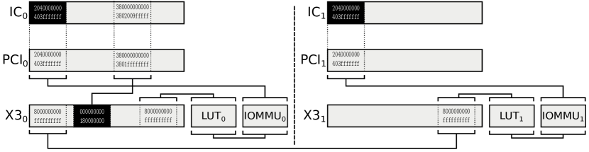
B.4.1 Model representation
definition "dram = (0x0000000000000000,0x000000203FFFFFFF)"
definition "pci = (0x0000380000000000,0x00003802009FFFFF)"
The Interconnect:
definition "node_0_m0_interconnect = empty_spec
acc_blocks := [dram],
map_blocks := [direct_map pci 2]
"
definition "node_1_m1_interconnect = empty_spec
acc_blocks := [dram],
map_blocks := [direct_map pci 3]
"
PCI Root Complexes:
definition "node_2_m0_pci = empty_spec
acc_blocks := [],
map_blocks := [direct_map dram 0, direct_map pci 2]
"
definition "node_3_m1_pci = empty_spec
acc_blocks := [],
map_blocks := [direct_map dram 1, direct_map pci 3]
"
Infiniband Cards (RDMA):
definition "remote_ram = (0x0000000000000000,0x000000203FFFFFF)"
definition "host_ram = (0x000800000000000,0x0008000203FFFFFF)"
definition "node_4_m1_cx3 = empty_spec
acc_blocks := [pci],
map_blocks := [block_map host_ram 6 0x0, block_map remote_ram 5 0x000800000000000]
"
definition "node_5_m1_cx3 = empty_spec
acc_blocks := [pci],
map_blocks := [block_map host_ram 7 0x0, block_map remote_ram 4 0x00080000000000]
"
MMUs:
definition "node_6_m1_tab = empty_spec
acc_blocks := [],
map_blocks := [],
overlay := Some 8
"
definition "node_7_m1_tab = empty_spec
acc_blocks := [],
map_blocks := [],
overlay := Some 9
"
IO-MMUs:
definition "node_8_m1_iommu = empty_spec
acc_blocks := [],
map_blocks := [direct_map dram 2]
"
definition "node_9_m1_iommu = empty_spec
acc_blocks := [],
map_blocks := [direct_map dram 3]
"
definition "sys = [(0, node_0_m0_interconnect),
(1, node_1_m1_interconnect),
(2, node_2_m0_pci),
(3, node_3_m1_pci),
(4, node_4_m1_cx3),
(5, node_5_m1_cx3),
(6, node_6_m1_tab),
(7, node_7_m1_tab),
(8, node_8_m1_iommu),
(9, node_9_m1_iommu)]"
\isadelimtheory
\endisadelimtheory\isatagtheoryend\endisatagtheory\isadelimtheory\endisadelimtheory
B.5 The Single Chip Cloud Computer
Intel’s single chip cloud computer (SCC [13]) is a 48-core research microprocessor consisting of 24 two-core tiles interconnected in a (x,y)-mesh with a 24 router network and hardware support for message-passing. We show the schema on Figure 6. On the chip there are four DDR3 memory controllers (MC) each of which is able to address 16GB of memory using physical address extensions (PAE) – 34-bit addressing mode. Therefore the SCC has a maximum memory of 64GB which exists on the SCC board. However, each core is able to access at most 4GB of at the same time.
Access to memory from each core is configured using a per-core system address lookup table (LUT). The LUT maps the core’s 32-bit physical addresses to the extended 46-bit system address. There are 256 entries in the table each of which translating a 16MB segment to any memory location e.g. DRAM, local message passing buffer (MPB), configuration registers of any tile. The LUT can be reprogrammed given a core has a valid mapping to the configuration space.
The lookup table is indexed by the bits 31..24 of the address, while bits 23..0 is the offset into the 16MB region. The lookup table will produce a 46-bit output address. Where bits 33..24 together with the offset are the 34-bit extended physical address. In addition, a tuple is out pot, that defines whether or not the router on the tile is bypassed, the destination tile ID and the port which should be used (identifies config registers, message passing buffer or memory controller)
The resources from the SCC are accessible from the host for initial bootstrap and communication later on. The interface supports IO and DMA transfers [16].
The single chip has a very simple interrupt system. Each core has a local APIC with the standard private timer. In addition, the LAPIC exhibits a memory mapped register that can be used to trigger one of its vectors by any core. There are no card specific interrupt sources that can be routed to the cores, neither exists there are any way of broadcasting an interrupt.
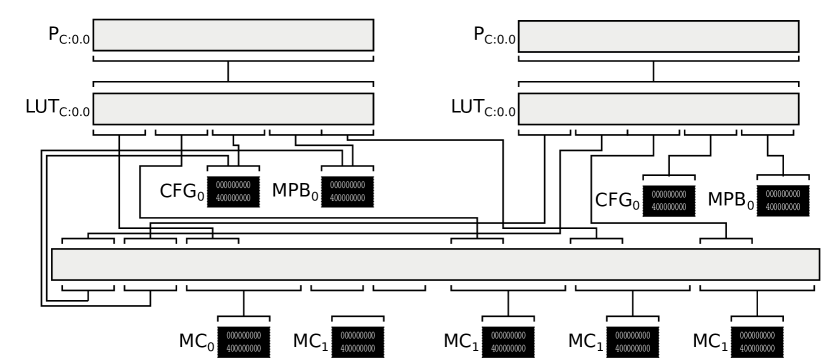
B.5.1 Model representation
Memory Controllers: 16GB each
definition "dram = (0x000000000,0x3FFFFFFFF)"
definition "node_mc = empty_spec
acc_blocks := [dram],
map_blocks := []
"
Local Memory / Message Passing buffer of 16kB
definition "lmb = (0x000, 0xFFFF)"
definition "node_lmb = empty_spec
acc_blocks := [lmb],
map_blocks := []
"
Local Configuration Registers
definition "conf = (0x000000, 0x7FFFFF)"
definition "node_conf = empty_spec
acc_blocks := [conf],
map_blocks := []
"
2D Mesh Network
definition "dram0 = (0x001800000000,0x001BFFFFFFFF)"
definition "dram1 = (0x00F000000000,0x0013FFFFFFFF)"
definition "dram2 = (0x041800000000,0x031BFFFFFFFF)"
definition "dram3 = (0x04F000000000,0x03F3FFFFFFFF)"
definition "conf_00 = (0x000800000000, 0x0008007FFFFF)"
definition "conf_01 = (0x002800000000, 0x0028007FFFFF)"
definition "mpb_00 = (0x000C00000000, 0x000c007FFFFF)"
definition "mbp_01 = (0x002C00000000, 0x002c007FFFFF)"
definition "sif = (0x00F400000000, 0x00F7FFFFFFFF)"
definition "node_0_interconnect = empty_spec
acc_blocks := [],
map_blocks := [block_map dram0 1 0x0, block_map dram1 2 0x0,
block_map dram2 2 0x0, block_map dram3 3 0x0,
block_map mpb_00 4 0x0, block_map mbp_01 5 0x0,
block_map conf_00 6 0x0, block_map conf_01 7 0x0,
block_map sif 44 0x0]
"
Core 0.0
definition "vram = (0x0000000, 0x0FFFFFF)"
definition "node_9_vas00 = empty_spec
acc_blocks := [],
map_blocks := [block_map vram 10 0x0 ]
"
definition "cpu_phys = empty_spec
acc_blocks := [],
overlay := Some 11
"
definition "lut00_cfg = (0x3000000, 0x3FFFFFF)"
definition "lut00_mpb = (0x1000000, 0x1FFFFFF)"
definition "node_11_lut00 = empty_spec
acc_blocks := [],
map_blocks := [block_map lut00_cfg 5 0x0, block_map lut00_mpb 6 0x0],
overlay := Some 0
"
Core 1.0
definition "node_12_vas01 = empty_spec
acc_blocks := [],
map_blocks := [block_map vram 13 0x0 ]
"
definition "lut01_cfg = (0x3000000, 0x3FFFFFF)"
definition "lut01_mpb = (0x1000000, 0x1FFFFFF)"
definition "node_14_lut01 = empty_spec
acc_blocks := [],
map_blocks := [block_map lut01_cfg 6 0x0, block_map lut01_mpb 7 0x0],
overlay := Some 0
"
definition "sys = [(0, node_0_interconnect),
(1,node_mc),
(2,node_mc),
(3,node_mc),
(4,node_mc),
(5,node_lmb),
(6,node_lmb),
(7,node_conf),
(8,node_conf),
(9, node_9_vas00),
(10, cpu_phys),
(11, node_11_lut00),
(12, node_12_vas01),
(13, cpu_phys),
(14, node_14_lut01)
]"
\isadelimtheory
\endisadelimtheory\isatagtheoryend\endisatagtheory\isadelimtheory\endisadelimtheory