Split, Send, Reassemble:
A Formal Specification of a CAN Bus Protocol Stack††thanks: Supported by the Defense
Advanced Research Projects Agency (DARPA) under agreement number FA8750-12-9-0179.
Abstract
We present a formal model for a fragmentation and a reassembly protocol running on top of the standardised CAN bus, which is widely used in automotive and aerospace applications. Although the CAN bus comes with an in-built mechanism for prioritisation, we argue that this is not sufficient and provide another protocol to overcome this shortcoming.
1 The CAN Bus Protocol
“A Controller Area Network (CAN bus) is a vehicle bus standard designed to allow microcontrollers and devices to communicate with each other in applications without a host computer.” 111http://en.wikipedia.org/wiki/CAN_bus (accessed February 23, 2017) Robert Bosch GmbH developed it in the 80s and published the latest release in 1991 [10].
The protocol is message-based and was designed specifically for automotive applications but is now also used in other areas such as aerospace, maritime and medical equipment. The CAN bus was designed to broadcast many short messages to the entire network. The broadcast mechanism provides data consistency in every node of the system. Typical information sent are sensor data, such as speed or temperature. Due to its simplicity, it is easy to implement; however, its capabilities are rather limited, in particular w.r.t. payload and security.
CAN Bus Limitations. In the CAN specification, version 2.0, there are two different message formats to send data in a (typical) CAN network [10]. The only difference between the two formats is that the standard frame format supports a length of 11 bits for the identifier, and the extended frame supports a length of 29 bits. The payload of both messages is 8 bytes only.222CAN-FD introduces frames with more than 8 bytes; but so far this extension of CAN has not been adopted by the industry.
CAN is a low-level protocol and offers no (standard) support for any security feature. Applications are expected to deploy their own security mechanisms. Failure to do so can result in various sorts of attacks. A lot of media attention was generated when cars were hacked and remotely controlled. The best security mechanism is to ensure that only trustworthy applications have access to the CAN bus. An alternative is the use of authentication and encryption, for instance through HMAC [8, 15] or GMAC [4].
The Need for Fragmentation and Reassembly. As soon as encryption and authentication is implemented, the messages used will be longer than 8 bytes; and even without encryption messages are often that long. Therefore there is the need for a fragmentation/reassembly protocol. In this paper we will present such a protocol on top of the CAN bus, which remains unchanged. One reason why we designed our own protocols is that they carry less overhead than off-the-shelf solutions.
The Need for Prioritisation. The CAN protocol comes with an in-built priority mechanism. It uses a bit-wise comparison method of contention resolution, which requires all nodes on the CAN bus to be synchronised at the point when transmission begins.
“The CAN specifications use the terms ‘dominant’ bits and ‘recessive’ bits where dominant is a logical […] and recessive is a logical […]. If one node transmits a dominant bit and another node transmits a recessive bit then there is a collision and the dominant bit ‘wins’. This means there is no delay to the higher-priority message, and the node transmitting the lower priority message automatically attempts to re-transmit six bit clocks after the end of the dominant message. This makes CAN very suitable as a real time prioritized communications system.”333https://en.wikipedia.org/wiki/CAN_bus (accessed February 23, 2017) A node that sent a recessive bit and detected a collision ceases transmission and will attempt a retransmission of its own message later on. Since CAN identifiers are unique for each message type and sender, and constitute the first part of any message, all but one nodes will stop while transmitting the CAN identifier.
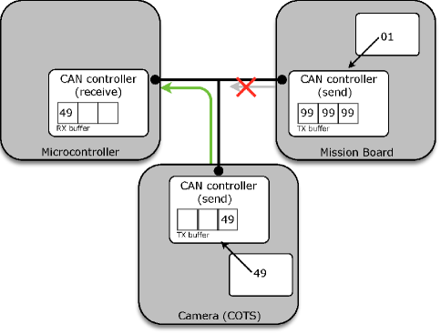
While this in-built priority mechanism works if CAN drivers and CAN controllers444 A node on a CAN bus is equipped with a CAN controller and a CAN transceiver. The CAN controller has a small number (typically 3) of TX buffers, where outgoing messages are stored before transmission, and a small number of RX buffers, which store incoming messages. The CAN transceiver manages the actual transmission of messages via the CAN bus—it normally sends the message of highest priority stored in a TX buffer first. The software that sends messages to the controller (which are then stored in the TX buffers), initiates the cancellation of messages, and requests messages received, is called a CAN driver. are considered only, it is not always sufficient due to the problem of priority inversion. We illustrate this by an example (cf. Fig. 1). Assume three nodes are attached to the CAN network: a mission board, a microcontroller and a camera—this is part of the architecture of our research vehicle (cf. Sect. 2).
Assume that the camera sends a constant stream of messages of medium priority—say with CAN ID . This message stream could be interrupted by a message of high priority, let say , which should be sent from the mission board to the microcontroller. Unfortunately, before this really important message is generated, another application on the mission board generates 3 absolutely unimportant message of low priority (here CAN ID ). They are transferred to the CAN controller and stored in the transmission (TX) buffer; they are scheduled to be sent via the CAN bus as soon as possible. Since there is a constant stream of more important messages (the ones stemming from the camera), these messages are never sent. As a consequence the high-priority message cannot be passed on to the TX buffer, and hence is stuck at the mission board.555Obviously this example could be avoided by having multiple CAN controllers on the mission board; but this cannot be guaranteed and often far more applications run on a single node than the number of CAN controllers available.
This example shows that there is need for another priority mechanism running on each node separately. Such a mechanism should retract one of the low-priority messages from the TX buffer of the mission board and replace this message with the high-priority one, which will be sent immediately; after that the low-priority message will be stored back to the buffer. There are two possible solutions for such a priority mechanism: (a) it could be integrated in the CAN driver, or (b) it is implemented as yet another protocol that works between the CAN driver and the fragmentation/application layer. We decided to implement the latter option to have a clear separation of concerns.
The protocol, called multiplexer and formally specified in Sect. 7, will be an interface between the CAN driver and several instances of the fragmentation protocol.
Our Contribution. We present a protocol stack to be used on top of the CAN bus, consisting of fragmentation and reassembly protocols, as well as a multiplexer. It has been formally modelled and partly analysed, implemented, and is successfully used in a research vehicle. The hardware as well as (the implementation of) the CAN bus protocol remains untouched; hence our protocol stack is ready to be deployed on any system featuring a CAN bus.
2 Our Research Vehicle
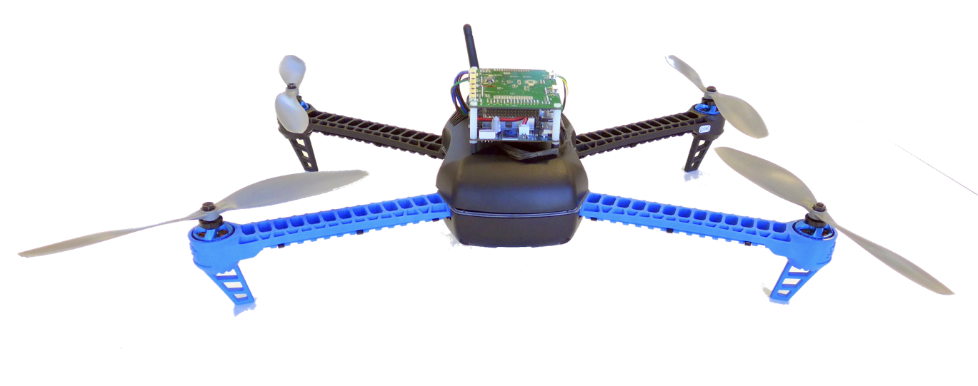
We use our protocol stack within a research vehicle, namely a small quadcopter. This off-the-shelf quadcopter with customised hard- and software was developed as part of the SMACCM (Secure Mathematically-Assured Composition of Control Models) project, a 4.5 year 18 million USD project funded to build highly hack-resilient unmanned aerial vehicles under DARPA’s HACMS (High-Assurance Cyber Military Systems) program. The team consists of formal verification and synthesis groups in Rockwell Collins, Data61 (formerly NICTA), Galois Inc, Boeing and the University of Minnesota.
Our quadcopter is equipped with two boards: a mission board and a control board. This architecture is artificially made more complex by adding a trusted gateway and an untrusted COTS (commercial off-the-shelf) component on the bus to introduce some of the complexities of larger air vehicles. One of the goals of the project is to show that even if an intruder gets hold of the COTS component, or of one of the untrusted applications running on the mission board (e.g. Linux), this will not invalidate essential security properties of the vehicle.
The use of the CAN bus for communication between the two boards and the COTS component (via the gateway) is a design decision based on the popularity of CAN in aviation and automotive applications. It shows that the use of CAN does not stand in the way of hack-resilience.
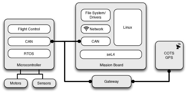
Fig. 3 (and in an abstract version also Fig. 1) shows a sketch of the vehicle’s architecture. The left hand side shows the flight controller, which is a pixhawk board with an ARM Cortex M4 CPU; it has direct connections to sensors and actuators. The mission board in the central part of Fig. 3 is more powerful: a TK1-SOM board with an ARM Cortex A15 CPU with virtualisation extensions running the seL4 microkernel for providing isolation in a mix of trusted and untrusted applications on top. The bottom and right-hand-side boxes in Fig. 3 show a gateway between the trusted part of the internal network on the left and the untrusted part of the internal network that connects to an unverified component on the right. The purpose of the gateway is to validate network packets from the right and only let through well-formed packets to allowed destinations.
The gateway is essential to achieve hack-resilience in the presence of untrusted components. Giving such components direct access to the CAN bus might give rise to denial-of-service (DoS) attacks: a hostile component might supply a continuous stream of high-priority packets, thereby inhibiting any other traffic. The gateway at least ensures that any message coming from a COTS component has a CAN identifier that labels it as such. The identifier gives the message a lower priority than safety critical messages from trusted components. Our multiplexer is designed to ensure that in these situations safety critical messages cannot be blocked by untrusted components. It is possible to entrust all security issues to the gateway. However, a simpler gateway need not investigate and restrict information flowing towards the COTS component; in this case safety critical messages that need to be kept private could be encrypted.
For the protocols presented in this paper and used in our research vehicle, we assume a functionally correct CAN bus. The proposed architecture and kernel-provided isolation on the mission board minimises the potential attack surface compared to standard systems. Messages that need splitting arrive from a ground station—which plans and manages missions—to the mission board and are forwarded to the microcontroller; the messages itself are often longer than 8 bytes, and when encrypted exceed definitely the payload of a standard CAN message.
3 Assumptions and Requirements
During the design of the fragmentation protocol we had to make some assumptions. All assumptions are realistic and can be assumed for our case study without loss of generality.
Assumptions on the CAN Bus.
-
1.
For the verification of two central correctness properties of the protocol—any message received has been sent, i.e. split messages are not reassembled in the wrong way, and any message sent is received—we assume a perfect channel and assume that every message sent via the CAN bus will be received by all nodes that are connected to the CAN bus. However, for our more basic correctness properties, such as the absence of deadlocks in protocol components or in the entire protocol stack, and the unreachability of error states, we do not make such an assumption.
-
(a)
The CAN protocol specifies an automatic retransmission of faulty messages after transmitting an error frame. Error frames may be sent by transmitting or receiving nodes. This happens on a lower protocol layer than the one modelled here.
-
(b)
In case resending of an entire message is needed (e.g. if fragments are lost), we leave this task to the application layer/user. The reason for this decision is that most information sent via the CAN bus is time-sensitive; so if the information is not sent immediately, it will be outdated. Examples are GPS-coordinates or telemetry data.
-
(a)
-
2.
We allow for the possibility that a CAN message is sent and received twice—possibly because one of the receivers used the error frame to ask for a resend. Our protocol is required to deal with such a repeated fragment.
-
3.
Messages sent over the CAN bus are not reordered. This is a realistic assumption. The CAN protocol sends one packet after the other; fragmented messages stemming from different sources may be interleaved, but reordering of messages sent by a single sender does not occur. Even if a packet is lost, the resending happens before the next frame is processed and sent.
A CAN controller allows overtaking of low priority messages by high priority messages by first offering the highest priority message stored in its TX buffers for transmission. The above assumption therefore only rules out reordering after messages have been transmitted on the CAN bus.
Requirements on the Input Data.
-
4.
Every message type, as determined by a CAN identifier (ID), has a unique sender.666Even if two applications would send messages of the same message type, one could use two different IDs. This requirement is reasonable and reflects the CAN protocol in the way it is used in the automotive industry. As a consequence it is impossible to have two senders sending messages with the same ID at the same time, and hence collisions are avoided.777The in-build priority messages will take care of messages with different IDs sent at the same time (see Sect. 1). By using wrong identifiers this requirement can be violated, yielding collisions and message loss. Thus it should be ensured that this requirement is satisfied.
-
5.
Every message we are going to split has a fixed length, determined by its message type. As a consequence we know in advance into how many fragments a message needs to be split. In case the message lengths can vary we assume that there is an upper bound and that shorter messages are extended by ‘dummy bits’.
Requirements for our Fragmentation Protocol.
-
6.
The distribution of the message IDs is fixed at compile time. We do not restrict the choice, as long as the assumption ‘unique sender for every message ID’ is maintained, and adjacent IDs are allocated to adjacent fragments of messages of the same type.
-
7.
We assume that the application layer, after submission of a message to an instance of the splitting protocol for transition over the CAN bus, will wait for an acknowledgement (positive or negative) before submitting a new message to that instance of the splitting protocol. The application layer may at any time submit a cancellation request for the last message submitted; this will speed up the (now likely negative) acknowledgement.
-
8.
Our protocol has to support legacy nodes. Independent of the software components we are adding (fragmentation protocol, authentication, encryption), the original CAN protocol should still be available and it must be possible to send and receive ordinary CAN messages.
Our fragmentation protocol uses a new CAN identifier for each fragment of each message type. One might wonder if this does not lead to a shortage of CAN IDs. Within our research vehicle this problem did not occur, and experts from the automotive side have ensured us that in typical applications there is an abundance of unused CAN IDs, in particular when using the extended frame format with 29-bit identifiers that allow over half a billion identifiers.
4 Related Work
Several fragmentation protocols to be deployed on top of the CAN bus have been developed in the past.
The ISO-TP [14] or ISO 15765-2 protocol is an international standard for sending data packets over a CAN bus that exceed the 8 byte maximum payload. ISO-TP splits longer messages into multiple frames, adding metadata that allows the interpretation of individual frames and reassembly into a complete message packet by the recipient. The protocol can handle message of up to 4095 bytes. The first fragment can only carry up to 7 bytes when using normal addressing, instead of the standard 8 bytes. Hence every message longer than 7 bytes should be split; as a consequence special care has to be taken so that this protocol can handle legacy messages.
Shin [11, 12] follows the spirit of ISO-TP and describes a protocol similar to ours. Due to his design the payload of each CAN message is split up into an 8-bit message identifier, a 7 bit sequence number, which points to the next fragment, and the actual payload, which has a maximum capacity of 6 bytes—2 bytes less than in original CAN frames and in our approach. As a consequence we have far less overhead than Shin’s approach. Moreover, his reassembling routine does not take packet loss into account.
The TP 2.0 protocol, sometimes also called VW TP 2.0, (see e.g. [13]) introduces a connection-oriented approach. It first sends a couple of messages to establish a “channel” between the sender and the recipients, then exchanges and sets up channel parameters such as the number of frames (fragments) to be sent, and finally transmits the message (by encoding the channel number into the CAN ID). Although the used CAN frames can use the full pay load of 8 bytes, the overhead lies in the setup-phase.
The Service Data Object (SDO) protocol,888http://www.can-cia.org/can-knowledge/canopen/sdo-protocol/ which is part of CANopen999http://www.can-cia.org/can-knowledge/canopen/canopen/ (see e.g. [5])—a communication protocol for embedded systems used in automation—also implements segmentation and desegmentation of longer messages. SDO is used for setting and for reading values from the object dictionary of a remote device. Because the values can be larger than the 8 bytes limit of a CAN frame, the SDO protocol implements also a fragmentation protocol. However, the fragmentation itself is a subprotocol and using SDO or even the entire CANopen infrastructure is again too much of an overhead.
All of these protocols bear a more or less heavy overhead w.r.t. the number of messages. Moreover, none of these solutions appear compatible with the priority mechanism offered by our multiplexer. In fact, adopting any of them stands in the way of inserting a multiplexer between the fragmentation protocol and the CAN driver, thus taking care of priority inversion, as we do here. Therefore, we designed our own simple protocol that exactly meets our needs; by using the vast amount of CAN identifiers available, our protocol does not have any overhead w.r.t. the number of messages sent.
5 Protocol Stack: Overall Structure and Informal Description
Before presenting our formal specifications, including formally defined data structures and unambiguous process-algebraic specifications, we describe the overall structure of our protocol stack, including all messages sent between components. By abstracting from formal details we discuss the ‘big picture’.
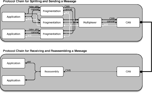
Figure 4 gives a schematic representation of our protocol stack. Every hardware component (node) contains exactly one instance of each of the two protocol chains. We distinguish 4 different layers.
-
•
The application layer: applications are components that send messages to and receive messages from the CAN bus (via the other 3 layers).
-
•
The CAN layer: this layer combines the CAN controller and the CAN driver. We will model a simple instance of this layer.
The remaining two layers connect the application with the CAN layer—they split and reassemble messages if necessary, and handle messages with high priority first.
-
•
The fragmentation/reassembly layer: the fragmentation protocol receives a message from an application, and, depending on the type of the message, simply forwards the message if it is a short or legacy, or otherwise splits the message into fragments of 8 bytes each. These fragments have the form of standard CAN messages and can (now) be sent via the CAN bus. The reassembly protocol receives such fragments that were sent via the CAN bus and forwarded by the CAN driver. It stores the fragments until a full message can be reassembled and transmitted to the application.
-
•
The multiplexer accepts messages from different instances of the fragmentation protocol (all running on the same hardware) and stores them in a priority queue. It always sends the message that needs to be transmitted next to the CAN driver, if necessary after cancelling a lower-priority message sitting in the TX buffer of the CAN controller. This prevents the blocking example of Sect. 1.
All these layers exchange information through message passing. In the remainder of the section we will discuss the different types of messages that occur in our protocol chain.
Protocol Chain for Splitting and Sending a Message. Any application is allowed to submit new messages . Every such message contains a message type and a payload. Depending on the type the message is sent to a particular instance of the fragmentation protocol. For this we assume that for each message type there is exactly one instance of the fragmentation protocol; an instance, however, is allowed to handle multiple message types, provided that they all stem from the same application. An application usually sends one new message at a time; in case a second packet is injected before the previous one has been fully handled, the protocol yields an error and deadlocks. To avoid this scenario the fragmentation protocol returns an acknowledgement message , informing the application that the handling of the message is finished—for each received exactly one is sent. The acknowledgement can be positive or negative, depending on whether the message was successfully sent via the CAN bus or not. The application has also the possibility to inject a -message to the fragmentation protocol, which will then stop handling the last message injected by the application, unless it is already finished with it.
The fragmentation protocol receives new messages from the application and splits them; the resulting CAN messages are passed on to the multiplexer. As in case of an application, the fragmentation protocol awaits an acknowledgement (positive or negative) before sending the next CAN message. In case the fragmentation protocol receives a cancellation request, it stops splitting a message, and in case the multiplexer has not yet acknowledged the last fragment submitted to it also informs the multiplexer about the cancellation request by sending it a -message. The multiplexer returns exactly one acknowledgement for each fragment received; it does not accept a second fragment from the same fragmentation instance before this has been sent. It accepts a cancellation request at any time.
The multiplexer schedules all messages received in an appropriate order (high priority messages first); the messages involved in this are again , , and . The CAN-messages that were sent by the multiplexer are handled by the CAN layer and end up in the TX buffer of the CAN controller, from where they are transmitted over the CAN bus.
Protocol Chain for Receiving and Reassembling a Message. After the messages were transmitted via the CAN bus, they are stored in the RX buffer of the CAN controller. The CAN layer stores and handles all incoming messages of type and forwards them to the reassembly protocol, which stores these messages—there is no pendant to the multiplexer in the receiving chain. As soon as a packet is fully received and reassembled, it is delivered to the appropriate application, using a message of type .
A formal specification of the multiplexer is presented in Sect. 7. Formal specifications of all the above-mentioned protocols are given in App. B. This includes the processes themselves, specified in the process algebra AWN (see below), as well as a detailed definition of the data structure involved.
6 AWN: A Specification Language for Protocols101010Parts of this section are published in [7].
Ideally, any specification is free of ambiguities and contradictions. Using English prose only—as is still state of the art in protocol specification—this is nearly impossible to achieve. The use of any formal specification language helps to avoid ambiguities and to precisely describe the intended behaviour. The choice of a specification language is often secondary, although it has high impact on the analysis.
For this paper we choose the modelling language AWN [6], which provides the right level of abstraction to model key protocol features, while abstracting from implementation-related details. As its semantics is completely unambiguous, specifying a protocol in such a framework enforces total precision and the removal of any ambiguity. AWN is tailored for modelling and verifying routing and communication protocols and therefore offers primitives such as unicast and multicast/groupcast; it defines the protocol in a pseudo-code that is easily readable—the language itself is implementation independent; and it offers some degree of proof automation and proof verification [3, 2], using Isabelle/HOL [9].
AWN is a variant of standard process algebras, extended with a local broadcast mechanism and a novel conditional unicast operator—allowing error handling in response to failed communications while abstracting from link layer implementations of the communication handling—and incorporating data structures with assignments; its operational semantics is defined in [6].
We use an underlying data structure (described in detail in App. B) with several types, variables ranging over these types, operators and predicates. First order predicate logic yields terms (or data expressions) and formulas to denote data values and statements about them. Our data structure always contains the types DATA, MSG, ID and of application layer data, messages, identifiers and sets of identifiers. The messages comprise data packets, containing application layer data, and control messages.
In AWN a network is modelled as a parallel composition of components. Here any party in the network that can be addressed as the recipient of a message is a component. On each component several processes may be running in parallel. Components communicate with their direct neighbours, which in our current application are all other components in the network.
The Process expressions are given in Table 1.
| process name with arguments | |
| choice between processes and | |
| conditional process: proceed as , but only if evaluates to true | |
| assignment followed by process | |
| broadcast message ms followed by | |
| multicast ms to all destinations dests | |
| unicast ms to dest; if successful proceed with ; otherwise with | |
| deliver data to application layer | |
| receive a message and store its contents in the variable msg | |
| process with initial valuation of its variables | |
| parallel valuated processes on the same component | |
| addressed component | |
| parallel composition of addressed components |
They should be understandable without further explanation; we add a short description in App. A.
7 A Formal Specification of the Multiplexer
In this section we present two out of four AWN-processes that entirely specify our multiplexer.
The Main Loop. The basic process MULTIPLEXERH (Process 9) receives messages from the fragmentation protocol or the CAN driver. Since the multiplexer is not always ready to receive messages, we equip the process with an in-queue (see App. B); so technically the multiplexer receives a message from this queue. MULTIPLEXERH maintains two data variables prio and txs. The former implements a priority queue which contains all CAN messages to be sent via the CAN bus; the later is a local storage which keeps track of the CAN IDs currently sent by or stored in the TX buffers of the CAN controller.
First, a message has to be received (Line 1). After that, the process MULTIPLEXERH checks the type of the message and calls a process that can handle this message: in case a CAN message is received from the fragmentation protocol, the process NEW_CANH is called (Line 4); in case of an incoming cancellation request the process CANCEL_CH is executed (Line 6); and in case a message from the CAN driver is read, the process ACK_CH is called (Line 8). In case a message of any other type is received, the process MULTIPLEXERH deadlocks; it is a proof obligation to check that this will not occur.
New CAN Message. In case a new CAN message is sent from an instance of the fragmentation protocol, the process NEW_CANH stores the CAN message and determines whether the newly received message is important enough to be forwarded directly to the CAN driver. The formal specification is shown in Process 10.
The received CAN message is first stored in the queue prio (Line 2), which contains all messages to be sent via the CAN bus. The protocol just stores the newly received message, it does not check for emptiness of . Therefore, to guarantee that no message is lost the property needs to hold before Line 2 is executed; it needs to be proven. The protocol then determines whether the message should directly be forwarded to the CAN driver—this is the case if the CAN ID is among the messages with lowest CAN IDs currently stored in prio (Line 4). Here equals the number of TX buffers available in the CAN controller. Lines 5–22 present all actions to be performed in case the message is forwarded to the CAN driver.
In case there exists an empty TX buffer , which is currently not used, the message should be sent to this TX buffer, and there is no need to erase a used TX buffer. The empty buffer is chosen in Line 6.131313Since is a free variable, it will be instantiated with a value that validates ; so the condition in the guard is satisfied iff . The CAN message is then forwarded to the connected CAN driver CH in Line 8. Since the CAN driver needs also the name of the TX buffer to be used, the value is sent next to the CAN message . The multiplexer also updates the local variable (Line 7), which keeps track of those CAN identifiers that are currently sent by or stored in the TX buffers. By this, the newly received message has been handled and the process can return to the main routine (Line 9).
In case all available TX buffers are used (Line 10), the least important message—the CAN message with the largest CAN ID—needs to be removed from the TX buffer and rescheduled later. This avoids the blocking example presented earlier. In Line 12 the process NEW_CANH determines the name of the TX buffer that contains the ‘worst’ message currently handled for sending. The CAN message that should be stored in this particular TX buffer cannot be put there immediately; a cancellation request needs to be sent first, and an acknowledgement needs to be received that informs the multiplexer about a free TX buffer. The routine checks whether a cancellation request was sent earlier, using the function . If this is the case, it returns straight to the process MULTIPLEXERH; otherwise a cancellation message is sent to the CAN driver CH, identifying the TX buffer that needs cancellation (Line 16).
8 Properties and Formal Analysis
After defining the splitting and reassembly protocol in a formal and unambiguous manner (including the multiplexer), we can now focus on verification tasks. A detailed analysis and verification is out of the scope of this paper—which concentrates on the necessity of the protocols and their formal specification. In this section we list a series of desired properties—a first analysis using model checking techniques indicates that these properties are satisfied.141414In fact we did find an error in the multiplexer that has been eliminated in the current version.
Unreachability of ERROR State. In our specification we use a special state ERROR that is reached by a component process whenever it receives an input that is unexpected, and for which no proper response in envisioned. As ERROR is not an AWN primitive, we proposed to simply implement it in terms of AWN primitives as a deadlock: .
Our first requirement on the correctness of the overall protocol is that none of its components will ever reach the ERROR state. Since the application layer is not part of our specification, we cannot show that it behaves properly. Instead, we have to formulate a requirement on the communications between the application layer and our protocol; we only require the unreachability of ERROR under that condition.
The Protocol is Deadlock Free. Another requirement is that our protocol is deadlock free, in the sense that each reachable state has an outgoing transition. As termination of our protocol is not envisioned, a deadlock is a clear case of undesirable behaviour. This requirement does not rule out any state where no further activity occurs due to lack of input from the application layer, for the possibility of such input is modelled as an outgoing transition.
Each Component of the Protocol is Deadlock Free. A related requirement is that each component in our specification is deadlock free. The components are all instances of the fragmentation protocol, the multiplexer, the CAN receiver, the CAN sender, and the reassembly protocol. Optionally, the input queue of the multiplexer can be regarded a separate component, too.
This requirement is neither weaker nor stronger than the above requirement that the entire protocol is deadlock free, for it could be that a deadlock of the entire protocol occurs when two components fail to properly communicate, even though each of them could make progress if only the other one cooperated.
Any Message Received Has Been Sent. Here a message counts as ‘sent’ when it is submitted by the application to the fragmentation protocol; it counts as ‘received’ when it is passed on by the reassembling protocol at each node listed as a destination of the message to the corresponding application layer.
This requirement is definitely violated in case our reassembly protocol reassembles messages the wrong way. Such a situation can occur in case of message loss on the CAN bus.
For this reason, we can only hope to establish the property under the condition that no message loss occurs. In our model, this is quite simple, as the possibility of message loss is not modelled. This follows the advice of experts on the CAN bus, saying that any message that is actually sent from a TX buffer at the transmitting end is always picked up by a RX buffer at the receiving end.
Any Message Sent Is Received. This may be regarded as the central requirement of the protocol. In fact, some of the requirements above are in some sense entailed by this requirement, as the presence of deadlocks will surely manifest itself as failure to handle and receive further messages.
Obviously, this requirement cannot be guaranteed if there is message loss on the CAN bus. Thus, as before, we assume that no loss on the CAN bus occurs. Since the CAN bus handles higher priority messages in preference to lower priority messages, a given message that is submitted to the protocol by the application layer at a node may never be selected by the CAN bus if a steady stream of higher-priority messages is send by another node; so this property does not hold. Consequently, further the assumption that there is no steady stream of higher priority messages is required.
The property is also violated if the input queue of the multiplexer is grossly unfair, in the sense that it has no time to accept a message from one of the fragmentation processes because it is continuously busy accepting incoming messages from other fragmentation processes on the same node. Since the input queue of the multiplexer is an order of magnitude faster than the CAN bus, there should be no situation where there is contention in getting into that queue.
One of the main dangers faced by the CAN bus and its surrounding protocols is a Denial of Service (DoS) attack. In our application (see Sect. 2), we protect the bus against DoS attacks by giving only trusted software access to a (secure) CAN bus. Unsecure components may also send messages to the bus, but those message first pass through a trusted gateway, which performs rate limiting.
The proof of this requirement will undoubtedly be the hardest part of the verification effort. It probably requires various intermediate results, such as ‘every fragment sent by a fragmentation process is received by the reassembly process on each of its destination nodes’.
Buffers Have a Maximal Length. Our formal specification employs message buffers in two places. One is (in) the CAN receiver; the other is the input queue of the multiplexer. Both buffers are modelled as FIFO queues. Following the specification both have unbounded capacity. In reality, buffers have a bounded capacity, and overflows will occur when trying to exceed it.
For the CAN receiver an upper bound cannot be given without a timing analysis comparing the capacity of the CAN bus and the ‘working speed’ of the reassembly protocol.
The input queue of the multiplexer, on the other hand, has a maximal length. To calculate this length, we add the maximal number of messages it could receive from any fragmentation process, times the number of fragmentation processes running on the node, plus the maximum number of message received from the associated CAN controller. For each type of message we calculate an upper bound.
The Application Layer Can Always Succeed in Submitting a New Message. A requirement mentioned above guarantees that, under certain conditions, messages submitted will eventually reach their destinations. As a liveness property for the application layer, this is only convincing if in addition the application layer can always succeed in submitting to the fragmentation protocol any message its want to transmit.
9 Conclusion and Future Work
In this paper we have presented a formal and unambiguous specification of a fragmentation and reassembly protocol, as well as a multiplexer. These protocols are running on top of a standard CAN bus and hence can directly be applied in many areas such as the automotive space. We have argued why both protocols are needed in real applications; and have shown applicability by running our protocols on a research quadcopter.
Last but not least we have listed a couple of important properties our protocol stack should satisfy. It is our belief that the presented properties do hold for our formally specified protocols, at least under some assumptions (as we have pointed out). Future work could provide formal proofs for these properties.
References
- [1]
- [2] T. Bourke, R.J. van Glabbeek & P. Höfner (2014): A mechanized proof of loop freedom of the (untimed) AODV routing protocol. In F. Cassez & J.-F. Raskin, editors: Automated Technology for Verification and Analysis (ATVA ’14), LNCS 8837, Springer, pp. 47–63, 10.1007/978-3-319-11936-6_5.
- [3] T. Bourke, R.J. van Glabbeek & P. Höfner (2016): Mechanizing a Process Algebra for Network Protocols. Journal of Automated Reasoning 56(3), pp. 309–341, 10.1007/s10817-015-9358-9.
- [4] M.J. Dworkin (2007): Recommendation for Block Cipher Modes of Operation: Galois/Counter Mode (GCM) and GMAC. NIST Special Publication 800-38D, National Institute of Standards and Technology (NIST), U.S. Department of Commerce, 10.6028/NIST.SP.800-38D.
- [5] K. Etschberger (2001): Controller Area Network: Basics, Protocols, Chips and Applications. IXXAT Automation GmbH.
- [6] A. Fehnker, R. J. van Glabbeek, P. Höfner, A. K. McIver, M. Portmann & W. L. Tan (2012): A Process Algebra for Wireless Mesh Networks. In H. Seidl, editor: European Symposium on Programming (ESOP ’12), LNCS 7211, Springer, pp. 295–315, 10.1007/978-3-642-28869-2_15.
- [7] R.J. van Glabbeek, P. Höfner, M. Portmann & W.L. Tan (2016): Modelling and Verifying the AODV Routing Protocol. Distributed Computing 29(4), pp. 279–315, 10.1007/s00446-015-0262-7.
- [8] H. Krawczyk, M. Bellare & R. Canetti (1997): HMAC: Keyed-Hashing for Message Authentication. RFC 2104 (Informational, Errata Exist). Available at http://tools.ietf.org/html/rfc2104.
- [9] T. Nipkow, L. C. Paulson & M. Wenzel (2002): Isabelle/HOL — A Proof Assistant for Higher-Order Logic. LNCS 2283, Springer, 10.1007/3-540-45949-9.
- [10] Robert Bosch GmbH, Stuttgart, Germany (1991): CAN Specification, Version 2.0. Available at http://www.bosch-semiconductors.de/media/ubk_semiconductors/pdf_1/canliteratur/can2spec.pdf.
- [11] C. Shin (2014): A framework for fragmenting/reconstituting data frame in Controller Area Network (CAN). In: International Conference on Advanced Communication Technology (ICACT ’14), IEEE, pp. 1261–1264, 10.1109/ICACT.2014.6779161.
- [12] C.M. Shin, T.M. Han, H.S. Ham & W.J. Lee (2010): Method for Transmitting/Receiving Data Frame in CAN Protocol. Available at http://www.google.com/patents/US20100158045. US Patent App. 12/543,876.
- [13] C. Sommer & F. Dressler (2015): Vehicular Networking. Cambridge University Press, 10.1017/CBO9781107110649.
- [14] International Organization for Standardization (2011): Road Vehicles – Diagnostic Communication Over Controller Area Network (DoCAN) – Part 2: Transport protocol and network layer services. ISO 15765-2:2011(en), ISO. Available at http://www.iso.org/iso/home/store/catalogue_ics/catalogue_detail_ics.htm?csnumber=54499.
- [15] S. Turner & L. Chen (2011): Updated Security Considerations for the MD5 Message-Digest and the HMAC-MD5 Algorithms. RFC 6151 (Informational). Available at http://tools.ietf.org/html/rfc6151.
Appendix A Informal Description of the Process Expressions of AWN
In this appendix we describe the Process expressions, given in Table 1.
A process name comes with a defining equation
where is a process expression, and the are data variables maintained by process . A named process is like a procedure; when it is called, data expressions of the appropriate type are filled in for the variables . Furthermore, is a condition, an assignment of a data expression exp to a variable var of the same type, dest, dests, data and ms data expressions of types ID, , DATA and MSG, respectively, and a data variable of type MSG.
Given a valuation of the data variables by concrete data values, the process acts as if evaluates to true, and deadlocks if evaluates to false.151515As operators we also allow partial functions with the convention that any atomic formula containing an undefined subterm evaluates to false. In case contains free variables that are not yet interpreted as data values, values are assigned to these variables in any way that satisfies , if possible. The process acts as , but under an updated valuation of the data variables. The process may act either as or as , depending on which of the two is able to act at all. In a context where both are able to act, it is not specified how the choice is made. The process broadcasts (the data value bound to the expression) ms to all connected components, and subsequently acts as , whereas the process tries to unicast the message ms to the destination dest; if successful it continues to act as and otherwise as . We abbreviate by ; this covers the case where the subsequent behaviour after the unicast is independent of its success. The process tries to transmit ms to all destinations dests, and proceeds as regardless of whether any of the transmissions is successful. The process receives any message (a data value of type MSG) either from another component, from another process running on the same component or from an application layer process connected to that component. It then proceeds as , but with the data variable bound to the value . In particular, models the injection of data from the application layer, where the function generates a message containing the application layer data and the identifier id, here indicating the message type. Data is delivered to the application layer by deliver.
The internal state of a sequential process described by an expression in this language is determined by , together with a valuation associating data values to the data variables var maintained by this process. In case a process maintains no data values, we use the empty valuation . A valuated process is a pair of a sequential process and an initial valuation .
Finally, denotes a parallel composition of valuated processes and , with information piped from right to left; in typical applications [7] is a message queue. This yields a component expression.
In the full process algebra [6], node expressions are given by component expressions , annotated with a component identifier id and a set of nodes that are connected to id. In the current application we do not encounter cases were components send messages to other components that are not connected. As a consequence, the annotation occurring in node expressions is of no significance, and omitted. We speak instead of addressed component expressions . In our application is for example a specification of a generic CAN driver, whereas denotes a specific CAN driver occurring in the system, such as the one on the mission board. The identifier id of this driver is used as an address by components that send messages to this driver.
A network is modelled as a parallel composition of addressed component expressions, using the operator .
In our specification, we will use a process ERROR, representing a state that needs to be avoided at all costs. Showing that this state is in fact unreachable ought to be part of a verification effort. When specifying a part of a system (as we do in this report) we make assumptions on the behaviour of components outside our specification that communicate with our part. The ERROR state may be reachable if those external components violate the assumptions. Hence, showing that ERROR is unreachable involves verifying aspects of the correctness of these external components. Formally, we define ERROR as a process name with defining equation , representing a deadlock.
Appendix B Formal Specification of all Protocols
The following sections will present formal specifications of all the above-mentioned protocols. This includes the specifications themselves, given in AWN, as well as a detailed definition of the data structure involved. As the semantics of AWN is completely unambiguous, specifying a protocol in such a framework enforces total precision and the removal of any ambiguity.
B.1 Data Structure: Mandatory Types and Messages
In this section we set out the basic data structure needed for the detailed formal specification of our fragmentation protocol. As well as describing types for the information handled at the nodes/components during the execution of the protocol we also define functions which will be used to describe the precise intention—and overall effect—of the various update mechanisms in our protocol.
B.1.1 Components
In our formalisation of the CAN bus we consider a finite set of hardware components; in Fig. 1 these are the microcontroller, the mission board, and the camera. The defining characteristic of this set is that there is exactly one CAN driver for each hardware component . The COTS component does not count, as it only partakes to the trusted CAN bus via the gateway (cf. Fig. 3).
Furthermore, we consider a finite set of applications. Each application is a party that sends messages via the CAN bus. An application is located on a hardware component, and on each hardware component can be multiple applications. Figure 4 shows two hardware components, each with two applications.
Finally, there is a finite set of CAN software components—the white rectangles of Fig. 4. Each of them will be specified by an addressed component expression as defined in App. A. In our model a CAN driver is modelled as the parallel composition of two software components: one dealing with transmission, and one with receipt of CAN messages.
B.1.2 Mandatory Types
The process algebra AWN always requires the following data structure: application layer data, messages, component identifiers and sets of component identifiers.
-
1.
The ultimate purpose any communication protocol is to deliver application layer data. The type describes a set of application layer data items. An item of (encrypted) data is thus a particular element of that set, denoted by the variables . Since we also inform the application layer about progress, we add special strings such as “message successfully sent” to the set DATA. Moreover, the empty data string is denoted by .
-
2.
Messages are used to send information via the network. In our specification we use the variable of the type . All message types will be described below.
-
3.
The type describes a set of identifiers. In our application it is the disjoint union of a set of application identifiers (exactly one for each application from ), a set of component identifiers (exactly one for each software component from ) and a set of CAN IDs. Moreover, we use a set of message types, which we assume to be a subset of . For each hardware component , the constants , and of type denote the identifiers of the unique multiplexer, reassembly protocol, and transmitting CAN driver within . The variable ranges over and indicates the (ultimate) sender of a message—an application. The variables , range over ; and and over . Finally we make use of a special element , denoting the absence of a message.
A message sent over the CAN bus is normally only a fragment of a larger message (stemming from the application layer), although we allow for CAN messages that are not fragmented. Henceforth, we use the word fragment for such a message. Message types are allocated to entire messages, whereas CAN IDs are allocated to fragments. A CAN ID determines the message type of the whole message, as well as the fragment counter indicating which fragment of it is currently been transmitted. A message type uniquely determines the sender of the message, the set of recipients, and the number of fragments into which the message is split. Here we take as an initial segment of the natural numbers. In our implementation, 11 bits are reserved for CAN IDs. Given a message type that calls for fragmentation into 3 parts, the CAN IDs form an interval such as 52–54. The message type is then simply denoted by the first element of this interval; in the example 52. It is in this sense that . We use an injective partial function
that, given a message type mt and a fragment counter , which is no larger than the number of fragments for messages of type mt, returns a CAN ID. In our example, . Due to injectivity, if is defined, the values and can be retrieved. For the implementation of the protocol, this function is implemented as a static table, stored at each component. Sometimes it is possible to reduce the size of this table since only those messages types have to be specified that are actually sent or received by the fragmentation and reassembly protocols.
B.1.3 Messages
Messages are the main ingredient of all our protocols and are used to distribute information. The message types used range from new messages to be split and injected by the application layer, via messages to acknowledge successful sending, to actual CAN messages that are sent via the CAN bus. To generate theses messages, we use functions
A message is of type mt and has the payload d. It is injected by the application and received by the fragmentation protocol, which, if necessary, then splits the message into smaller fragments.
A reassembled message which is returned to an application by the reassembly protocol is given by , where mt and d are again the message type and the actual data, respectively.161616 does not generate a message, but is of type . The reason is that, in AWN, messages are used to send information to software components. Since we do not model the application, is a message delivered to the environment, which has to be of type .
The function generates a CAN message with CAN ID cid, containing the data d. By a fragmented CAN message is obtained, containing the data d and the CAN ID . This message is the fragment of a message of type mt; we abstract from all other details of such a CAN message.
The functions and are used to request the cancellation of a message sent before. The only difference between these two are that the former tries to cancel the last message sent, whereas the latter requests the cancellation of a CAN message with CAN ID cid.
The acknowledgement message generated by is used to communicate the status of a message. is a Boolean value: indicates that the message or fragment was sent successfully, whereas indicates failure, which either stems from a sending problem (e.g. a hardware failure) or from the message being successfully cancelled.
The last function we use to generate messages is . It is essentially a wrapper function that takes an arbitrary message as input and returns the same message with an additional variable attached— the identifier of a transmit (TX) buffer (an element of the set of TX buffer identifiers).171717A more detailed description of the TX buffers is given in Sect. B.5.1.
We assume that all functions building messages are injective, so that for example the values mt and data can be retrieved from . Likewise, we can distil the message type mt, the fragment number no and the payload d from .
B.1.4 Message Type Table
Information about the sender, the potential destinations, the length, and the identifier of the corresponding instance of the fragmentation protocol for each and every CAN message are stored in a static table. All components have access to a copy of this table.181818Of course, when implementing the protocol, each node would only store the bits of the table that are actually needed by the node. Such an information table is defined as a set of entries, exactly one for each message type.
Formally, we define the identifier table as a (total) function
Here identifies for every CAN ID cid (and hence for every message type) its (unique) sender , a list of receivers , the number parts of CAN messages into which the (entire) message needs to be split, and the unique identifier fid of the fragmentation protocol handling the CAN message. Since we assume that the length of any message of a given type is fixed, this number can easily be determined. Note that is total; hence always returns a value. We use projections to select the corresponding component from the -tuple.
In the formal model (and indeed in any implementation) we need to extract information form id_tab. To this end, we define the following functions.
-
1.
The sender of a message with CAN ID cid:
-
2.
The set of potential (allowed) receivers of a message with CAN ID cid:
-
3.
The number of CAN messages into which a message with CAN ID cid is split:
In case no splitting is needed, e.g., if the message is a legacy message, and the message should be handled as standard CAN message, fragments should be set to . This guarantees backwards compatibility of our protocol.
-
4.
The name of the instance of the fragmentation protocol responsible for handling the message:
The value only depends on the message type of a message with CAN ID cid; hence for every .
B.2 The CAN Driver
In this section, we present a formal specification of the CAN driver, using the process algebra AWN. The presented driver is pretty simple and puts messages received straight into the corresponding TX buffer. In particular it does not provide a message queue to store messages until they are handled. Such a queue is not needed since it is part of the multiplexer, which we will present later.
The overall structure of the CAN driver—sketched in Fig. 5—consists of two independent components that do not interact. The first handles message sending, the second message receipt.
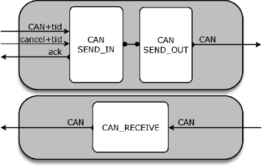
-
•
The protocol that handles message sending is split into two processes: the first process, called CAN_SEND_INH is able to receive messages from the multiplexer. These messages are either CAN messages or cancellation messages—both contain a TX-buffer identifier tid. If a CAN message is received, it is stored in the corresponding TX buffer, and the process CAN_SEND_OUTH is called, which subsumes the behaviour of CAN_SEND_INH and also handles the message sending. If a cancel-message is received, the process erases the corresponding TX buffer.
-
•
The protocol that handles message receipt is a single process . It models a simple queue, which stores all incoming messages and forwards them to the reassembly protocol as soon as that protocol is ready to handle the next message.
All these processes are parametrised with the name of the hardware component on which the CAN driver is located.
B.2.1 Data Structure
Each CAN controller provides a number of transmit (TX) buffers. Each buffer is able to store a complete CAN message for transmission over the CAN bus. Our architecture offers 3 TX buffers on the microcontroller, and one on the mission board; both boards offer 2 receive (RX) buffers.191919The second RX buffer, however, should not be used due to a hardware bug. We assume that every TX buffer on a board has a unique identifier—the set of all identifier is .
We abstract from the concrete number of buffers, and model the buffers as a (total) function of type . If the TX buffer identified by tid stores a message msg, then ; to indicate that the buffer is empty, we use the special element . We define the function space of all these functions as
In our formal specifications we often use an assignment to change a particular value of a function, e.g. (Line 4 of Process 1). Implicitly this states that all other values stay the same.
The CAN driver is supposed to send the message of highest priority (with lowest CAN ID) next. To this end we define a partial function
that determines the TX buffer that contains this CAN message that is most urgent; in case there are different messages with the same priority it chooses non-deterministically. We claim that the function best is actually deterministic in our setting. Formally the function is required to satisfy
Note that is undefined if and only if all TX buffers are empty, i.e., if for all .
We use a queue-style data structure for modelling an inbox of the CAN receiver. In general, we denote queues of messages by , denote the empty queue by , and make use of the standard (partial) functions , and that return the “oldest” element in the queue, remove the “oldest” element, and add a packet to the queue, respectively.
In our protocol specification below, all messages received via the CAN bus are stored until the reassembly protocol is ready to handle them. This may not be needed in the implementation of this protocol, as a timing analysis may show that when a message arrives, the protocol is always ready to handle it. However, in the forthcoming verification of the correctness of our protocol we do not want to depend on this timing analysis, and hence incorporate incoming message queues. Thus, a separate verification—involving the timing analysis—will be needed to show that these queues can be omitted.
At the moment we assume an infinite queue, which is unrealistic. It is an easy task to model a finite queue, where messages are lost in case the buffer is full. Of course then properties such as “every message sent will be received” may not hold; they require carefully designed preconditions.
This section concludes with a table summarising the entire data structure we use for the CAN driver. It summarises not only the data structure presented in this section, but also recapitulates the necessary part of the structure presented in Sect. B.1. Similar tables will be given at the end of every section that discusses data structure (cf. Sections B.3.1, B.4.1 and B.5.1).
| Basic Type | Variables | Description |
| MSG | msg | messages |
| DATA | data | data/payload of messages |
| TX | tid | identifiers for TX buffers |
| CID | cid | CAN IDs |
| SID | CAN software component identifiers | |
| Complex Type | Variables | Description |
| buffer | array of (CAN) messages, modelling the TX buffers | |
| msgs | message queues | |
| Constant | Description | |
| special message symbol (indicating absence of a message) | ||
| empty queue | ||
| multiplexer identifier for hardware component | ||
| reassembling protocol identifier for hardware component | ||
| transmitting CAN driver identifier for hardware component | ||
| receiving CAN driver identifier for hardware component | ||
| Function | Description | |
| cancellation message | ||
| acknowledgement to multiplexer | ||
| create CAN messages out of identifier and payload | ||
| wrapper function to add a TX-identifier to a message | ||
| set of potential (allowed) receivers of a message | ||
| returns the name of the TX that contains the ‘best’ CAN message | ||
| returns the ‘oldest’ element in the queue | ||
| removes the ‘oldest’ element in the queue | ||
| inserts a new element into the queue | ||
B.2.2 Formal Specification
Sending Messages. The sending procedure consists of two different processes. The first solely deals with receiving messages (from the multiplexer); and the second also with sending messages on the CAN bus. The second process subsumes the behaviour of the first process by offering it as a alternative to sending. The first process is only called in the initial state of the protocol, and as a potential behaviour of the second process. Both processes maintain a single variable , which models the corresponding TX buffer (see above).
The first process, named CAN_SEND_INH and depicted in Process 1, starts with receiving a message from the connected multiplexer (Line 1). After that the process checks the type of the message received:
In case the message is a CAN message with an additional value , which indicates the destined TX buffer, the process stores the message into the TX buffer (Line 4) and calls the process CAN_SEND_OUTH, which handles the sending of CAN messages, as well as the processing of further messages from the multiplexer (by calling CAN_SEND_INH). Note that the new message is copied into the TX buffer regardless whether the buffer already contains a message. If it does, that previous message is lost. It is up to the multiplexer (Sect. B.5) to avoid such a scenario.
In case the process receives a cancellation request for TX buffer (the incoming message has the form , Line 6), depending on the status of the corresponding TX buffer, different actions are performed. If buffer is empty (Line 8) there is no message to be cancelled and the protocol performs no action; it calls the process CAN_SEND_OUTH to proceed. If the buffer is not empty (Line 10) the process erases the buffer. After that the multiplexer is informed about the successful cancellation, which is done by unicasting the message to the connected multiplexer MH. Since our unicast is blocking (the protocol is stuck if the recipient of the message is not ready to receive the message), there could be a possibility that the protocol deadlocks while trying to send the acknowledgement. To prevent this, we make sure that the multiplexer is input enabled, meaning that the multiplexer is always ready to receive messages (cf. Sect. B.5).
In case another type of message would be received the protocol deadlocks after message receipt. However, we can show that no other message type can be received and hence the protocol is free of deadlocks.
The main purpose of the second process, named CAN_SEND_OUTH and depicted in Process 2, is to send the CAN messages stored in the TX buffers. It also offers the behaviour of CAN_SEND_INH, to process another incoming message as an alternative to any activity that could block further progress.
If there is another incoming message, the process may run CAN_SEND_INH (Line 1); otherwise CAN_SEND_OUTH determines the CAN message that should be send next (if any). This is done by use of the function in Line 2. Since best returns the name of a TX buffer that contains a CAN message202020In fact an invariant we might need to show is that all TX buffers only contain CAN messages. the second conjoint is not a restriction—it is used to distil the CAN ID of that message.
In Line 6 the process sends the CAN message with highest priority to the intended recipients of this message, which are determined by the function . This transmission uses the CAN bus and is carried out by the CAN controller. It will succeed only when there are no CAN messages with higher priority sent by other CAN controllers on the bus. As long as the transmission is pending, the process has the option to process another incoming message by executing CAN_SEND_INH (Line 4). After the message has been successfully sent via the CAN bus, the TX buffer is erased (Line 7) and the connected multiplexer is informed about success by an ack-message (Line 8). As remarked before, the multiplexer is always ready to accept this acknowledgement. Finally, the process returns to CAN_SEND_OUTH to either accept another incoming message from the multiplexer or to transmit another buffered message on the CAN bus.
Line 4 guarantees that the process can receive another message (via Line 1 of Process 1). Without this line Process 2 can give rise to stagnation (deadlock), since the groupcast-action of Line 6 can only succeed if the CAN bus is not busy sending higher-priority messages from other nodes.
Receiving Messages. We assume that any message sent via the CAN bus is actually received by all CAN controllers/drivers that are supposed to receive the message. For this reason, a CAN driver should always be able to perform a receive action, regardless of which state it is in. We introduce a process (see Process 3), modelling a message queue, that runs in parallel with CAN_SEND_INH/ CAN_SEND_OUTH. Every incoming message is stored in this queue, and piped from there to the reassembly protocol RASSH, which we will discuss later in Sect. B.4, whenever RASSH is ready to handle a new message. The process CAN_RECEIVEH is always ready to receive a new message.
Similar to the process call in Process 2 the receive-action in Line 8 is needed to guarantee that messages can be received at any time.
B.2.3 Initialisation
To finish our specification, we have to define an initial state for the CAN driver. The initial state requires the assignment of any variable occurring in a process. Such an assignment is provided by valuation functions, offered by AWN (cf. App. A).
The initial process of the CAN driver on hardware component is given by the expression
with and the component identifiers of the sending and receiving CAN components, and with
This says that initially all TX buffers controlled by a CAN driver are empty, and the message queue of CAN messages received by a CAN receiver is empty.
B.3 Fragmentation Protocol
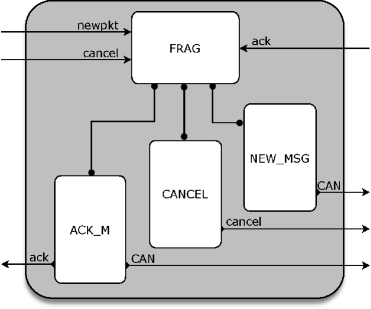
In this section, we present a formal specification of the fragmentation protocol. Our model, which is sketched in Fig. 6, consists of 4 processes, named FRAGH, NEW_MSGH, CANCELH and ACK_MH:
-
•
The basic process FRAGH receives a message from the application layer or from the multiplexer and, depending on the type of the message, calls other processes. When there is no message handling going on, it idles until a new message arrives.
-
•
The process NEW_MSGH describes all actions performed by the fragmentation protocol when a new message is received from the application. This includes the possibility of reaching an unrecoverable error state in case the application injects a message before a previous message was successfully handled or cancelled. The application layer should be programmed in such a way that this error state is always avoided.
-
•
The process CANCELH handles all actions to be performed when an application request the cancellation of a message previously sent.
-
•
The process ACK_MH describes the protocol behaviour in case an acknowledgement message (positive or negative) is received from the multiplexer. Depending on the situation, this process reports the status to the application, sends the next fragment, or reaches an unrecoverable error state.
B.3.1 Data Structure
The main intention of the protocol is to split data given from the application layer. For this purpose we define functions to manipulate data. Since all these functions can be seen as bit-level operations, we are not giving the exact definitions.
The function extracts the first bytes from a given data; or returns the entire data in case it is shorter.
The function is the complement of and returns the remaining data (if any) after bytes have been chopped off.
The following table summarises the entire data structure we use for the fragmentation protocol.
| Basic Type | Variables | Description |
| MSG | msg | messages |
| DATA | data, ndata | stored data |
| no | fragment counter | |
| abort, suc | Boolean flags | |
| MT | mt, nmt | message types |
| CID | CAN IDs | |
| SID | CAN software component identifiers | |
| Constant | Description | |
| the empty data string | ||
| special message type symbol, denoting undefined message type | ||
| multiplexer identifier for hardware component | ||
| Function | Description | |
| creates application-layer message out of message type and data | ||
| cancellation message from application layer | ||
| cancellation message to multiplexer | ||
| acknowledgement from multiplexer | ||
| create CAN messages out of identifier and payload | ||
| returns a CAN ID for a given message type and a fragment counter | ||
| takes the first bytes from a given data streams | ||
| removes the first bytes from a given data streams | ||
| number of CAN messages into which a message is split | ||
B.3.2 Formal Specification
The Main Loop. The basic process FRAGH receives messages from the application layer or the multiplexer; one at a time. This process maintains four data variables mt, data, no, and abort, in which it stores the message type last handled, the data received from the application and not yet fragmented, the number of fragments already sent, and a flag to signal that the application requested cancellation. The process is considered to be currently handling an application-layer message iff the value of is non-zero.
The routine is formalised in Process 4. First, a message has to be received using the command receive (Line 1). The message stems either from the application or from the multiplexer (cf. Sect. 5). After that, the process FRAGH checks the type of the message and calls a process that can handle this message: in case of a ‘fresh’ message from the application layer, the process NEW_MSGH is called (Line 4)—note that during the process call the values of and are updated with the new values and extracted from the message; in case of an incoming cancellation request the process CANCELH is executed (Line 6); and in case a message from the multiplexer () is read, the process ACK_MH is called, carrying the Boolean flag suc received from the multiplexer. In case a message of any other type is received, the process FRAGH deadlocks; it is a proof obligation to check that this will not occur.
New Message. The process NEW_MSGH describes all actions performed by the fragmentation protocol when a new message is injected by an application hooked up to the instance of the fragmentation protocol.
In case the fragmentation protocol is in the process of sending (fragmenting) a message, which was previously received, the value of is different to , since this integer counts the number of fragments already sent. If this is the case (Line 1), the process deadlocks with an error; the entire fragmentation stops and cannot be restored. It is up to the application hooked up to the fragmentation protocol to avoid this scenario.
In case the fragmentation protocol is not handling another message (), the process NEW_MSGH starts splitting the data: it chops off the first bytes of data, using the function , and then creates a CAN message, which is sent to the connected multiplexer . The corresponding CAN ID is determined by —the first fragment of message type mt is being handled. Before the second fragment can be sent to the multiplexer, the fragmentation protocol has to await an acknowledgement of the multiplexer (which actually stems from the CAN driver and is only forwarded by the multiplexer). Hence the process returns to FRAGH, where it can receive a new message, while updating the fragment counter and the remaining data to be fragmented.
Cancellation Message. An application always has the possibility to cancel the message previously sent. Since one of our assumptions is that the application layer only submits one message a time (otherwise the fragmentation protocol yields a deadlock—see Line 2 of Process 5), only the last message can be cancelled.
Similar to Process 5 the cancellation process checks whether the fragmentation protocol is currently sending/splitting a message; as before this check is done by evaluating the statement . In case the protocol is currently working on splitting a message, the cancellation request is forwarded to the multiplexer MH (Line 2); it is the multiplexer who can stop the current fragment to be sent. Since the multiplexer is connected to multiple instances of the fragmentation protocol, the cancellation message must now carry the unique CAN ID of the message to be cancelled. The fragmentation protocol itself just stops splitting the data further; it signals the cancellation process by setting the flag abort to true. The protocol does not yet set the value of to —indicating that it is idle again. This is only done after an acknowledgement from the multiplexer has been received. In case the fragmentation protocol is idle and receives a cancellation message—this can happen in case that the cancellation message was sent by the application just before the acknowledgement of successful transmission was sent to the application—the cancellation request is ignored and the protocol returns to the Process FRAGH (Line 4).
Notification from the Multiplexer. Independent of whether a transmission was successful or not, the CAN controller will send an acknowledgement via the multiplexer: in case of a successful transmission the contents of this message is ‘true’, in case of a failure, or a cancellation, the value ‘false’ is transmitted—the value is stored temporarily in the variable suc.
As in the previous process, Process 7 only takes actions when , meaning that the process is in a state where it handles a message. In case the process is not handling a message (Line 15) it either deadlocks with an error (in case of a positive acknowledgement—Lines 17–18), or ignores the message (Line 20). In the future we hope to show that both situations cannot occur. The asymmetric treatment is immaterial, and follows the implementation.
Lines 1–14 handle the case when the process receives an acknowledgement and is handling a message right now—the standard case. Lines 4–11 handle the case of a positive acknowledgement, indicating the transmission of the last fragment to the multiplexer—and thereby to the CAN controller—was successful. If this is the case, the fragmentation protocol uses the function to determine whether the last fragment of the split message was sent. If this is the case (Line 5), the protocol informs the application about the success (), sets the values of and to and , respectively (to indicate that the process is ready to receive a new message from the application), and returns to the main process FRAGH. In case the message that is currently handled has not been sent entirely and was not aborted (no cancellation request received), the protocol chops the next bytes of data to be sent and creates a new CAN message, which is passed on to the multiplexer MH (Line 8); the local data ( and ) are adapted accordingly. In case a positive acknowledgement is received, but the message was cancelled meanwhile (Line 9), the protocol informs the application layer and returns to an idle state, with set to , the being ‘removed’ and the Boolean flag abort set to false (Line 9). In case the fragmentation protocol receives a negative acknowledgement, the protocol behaves the same: it informs the application layer, and returns to an idle state.
B.3.3 Initialisation
The fragmentation protocol is initialised by , with id the identifier of any particular instance of the fragmentation protocol, and
This says that no message has been received, and no data is stored; moreover the protocol is neither sending nor aborting a message.
B.4 Reassembly Protocol
The reassembly protocol collects fragments of messages sent via the CAN bus. It stores and reassembles the messages; as soon as a message is fully received, the message is sent to the application layer. The protocol also checks whether some fragments are lost and drops partly assembled messages that cannot be completed. It can be implemented in AWN as a single process: RASSH.
B.4.1 Data Structure
If a fragment of a message is received by a component, it may need to be stored until the full message can be recreated by reassembling the fragments. Since reordering does not happen on the CAN bus, and using assumption (7) in Sect. 3, it suffices to have a single data storage for every application as sender of the fragment.212121This differs from an earlier specification and implementation. There we assumed a data storage for every message type; the new version improves memory storage dramatically.
Hence, the data type of the store is defined as the function space
For every sender (an application, with unique ID ) a message type and a number is stored, indicating the message type of the message received last and number of fragments received so far. Additionally, the function stores the concatenated data from these fragments. In the formal model (and indeed in any implementation) we need to extract information form store. To this end, we define the functions222222In contrast to id_tab, the function store will change during protocol execution. That is why we add it as argument to the extractions. , , and by
The function returns the message type handled at the moment for sender aid; extracts the number of fragments a node has received so far; and the data received so far is accessed by .
The main intention of the reassembly protocol is to reassemble data received via the CAN bus. For this purpose we define the function
which concatenate two strings of data.232323The index is only a reminder that we append bytes to a data string, and to indicate that this function follows the same lines as the functions and .
The following table summarises the entire data structure we use for the reassembly protocol.
| Basic Type | Variables | Description |
| MSG | msg | messages |
| DATA | data | stored data |
| no | fragment counter | |
| MT | mt | message types |
| CID | CAN IDs | |
| AID | aid | unique sender (application) identifier |
| Complex Type | Variables | Description |
| store | storage of received fragments | |
| Constant/Predicate | Description | |
| the empty data string | ||
| special message type symbol, denoting undefined message type | ||
| reassembling protocol identifier for hardware component | ||
| Function | Description | |
| create CAN messages out of identifier and payload | ||
| returns a CAN ID for a given message type and a counter | ||
| determines unique sender ID for a particular message type | ||
| the message type of the message currently reassembled | ||
| indicates the number of fragments received so far | ||
| returns the (reassembled) data received so far | ||
| number of CAN messages into which a message is split | ||
| create data packet to be delivered to application | ||
| concatenates data strings | ||
B.4.2 Formal Specification
The process models all events that occur after a CAN message is received by a node. This includes the reassembly of messages as well as their delivery. This process maintains a data variable store, in which it stores received data fragments that await further action.
First, the message has to receive a CAN messages from the CAN driver (receive). After that, the process extracts from it the received; it also distils the message type and fragment counter from the CAN ID (Line 2). From the message type the process also determines the sender of the message (Line 3). As long as a node did not receive all fragments of a message, it cannot deliver the (reassembled) message. Hence upon arrival fragments are sorted by their sender and the carried data is concatenated to any existing data belonging to the same message received before. There need to be as many data queues as there are senders, or as many as there are senders that can potentially send messages to the current node. As soon as all fragments of a fragmented message are received, the message can be passed on to the application layer.
Lines 5–13 cover the case when a first fragment of a split message arrives; here it is sufficient to check the fragment number no. The process then checks whether the CAN message under consideration is just an ordinary CAN message or a fragment (which needs reassembling). In the former case (Lines 7–10)242424As stated earlier a in the fragments field of the identifier table indicates a standard CAN message (for example a legacy message). the message is delivered to the application layer (Line 8), the local storage is erased (Line 9) and the process returns to its main routine (Line 10). If the message received is the first fragment of a longer (split) message, the process just stores the fragment (Line 12).
In case the fragment received is not the first fragment, the process checks whether the received fragment fits in the sequence of received messages. This is achieved by the fragment counter no, using . Since we assume that messages are not reordered (see Sect. 3), this counter must have a value that is exactly one higher than the one of the previous message. Line 14 also checks the message type. If the message type does not fit the stored one, the fragment, although it might have the correct fragment number, does not fit. If these checks evaluate to true (Line 14) the received data is concatenated to the data received before from the same sender; and the fragment counter is incremented, which is done by storing no as second component (Line 16). After this update, the process checks whether all fragments of a split message have been received. If this is the case () the message is delivered and the data is erased from the data storage. In case there are still fragments missing, the process returns to the main routine, awaiting new messages.
The remaining lines (Lines 25–30) handle the case where an out-of-order fragment is received. If a fragment is received with the same message type and the same fragment counter () as the last fragment, the protocol assumes that it is a repeated fragment and ignores the entire message. If fragments of a message were lost or reordered, the reassembly protocol will fail—a check for this is implemented in Line 27. The data received so far is erased and the entire message will be ignored.
Note that when an application cancels a message before the fragmentation protocol has generated all fragments, only a prefix of the full sequence of fragments will ever reach the reassembly protocol. In that case the incomplete message will sit in the slot allocated to its sender until a first fragment of a new message from the same sender arrives. At that time Line 5 of Process 8 will be invoked, and the incomplete message is discarded (Line 9 or 12).
B.4.3 Initialisation
The reassembly protocol is initialised by , where is the identifier of the local instance of the reassembly protocol, and for all applications .
B.5 The Multiplexer
The multiplexer combines several instances of the fragmentation protocol with the CAN driver and the CAN controller. In particular it can receive messages from multiple fragmentation protocols and uses an internal prioritisation mechanism to forward the most important messages. It also checks whether some CAN messages should be erased from the TX buffers (out-queue of the CAN controller) as soon as a new CAN message arrives. By this mechanism we avoid the example where high-priority messages are blocked by low-priority messages (cf. Sect. 1).
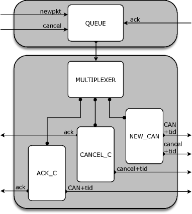
The protocol consists of processes: MULTIPLEXERH, NEW_CANH, CANCEL_CH, ACK_CH and QMSG.
-
•
The process MULTIPLEXERH is similar to FRAGH. It is the basic process that receives messages, and, depending on the type of the message, calls other processes. When there is no message handling going on, it idles until a new message arrives.
-
•
The process NEW_CANH handles a new CAN message received from a fragmentation protocol. In particular it stores the CAN message and determines whether the message is important enough to be forwarded straight to the CAN driver.
-
•
The process CANCEL_CH handles all actions to be performed when a cancellation message arrives from the fragmentation protocol.
-
•
The process ACK_CH reacts on incoming acknowledgements, stemming from the CAN driver. It forwards the acknowledgement to the fragmentation protocol to inform it that a new fragment could be sent; at the same time it sends another CAN message to the CAN driver, in case there is one in the local storage.
-
•
The last process concerns message handling. Whenever a message is received, it is first stored in a message queue. If the multiplexer is able to handle a message it pops the oldest message from the queue and handles it. This process ensures that the multiplexer is input enabled, as required in Sect. B.2.2.
B.5.1 Data Structure
The multiplexer has to store all incoming CAN messages, which were generated by instances of the fragmentation protocol. Since we assume that each CAN ID determines a unique sender, and that each application is sending only one message a time, it suffices to implement an array that maps CAN IDs to messages.
Our formal specification leaves the implementation details open and defines as a function. An implementation can be a function, an array, or a priority queue—it is the latter that has been implemented in our research vehicle.
The multiplexer also keeps track of the messages currently stored in the TX buffers. We assume a set of TX-buffer identifiers; the variables and range over . It is sufficient to store the (unique) CAN ID together with a flag that indicates whether the CAN controller is currently cancelling the message of the indicated TX buffer. To this end we define a function of type , where
For a function we define projections to access the first and second components.
The first function distils the CAN ID of a message that is currently stored in the TX buffer with identifier tid; the second one signals whether a cancellation message has been sent to the corresponding TX buffer. Moreover, we define a function that collects all CAN IDs that are currently stored in the TX buffers.
Finally we will use a partial function that determines the name of the TX buffer with the least urgent message (the one with the largest CAN ID):
When a TX buffer becomes available, we want to select a new message from the priority queue to send next—the one with the smallest CAN ID that is not already forwarded to the TX buffers:
where is defined to be the special element . By this latter definition becomes a total function; indicates that no message needs to be scheduled next.
To implement a proper prioritisation mechanism and to avoid the blocking example of Sect. 1 a multiplexer has to determine the CAN messages in the priority queue with highest priority (lowest CAN identifier)—these messages should be sent as soon as possible. Here corresponds to the number of available TX buffers.
In case there is only one TX buffer, as it is the case for the mission board, we can define a partial function similar to (Sect. B.2.1) that determines the identifier of the CAN message with highest priority currently stored in :
In case of TX buffers we require a function that determines messages. The easiest way is to define a recursive function. The base case () is a total function corresponding to the function :
Here, the second case describes the situation of an empty queue prio.
The recursive case () is then defined as
where for all and (in the case that is defined).
This recursive definition seems to be overly complicated. In fact when implementing a priority queue a simple position argument is enough to check whether a given CAN message msg is among the messages with highest priority: just insert msg into the queue and check if its position is smaller than . Since we want to abstract from implementation details, we chose, however, to present a recursive definition which allows different implementations.
In the specification presented below we have to determine whether a new message should be moved to a TX buffer immediately. Since the number of TX buffers is a constant, we define a function
As for the CAN receiver, we use a queue-style data structure for modelling an inbox queue. In particular we make again use of the standard functions , and .
The following table summarises the entire data structure we use for the multiplexer.
| Basic Type | Variables | Description |
| MSG | msg | messages |
| DATA | data | stored data |
| TX | tid, wid | identifiers of TX buffers |
| abort, suc | Boolean flags | |
| CID | cid, bid | CAN IDs |
| SID | CAN software component identifiers | |
| Complex Type | Variables | Description |
| msgs | message queues | |
| prio | priority queue for CAN messages | |
| txs | array of CAN IDs currently in TX buffer | |
| Constant/Predicate | Description | |
| special message symbol (indicating absence of a message) | ||
| special CAN ID symbol, denoting undefined CAN ID | ||
| empty queue | ||
| sending CAN driver identifier for hardware component | ||
| Function | Description | |
| cancellation message from fragmentation protocol | ||
| cancellation message to CAN driver | ||
| acknowledgement (from CAN driver and to fragm. prot.) | ||
| create CAN messages out of identifier and payload | ||
| wrapper function to add a TX-identifier to a message | ||
| selecting the most urgent CAN ID from priority queue | ||
| returns CAN IDs that should be scheduled | ||
| distils CAN ID of message in TX buffer | ||
| signals whether cancellation signal was sent to TX buffer | ||
| returns TX buffer with least urgent message | ||
| returns the ‘oldest’ element in the queue | ||
| removes the ‘oldest’ element in the queue | ||
| inserts a new element into the queue | ||
| gives name of fragmentation protocol handling a message | ||
B.5.2 Formal Specification
The Main Loop. The basic process MULTIPLEXERH (Process 9) receives messages from the fragmentation protocol or the CAN driver. Since the multiplexer is not always ready to receive messages, we equip the process with an in-queue (see below); so technically the multiplexer receives a message from this queue. MULTIPLEXERH maintains two data variables prio and txs. The former implements a priority queue which contains all CAN messages to be sent via the CAN bus; the later is a local storage which keeps track of the CAN IDs currently sent by or stored in the TX buffers of the CAN controller.
First, as usual, a message has to be received (Line 1). After that, the process MULTIPLEXERH checks the type of the message and calls a process that can handle this message: in case a CAN message is received from the fragmentation protocol, the process NEW_CANH is called (Line 4); in case of an incoming cancellation request the process CANCEL_CH is executed (Line 6); and in case a message from the CAN driver is read, the process ACK_CH is called (Line 8). In case a message of any other type is received, the process MULTIPLEXERH deadlocks; it is a proof obligation to check that this will not occur.
New CAN Message. In case a new CAN message is sent from an instance of the fragmentation protocol, the process NEW_CANH stores the CAN message and determines whether the newly received message is important enough to be forwarded directly to the CAN driver. The formal specification is shown in Process 10.
The received CAN message is first stored in the queue prio (Line 2), which contains all messages to be sent via the CAN bus. The protocol just stores the newly received message, it does not check for emptiness of . Therefore, to guarantee that no message is lost the property needs to hold before Line 2 is executed; it needs to be proven. The protocol then determines whether the message should directly be forwarded to the CAN driver—this is the case if the CAN ID is among the messages with lowest CAN IDs currently stored in prio (Line 4). Here equals the number of TX buffers available in the CAN controller. Lines 5–22 present all actions to be performed in case the message is forwarded to the CAN driver.
In case there exists an empty TX buffer , which is currently not used, the message should be sent to this TX buffer, and there is no need to erase a used TX buffer. The empty buffer is chosen in Line 6.252525Since is a free variable, it will be instantiated with a value that validates ; so the condition in the guard is satisfied iff . The CAN message is then forwarded to the connected CAN driver CH in Line 8. Since the CAN driver needs also the name of the TX buffer to be used, the value is sent next to the CAN message . The multiplexer also updates the local variable (Line 7), which keeps track of those CAN identifiers that are currently sent by or stored in the TX buffers. By this, the newly received message has been handled and the process can return to the main routine (Line 9).
In case all available TX buffers are used (Line 10), the least important message—the CAN message with the largest CAN ID—needs to be removed from the TX buffer and rescheduled later. This avoids the blocking example presented earlier. In Line 12 the process NEW_CANH determines the name of the TX buffer that contains the ‘worst’ message currently handled for sending. The CAN message that should be stored in this particular TX buffer cannot be put there immediately; a cancellation request needs to be sent first, and an acknowledgement needs to be received that informs the multiplexer about a free TX buffer. The routine checks whether a cancellation request was sent earlier, using the function . If this is the case, it returns straight to the process MULTIPLEXERH; otherwise a cancellation message is sent to the CAN driver CH, identifying the TX buffer that needs cancellation (Line 16).
If the newly received CAN message is not important enough to be forwarded to the CAN driver immediately (Line 23), the process NEW_CANH just returns to the main process (Line 24), where it awaits a new message. The stored message will be handled later when a TX buffer becomes available.
Cancellation Message. All actions to be taken if a cancellation request is received are formalised in Process 11. Any cancellation message received carries the CAN ID cid of the message to be cancelled.
In case the multiplexer has previously handled the message already, the value of is (Line 1). This situation can happen if for example the message was sent successfully, but the acknowledgement was not received by the time the fragmentation protocol requested the cancellation. In this case, the process has nothing to do, ignores the message and returns to the main process MULTIPLEXERH (Line 2).
In case the message that needs cancellation is still stored in the buffer the process first erases it from the buffer in Line 4. Afterwards it checks whether the CAN driver needs to be informed as well. This check is performed by analysing , which keeps the status of the TX buffers. In case there is a CAN message with identifier in TX buffer , the actions of Lines 8–13 are taken.
If the process CANCEL_CH has sent a cancellation request before, i.e., the flag is true, the process does not take any action, and returns to the main process (Line 9). Otherwise the flag is set to true (Line 11) and a cancellation message is sent to the CAN driver (Line 12).
If the message with CAN identifier can be found in prio but not in any of the TX buffers (in txs), no cancellation request needs to be forwarded and the cancellation process is finished (the message was not yet forwarded to the CAN driver). As a consequence the process informs the instance of the fragmentation protocol responsible for this message about the successful cancellation, by sending an ack-message in Line 16.
Notification from the CAN Driver. When an ack-message is received from the CAN driver by the multiplexer, the process ACK_CH is executed.
If the multiplexer received a message that carries an identifier of the TX buffer (), but has no local knowledge about it ( is undefined), something went wrong and the protocol deadlocks with an error. In the future we hope to show that this situation cannot occur.
Lines 3–22 present the standard case—an acknowledgement from tid is received, informing about the status of a message with CAN ID . Independent of the contents of the acknowledgement, the TX buffer is erased (Line 4). By this the array is adapted to the status of the actual TX buffers of the CAN driver—the message with ID cid was either sent successfully or erased from the buffer.
If the sending of the CAN message was successful (, Line 6), the message is erased from the priority queue (Line 7), and the corresponding instance of the fragmentation protocol (the one which is responsible for CAN ID cid, and determined by ) is informed about the success (Line 8). Since the TX buffer is now empty, the process checks whether there are pending messages that needs to be scheduled. If (Line 14) no message needs to be scheduled and the process returns to the main process MULTIPLEXERH, where it can receive new, incoming messages. In case there is at least one message stored in that is not yet forwarded to the CAN controller, the process chooses the message with best (least) CAN ID, using the function ; the least CAN ID is stored in the variable . This CAN message is then unicast to the controller, together with the name of the TX buffer to be used (Line 12); the local knowledge about is adapted in Line 11: the CAN ID is stored together with the flag true, indicating that no cancel request are sent for this message.
In case of a negative acknowledgement (), it matters whether the unsent CAN message (with identifier ) still occurs in the priority queue (). If this is the case (Line 17), the message must have been removed from the TX buffer in order to make place for a message with a higher priority. Since a TX buffer is now empty, a new CAN message can be passed to the CAN driver (if there is any). This scheduling happens in Lines 18–21, and is similar to Lines 10–13.
If the message that was dropped from the TX buffer does not occur in the priority queue (Line 6), the message must have been removed from the TX buffer in response to a cancellation request from the fragmentation protocol. The latter is informed about the successful cancellation in Line 8. Subsequently, the multiplexer schedules another message for transmission over the CAN bus if appropriate (Lines 9–16).
Message Queue. To guarantee that our system is non-blocking, the multiplexer is equipped with an in-queue. This input enabled queue (Process 13) runs in parallel with MULTIPLEXERH. Every incoming message from the fragmentation protocol or the CAN driver is first stored in this queue, and piped from there to the multiplexer MULTIPLEXERH, whenever MULTIPLEXERH is ready to handle a new message.
Here we simply assume that the length of the queue is unbounded. However, in the future we hope to show that under some mild conditions a queue with a limited capacity is equally effective.
The process is identical to the CAN receiver (Process 3 of Sect. B.2.2), except that the unicast-procedure is replaced by a send-action, which triggers the forwarding to the process MULTIPLEXERH.
The receive-action in Line 8 is needed to guarantee input-enabledness, meaning that the process QMSG is always ready to receive a new, incoming message, even when the process is about to send a message itself.
B.5.3 Initialisation
The multiplexer is initialised by , where for all cid, for all tid, and .