Concatenated LDPC-Polar Codes Decoding Through Belief Propagation
Abstract
Owing to their capacity-achieving performance and low encoding and decoding complexity, polar codes have drawn much research interests recently. Successive cancellation decoding (SCD) and belief propagation decoding (BPD) are two common approaches for decoding polar codes. SCD is sequential in nature while BPD can run in parallel. Thus BPD is more attractive for low latency applications. However BPD has some performance degradation at higher SNR when compared with SCD. Concatenating LDPC with Polar codes is one popular approach to enhance the performance of BPD , where a short LDPC code is used as an outer code and Polar code is used as an inner code. In this work we propose a new way to construct concatenated LDPC-Polar code, which not only outperforms conventional BPD and existing concatenated LDPC-Polar code but also shows a performance improvement of 0.5 dB at higher SNR regime when compared with SCD.
Index Terms:
Polar Codes; Belief Propagation Decoding (BPD); Low-Density Parity Check Codes (LDPC codes); successive cancellation decoding (SCD); Concatenated codes;I Introduction
Polar codes, since their invention by Arkan [1], have been proven to achieve the capacity for binary-input symmetric memory-less channels [1] as well as discrete and continuous memory-less channels [2]. Moreover, an explicit construction method for polar codes has been provided, and it is shown that they can be efficiently encoded and decoded with complexity , where is the code length. A number of decoding methods have been proposed for polar codes [3]-[7], and among these successive cancellation decoding (SCD) and belief propagation decoding (BPD) are the two most popular methods because of their performance and easy implementation in hardware.
Due to the serial nature of the algorithm, SCD suffers from longer latency. BPD, on the other hand, has the intrinsic advantage of parallel processing. Therefore, compared with SCD, BPD is more attractive for low-latency applications. In [6], a high throughput BPD (13.9Gbps) was proposed for (1024,512) polar codes which has an average decoding latency of 37.8 cycles with a maximum frequency of 515MHz. However despite its high throughput and lower latency, BPD suffers from performance degradation at higher SNR when compared with SCD [6, 7]. To improve the performance of BPD, several concatenated Polar codes with other block codes have been suggested in literature. Eslami et al. [8] proposed to concatenate polar codes and LDPC codes, both of long code lengths (), to be used in Optical Transport Network (OTN). This concatenated polar-LDPC code has been shown to outperform LDPC code of the same length at the cost of higher decoding complexity.
For smaller complexity overhead, Guo et al. [9] proposed to employ a short LDPC code as an outer code and larger Polar code as an inner code in the concatenated code. This concatenated LDPC-polar code results in 0.3dB improvement over standard BP decoding of polar code. On the similar note, for smaller complexity overhead, in this work we propose an alternate way to concatenate a short LDPC outer code with a larger inner polar code. Our proposed concatenated LDPC-polar code not only outperforms SCD and conventional BPD, but also achieves performance improvement of 0.25dB and 0.1dB, at higher SNR regime, when compared with existing concatenated LDPC-polar code [9] and list SCD decoder (list size = 2), [14] respectively.

II PRELIMINARIES
II-A Polar Codes and Belief Propagation Decoding
Polar codes are specified by a generator matrix , where is the code length and is the Kronecker power of . An polar code can be generated in two steps. First, an -bit message is constructed by assigning the reliable and unreliable positions as information bits and frozen bits, respectively. The frozen bits are forced to 0 and form the frozen set . Then, the -bit is multiplied with the generator matrix to generate an -bit transmitted code-word . Fig. 1(a) shows the encoding signal flow graph for polar codes, where the “” sign represents the XOR operation.
Due to the polarization phenomenon of polar codes, the bit channels () either become completely noiseless (termed as “good channels” for future reference) or completely noisy (termed as “bad channels” ). Bit channel qualities are measured by the corresponding Bhattacharyya parameter , where corresponds to Bhattacharyya parameter of the channel seen by the bit (suitably defined in [1]). Lower valuse of mean the corresponding bit channels have very small error probability, and hence they are known as good channels, and are used to carry information bits. On the other hand, higher values of imply that the corresponding bit channels have higher error probability, and thus they are bad channels, and are used for frozen bits.
Polar codes can be decoded by applying a BP algorithm over the corresponding factor graph [5]. Similar to the encoding signal flow graph, the factor graph for an polar code , is an -stage network which consists of nodes. Each node in the factor graph is associated with a right-to-left and a left-to-right likelihood message. and denote the right-to-left and left-to-right likelihood messages of the node at the stage and the iteration, respectively. Fig.1 (b) shows an example of a three-stage factor graph for polar codes. During the BP decoding procedure, these messages are propagated and updated among adjacent nodes using the min-sum updating rule [10], as shown in Fig.1 (c).
II-B Low-Density Parity Check Codes:
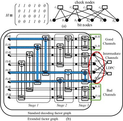
LDPC codes [12] are block codes characterized by a parity check matrix (), with a constraint on a codeword such that . The matrix of an example LDPC of code length 6 is shown in Fig 2 (a). LDPC codes are often represented in graphical form by Tanner graph, where rows of correspond to the check nodes and columns of correspond to the bit nodes, respectively. An edge connects a check node with a bit node , if and only if = 1. The number of edges () present in the tanner graph are equal to the number of 1’s present in the parity check matrix. For the example shown in Fig 2 (a), LDPC codes are usually decoded by applying iterative belief propagation algorithm on their tanner graph, where soft messages are propagated between the bit nodes and the check nodes in an iterative manner.
II-C Intermediate Channel LDPC Polar codes [9]:
Apart from the good or bad channels, there are a smaller number of bit channels which are not either completely noise free or completely noisy, hence they are called “Intermediate channels”. For a given polar code with information set intermediate channels correspond to those information bits which have relatively larger values of among all information bits. Guo et al. [9], proposed to apply a shorter outer LDPC code on these intermediate channels, to provide extra protection on these specific channels so that the overall performance of Polar codes can be improved. We call this approach as Intermediate Channel LDPC Polar codes (IC-LDPC Polar codes) for future reference.
Let denote the number of good channels and denote the number of channels on which outer LDPC code is applied (these channels are termed as for future reference), then the rate of polar code is calculated as: and the size of the information set is: The rate of overall concatenated LDPC-Polar code will be: , where is the rate of the outer LDPC code. Since both polar code and LDPC code can be decoded by belief propagation algorithm so the factor graph of a polar code can easily be extended to include the tanner graph of shorter LDPC codes for decoding as shown in Fig. 2 (b), where , , , and respectively.
III Proposed Concatenated LDPC-Polar code
We propose to use a different criterion to choose the set of bits to be protected by the outer LDPC code , based on the notion of smaller leafset size.
III-A Leafset Size for Information Bits [8]:
Eslami et al. [8], analyzed stopping trees as well as girth of polar codes and their effects on the performance of BPD. Every information bit in has a unique stopping tree rooted at that information bit (the right hand side of the factor graph) with its leaves at the code-bits (the left hand side of the graph). Fig. 2(b) shows a stopping tree rooted at an information bit as well as the corresponding leaf set ( ). Hence every information bit has an associated leaf set, and the number of code-bits in that leafset is called leafset size for that information bit. The leaf set size of the information bit , shown in Fig. 2(b), is 4. For two information bits with different leafset sizes, under belief propagation decoding, the one with smaller leafset size is more likely to be erased than the information bit with larger leafset [8].
III-B Proposed Criterion for Choosing Bits for Outer LDPC Codes
Due to the significance of the information bits with smaller leafset size, we propose to choose bits with smaller leafset sizes to be protected by outer LDPC code (). To simplify the calculation of leafset size for each information bit , we exploit the property that the leafset size of the information bit is equal to the weight of the row of generator matrix (Fig. 2(b)). Hence we will use leafset size and weight of information bit interchangeably, for the rest of the discussion. The pseudocode for choosing is presented in Algorithm 1.
For (1024,544) polar codes with and polar code rate can be calculated as , with . These 544 information bits contain bits with weight 16, 32, 64, 128, 256, 512 and 1024, hence the minimum weight for is 16. For choosing , these 544 information bits are divided into subsets such that contains all information bits with minimum weight 16, similarly contains all information bits with second minimum weight 32 and so on. The size of is 31 bits whereas the size of is 144. Then each of these subsets are sorted in descending order based on Bhattacharyya parameter( ). Thus the first bit in each subset has the highest value of and hence corresponds to the least reliable bit among all other bits in that subset . Finally first 64 bits are chosen from the set , such all 31 bits of are chosen and first 33 bits of , which are the least reliable bits of , are selected.
III-C Scheduling Scheme for Concatenated LDPC-Polar Code:
For the proposed concatenated LDPC-Polar code, round-trip scheduling [11] is employed. For the extended factor graph shown in Fig. 2 (b), one iteration in round-trip scheduling is completed when the information from the left side of the factor graph (i.e. the channel LLR) travels all the way to the right side of factor graph where it is passed as intrinsic (a priori) information to the the tanner graph of the LDPC, where bit nodes to check nodes messages are calculated and propagated toward the check nodes. Following this leftward information flow, check nodes to bits nodes message are calculated and passed to bit nodes. This extrinsic information from the tanner graph along with the frozen bit information of polar codes is propagated rightward towards the right side of factor graph and hence one iteration is completed.
III-D Complexity Analysis
In comparison with original BPD scheme, i.e., without LDPC concatenation (termed as baseline BPD), both IC-LDPC Polar codes and proposed LDPC-Polar codes have higher complexity due to the inclusion of tanner graph with the factor graph as shown in Fig. 2 (a). Complexity for the baseline BPD, for one iteration in the round-trip scheduling, is the summation of the complexity for leftward message propagation and the complexity for rightward message propagation and is equal to additions where is the length of polar code. For simplicity, one minimum operation is also counted as one addition. For (1024,512) polar code, the complexity of baseline BPD per iteration will be 40960 additions.
For the extended tanner graph, the complexity for one iteration will be the summation of the complexity of the baseline BPD and the complexity of the tanner graph. The complexity for the tanner graph can be calculated as the summation of the complexity for the bit nodes to check nodes message propagation and that for the check nodes to bit nodes message propagation. For a LDPC code with code bits and check bits, the complexity for bit nodes to check nodes message propagation is where, is the number of edges present in the tanner graph as mentioned in II-B. Similarly the complexity for check nodes to bit nodes message propagation is also . For (1024,544) polar code and a regular (3,6) LDPC code with code bits = 64 () and check bits = 32 (), the number of edges present in the tanner graph () is 192 and the complexity for one iteration in the round-trip scheduling is thus equal to 40960 + 384 + 384 = 41728 additions. Hence the concatenated LDPC-Polar code design incurs just a small complexity overhead of 1.84 % per iteration, over baseline BPD.
IV SIMULATION RESULTS
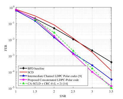
We carried out simulations on polar code of length 1024 and rate () 0.5 and compared the performance of the proposed concatenated LDPC-Polar code with the baseline BPD and the IC-LDPC Polar codes. Fig. 3 shows the simulation results over an AWGN channel with BPSK modulation. For all three BPD implementation, scaled min-sum approximation with scaling parameter ( α=0.9375 ) was used for the update equations Fig.1 (c). Similarly for all three BPDs, round-trip scheduling was employed and the maximum number of iteration are set to 60.
For both IC-LDPC Polar codes and proposed concatenated LDPC-Polar code, , and a regular LDPC code with and () is used as an outer LDPC code such that the overall concatenated LDPC-Polar rate () is and . Fig. 3 shows the simulation results. It can be seen that the proposed concatenated LDPC-Polar code results in 0.25dB and 0.5dB performance improvement at when compared with IC LPDC Polar code [9] and SCD respectively. Moreover, we have also compared with CRC-Aided Successive Cancellation List Decoder (CA-SCLD) with list size = 2 [14]. It is to be noted that, the overall code rate of CA-SCLD is 0.5 and it employs CRC-8 with . The proposed LDPC-Polar code has a performance improvement of 0.1dB at over CA-SCLD. Moreover with CA-SCLD CRC-8 takes a latency of 2660 cycles to decode one frame [14] whereas, due to highly parallel nature of BPD, the proposed LDPC-Polar codes will result in much lower latency.
V CONCLUSION
In this work, we have presented a novel concatenated LDPC-Polar code, where a small outer LDPC code is concatenated with a larger inner polar code. Information bit channels with smaller leafset size are proposed to be protected by outer LDPC code. The proposed concatenated LDPC-Polar code results in 0.5dB, 0.25dB and 0.1dB performance improvement at over SCD, an existing concatenated LDPC-Polar code approach and the state-of-the-art list decoder, respectively. Moreover the proposed concatenated LDPC-polar code only incurs a small complexity overhead of 1.84% per iteration, compared to baseline BPD. For future works, we intend to apply early stopping methods to further reduce the latency of decoding, hence to increase the throughput.
References
- [1] E. Arikan, “Channel polarization: A method for constructing capacity achieving codes for symmetric binary-input memory less channels,” IEEE Trans. Inf. Theory, vol. 55, no. 7, pp. 3051-3073, 2009.
- [2] E. Sasoglu, E. Telatar, and E. Arikan, “Polarization for arbitrary discrete memoryless channels,” in Proc. IEEE Inf. Theory Workshop (ITW), 2009, pp. 144–148.
- [3] A. Alamdar-Yazdi and F. R. Kschischang, “A simplified successive cancellation decoder for polar codes,” IEEE Commun. Lett., vol. 15, no. 12, pp. 1378–1380, Dec. 2011.
- [4] C. Leroux, I. Tal, A. Vardy, and W. J. Gross, “Hardware architectures for successive cancellation decoding of polar codes,” in Proc. IEEE Int. Conf. Acoust., Speech, Signal Process. (ICASSP), May 2011, pp. 1665–1668,.
- [5] E.Arıkan, “A performance comparison of polar codes and Reed-Muller codes,” IEEE Commun. Lett., vol. 12, no. 6, pp. 447–449, Jun. 2008.
- [6] S. M. Abbas, Y. Fan, J. Chen and C. Y. Tsui, "High-Throughput and Energy-Efficient Belief Propagation Polar Code Decoder," in IEEE Transactions on Very Large Scale Integration (VLSI) Systems, vol. 25, no. 3, pp. 1098-1111, March 2017.
- [7] J. Lin, C. Xiong and Z. Yan, "Reduced complexity belief propagation decoders for polar codes," in Proc. IEEE Workshop on Signal Processing Systems (SiPS), 1-6 October 2015.
- [8] A. Eslami and H. Pishro-Nik, "On finite-length performance of polar codes: Stopping sets, error floor, and concatenated design," in IEEE Transactions on Communications, vol. 61, no. 3,, March 2013, pp. 919-929.
- [9] J. Guo, M. Qin, A. Guill n i F bregas and P. H. Siegel, "Enhanced belief propagation decoding of polar codes through concatenation," in Proc. IEEE International Symposium on Information Theory 2014 , Honolulu, HI, 2014, pp. 2987-2991.
- [10] B. Yuan and K.K. Parhi, "Early stopping criteria for energy-efficient low-latency belief-propagation polar code decoders," IEEE Trans. Signal Process., vol.62, no.24, pp.6496–6506, Dec.15, 2014.
- [11] J. Xu, T. Che and G. Choi, "XJ-BP: Express journey belief propagation decoding for polar codes," in Proc. IEEE Global Communications Conference (GLOBECOM) 2015, San Diego, CA, 2015, pp. 1-6.
- [12] R. G. Gallager, Low Density Parity-Check Codes. MIT Press, Cambridge, MA, 1963.
- [13] Sarah J. Johnson and Steven R. Weller, Low-Density Parity-Check Codes: Design and Decoding, Wiley Encyclopedia of Telecommunications, 2003, pp.1-18.
- [14] A. Balatsoukas-Stimming, M. B. Parizi and A. Burg, "LLR-based successive cancellation list decoding ofpolar codes," IEEE Transactions on Signal Processing, vol. 63, no. 19, pp. 5165-5179, Oct.1, 2015.