Generation of single skyrmions by picosecond magnetic field pulses
Abstract
We numerically demonstrate an ultrafast method to create single skyrmions in a collinear ferromagnetic sample by applying a picosecond (effective) magnetic field pulse in the presence of Dzyaloshinskii-Moriya interaction. For small samples the applied magnetic field pulse could be either spatially uniform or nonuniform while for large samples a nonuniform and localized field is more effective. We examine the phase diagram of pulse width and amplitude for the nucleation. Our finding could ultimately be used to design future skyrmion-based devices.
Skyrmions, nanoscale swirling magnetic structures, are topological solitons that might be utilized as magnetic bits in the next generation of compact memory devices Polyakov ; Bogdanov_89 ; Bogdanov_94 ; Bogdanov_94_b ; Bogdanov_99 ; Bogdanov_06 ; Bogdanov_11 ; Kiselev_11 ; Fert2013 ; Nagaosa-2013 ; Romming_2015 ; Hagemeister ; Tomasello ; Zhang15 , thanks to their small size and intrinsic stability. It is believed that nanoscale static skyrmions with a definite chirality and a fixed topological number , suppmat are stabilized in the presence of a chiral Dzyaloshinskii-Moriya interaction (DMI), so-called DMI stablized skyrmions Bogdanov_89 ; Bogdanov_94 ; Bogdanov_94_b ; Bogdanov_99 ; Bogdanov_06 ; Bogdanov_11 while long-range dipole interactions stabilize bubble skyrmions Ezawa_10 ; Kiselev_2011 ; Klaui ; Finazzi with energetically degenerate chiralities and typically much larger diameters.
The possibility of a spontaneous skyrmion ground state in chiral magnets was first predicted by Rößler et al. Bogdanov_06 . The first observation of a skyrmion lattice, in the presence of a uniform magnetic field, was reported by Mühlbauer et al. in 2009 in the chiral magnet MnSi Muhlbauer2009 . Since then, skyrmion lattices have been observed in various noncentrosymmetric materials and ultrathin helimagnets through different experimental techniques Muhlbauer2009 ; Yu2010 ; Heinze ; Langner ; Mehlin ; Dussaux . Recently, the generation of skyrmion lattices at room temperature was also demonstrated woo ; Luchaire ; Tokunaga . Moreover a skyrmion lattice was observed in a Si-wafer-based multilayer system Schlenhoff , making promises for future technology more realistic.
However, for applications, generation of isolated skyrmions is obviously more interesting than a lattice, as individual skyrmions can be used as bits of information Xichao ; Zhou_rqce ; Fert2013 . In case of a single skyrmion, the creation methods are distinct from the ones for skyrmion lattices and so far, few have been demonstrated, either numerically or experimentally. It was numerically shown that charge currents, spin-polarized currents, local heating, and spin waves can create isolated skyrmions in chiral ferromagnetic systems Tchoe ; Lin ; sampaio ; iwasaki ; koshibae ; Liu_2015 ; Fujita . All numerical simulations so far have predicted skyrmion nucleation in nanoseconds, and e.g. in Ref. [Tchoe, ] a circulating current is essential whereas in Ref. [Lin, ] an unrealistic damping parameter larger than 0.1 is needed. Romming et al. observed the creation and annihilation of single skyrmions using a spin-polarized scanning tunneling microscope tip Romming13 , but to nucleate them an external magnetic field as well as very low temperature was needed. On the other hand, bubble skyrmions stabilized by dipole interactions were observed in a ferrimagnetic thin film of TbFeCo using ultrashort single optical laser pulses Finazzi , with a size of more than 100 nm. Creation of micron-sized synthetic skyrmions at room temperature has also been reported by current-induced spin-orbit torques (SOTs) skyrmionSOT .
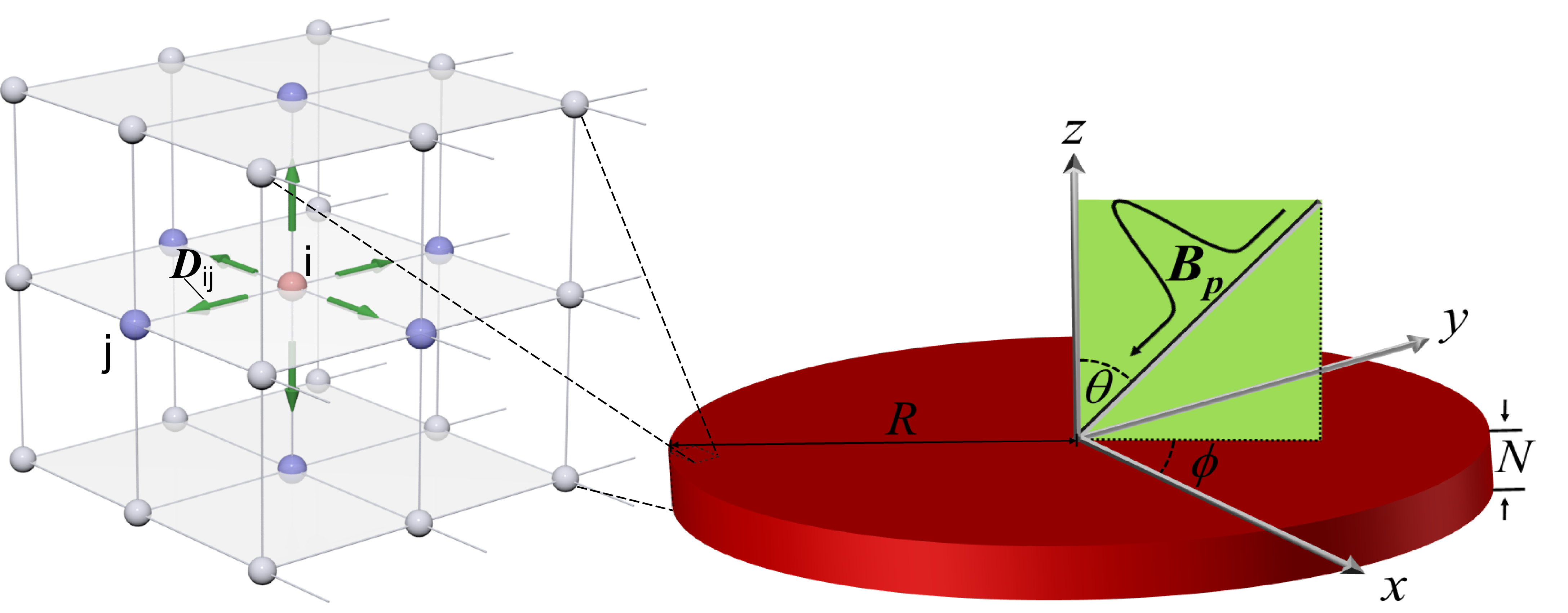
In this Rapid Communication, we propose an efficient method for the nucleation of a skyrmion at a subnanosecond time scale in a uniform ferromagnetic sample using picosecond Gaussian magnetic field pulses, see Fig. 1. Such fields can for example be created by applied laser pulses via the inverse Faraday effect IFE ; IFE-Alireza1 . For a large enough magnetic field pulse and for certain angles, spin waves are excited in the system and destabilize the ground state by exerting a magnonic SOT on the localized spins. Subsequently, an isolated skyrmion is dynamically nucleated in a metastable state in the presence of DMI. Successful nucleation of a skyrmion is observed, regardless of the sample geometry and size, using either spatially uniform or localized magnetic field pulses.
We use a classical model of localized magnetic spins. The total free energy of the system is given by,
| (1) |
where is the exchange interaction between neighboring local magnetic moments , and is the Heisenberg exchange constant. is the Dzyaloshinskii-Morya interaction where the DM vector for bulk DMI is defined as and for interfacial DMI is , with the strength of DMI, a unit vector pointing from site to site , and is the inversion symmetry breaking direction. is the anisotropy energy and is the out-of-plane uniaxial anisotropy constant. The coupling of an applied external magnetic field pulse , and the local spins is described by the Zeeman interaction . Here we assume , where is the Bohr magneton.
We consider a thin film of magnetic atoms with open boundary conditions and a simple cubic lattice structure with lattice constant , see Fig. 1. Our simulations show that, within the considered geometries, the effect of dipole interaction on the skyrmion nucleation is negligible, thus we ignore that. We assume a DMI strength less than the critical value , thus the ground state is collinear Stiles .
The spin dynamics is described by the Landau-Lifschitz-Gilbert equation Lazaro98 ,
| (2) |
where is the gyromagnetic ratio and is the Gilbert damping parameter. We have utilized a time dependent magnetic field pulse defined by a Gaussian function, applied in a direction . and are the amplitude and the Gaussian width of the pulse FWHM , respectively. can be either uniform through the whole sample or localized with a Gaussian profile inside the domain. To calculate the topological number, , on a discrete lattice we use the Berg and Lüscher formalism Berg81 ; suppmat .
We used an atomistic spin dynamics simulation method implemented in the juSpinX code David to study the temporal evolution of the magnetization. We also checked the results for larger samples, and investigated the effects of having a spatially localized and tilted magnetic field pulse by performing micromagnetic simulations using the simulation package MuMax3 mumax .
In our atomistic simulations we consider a nanodisc of (diameter thickness), and the time step is 1 fs. A typical simulation time is about 1 ns, which is long enough compared to a typical pulse width, , of the order of tens of ps. The magnetic field is spatially uniform and covers the entire sample. The used material parameters for atomistic spin dynamics are the exchange stiffness J = 5 meV/atom and dimensionless parameters K/J = 0.1, D/J=0.16 and = 0.05. In micromagnetic simulations we assumed a nanodisc of with a grid size of , with material parameters for CoPt and FeGe thin films, see Supplemental Material suppmat .
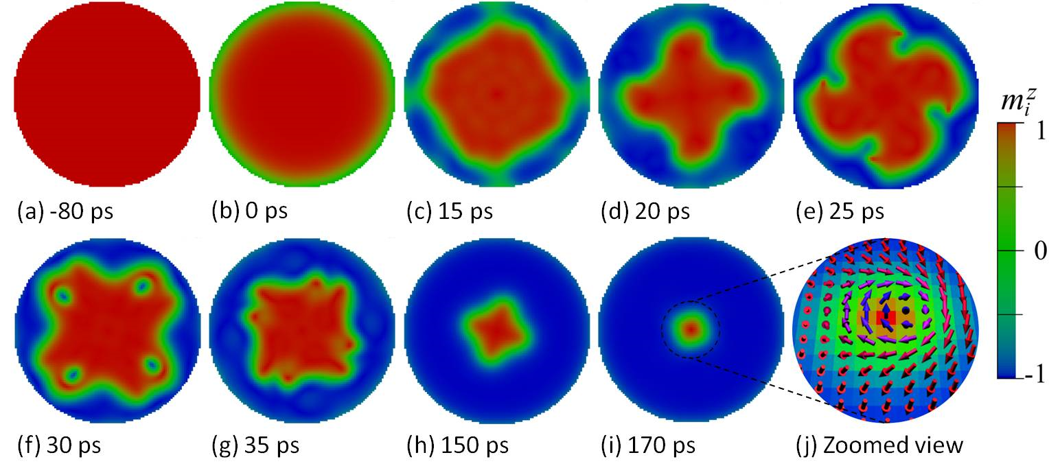
Figure 2 shows snapshot images of the temporal evolution of the magnetization in the nanodisc sample. The magnetic field pulse is applied at normal direction with an amplitude T and a pulse width ps. We found similar dynamics in a rectangular geometry in the atomistic simulation. Also the micromagnetic simulations for large nanodisc sizes and applying tilted magnetic fields show similar temporal evaluation, see Supplemental Material suppmat .
When the peak of the incident pulse arrives at , the sample becomes destabilized due to the excitation of spin waves and the subsequent magnonic SOT exerted on the local spins Manchon . While all localized spins are collinear within the sample, at the edges the combination of DMI and finite size effects causes a tilting of the spin directions. Applying a uniform and perpendicular magnetic field pulse then excites spin waves at the edges. For the nucleation of a skyrmion, the amplitude of the pulse must be large enough to destabilize the uniform ferromagnetic state. The pulse amplitude turns completely off at about 40 ps. As the final outcome, a chiral vortex-like skyrmion in the center becomes stabilized and the topological charge of the systems becomes Q01 . The time to nucleate a skyrmion in this way is of the order of 200 ps and is much faster than in other proposed methods using currents and current pulses iwasaki ; Lin . The formation of a domain with four fold symmetry in the center of the sample during the nucleation process, Figs. 2 (c)-(h), originates from the symmetry of the underlying lattice structure in the atomistic simulation, i.e. the square lattice, see also movie S1 in the Supplemental Material suppmat . In the micromagnetic simulations for different material parameters also a four-fold symmetry appears, see movie S2 in the Supplemental Material suppmat , but this is just an artifact of the finite difference discretization method.
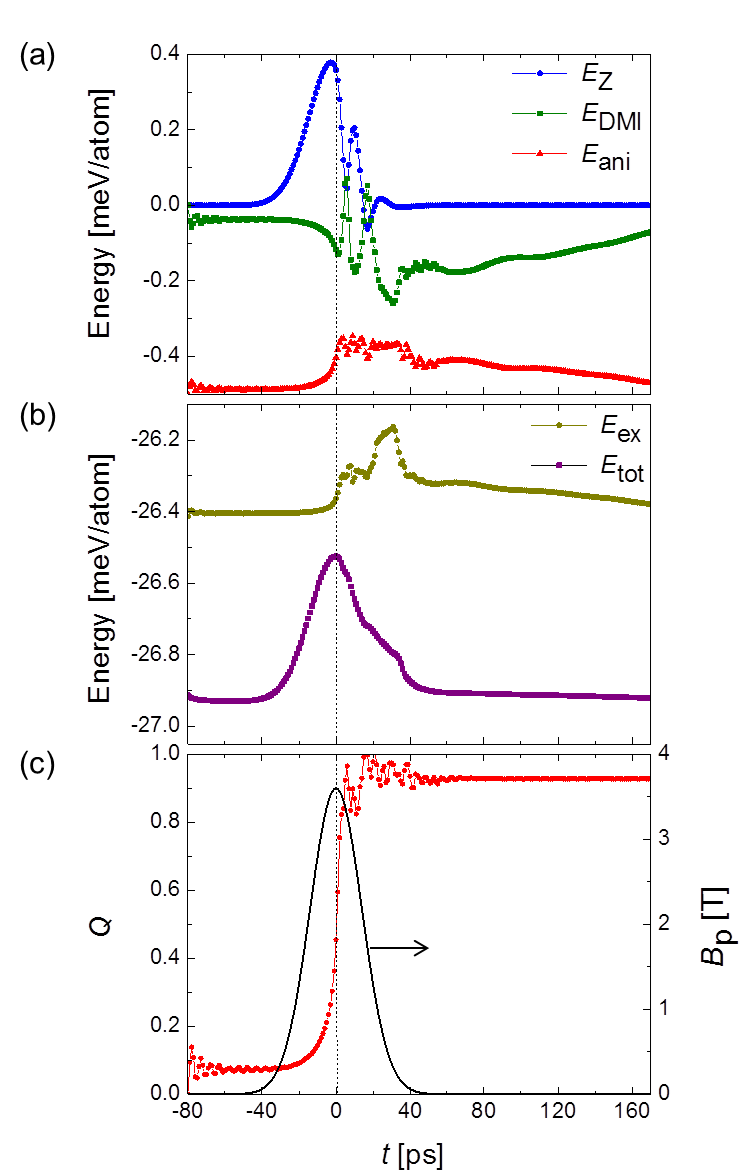
The total energy of the system , is the sum of the exchange energy , the DMI energy , the anisotropy energy , and the Zeeman energy , Eq. (1). Figures 3 (a and b) show the temporal evolution of each energy contribution resulting from the Gaussian magnetic field pulse . The separation into two figures is necessary due to the huge difference in energy scales between the exchange energy and the rest. Compared to the initial ferromagnetic state, the newly formed skyrmionic state is a metastable state Polyakov with slightly higher total energy, but the DMI energy becomes lower. The changing energies due to are accompanied by a changing and, when all energies are stabilized at about 40 ps, has eventually stabilized to one, Fig. 3(c).
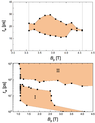
In Fig. 4 the phase diagrams of the nucleation of a skyrmion for both atomistic and micromagnetic simulations are shown. With the parameters chosen for the atomistic simulations the feasible area of skyrmion nucleation by applying a uniform and perpendicular magnetic field is given by a pulse strength from 3.3 T to 4.3 T and a pulse width from 10 ps to 30 ps for the circular shaped system, Fig. 4 a. This phase diagram is material parameter dependent and for optimized material parameters one can reduce the filed amplitude to just few hundreds of mT suppmat . To uncover whether this effect is only an edge effect, we did micromagnetic simulations for larger sample sizes in the presence of a localized and tilted applied magnetic field, with a temporal and spatial Gaussian profile. Skyrmion nucleation is even observed in larger samples by applying a spatially localized magnetic field pulse either far from or close to the sample edges. Because the ground state is collinear, to excite high enough spin wave amplitudes one needs to apply a tilted magnetic field pulse in such large systems. In Fig. 4b the phase diagram of skyrmion nucleation for a CoPt nanodisc of nm is plotted. The applied magnetic field is tilted , and localized at the center of the nanodisc with a spatial Gaussian width of nm. We checked the skyrmion nucleation for two different material parameters, CoPt and FeGe, thin films with larger sizes, see Supplemental Material suppmat . FeGe has bulk DMI while CoPt has interfacial DMI and consequently these two different symmetries lead to two different skyrmion structures, namely hedgehog (Néel type) skyrmions and chiral vortex-like (Bloch type) skyrmions, respectively. In both samples we found two nucleation regimes depending on the magnetic field duration. Short pulses create single skyrmions, indicated as regime I in Fig. 4b, while longer pulses generate multiple skyrmions, indicated as regime II. Between these two regimes there is a gap in the phase space at which we could not find any stable skyrmion nucleation. In larger systems, more stable skyrmions might be generated by longer magnetic field pulses. In small systems, while in the transient time regime, several skyrmion cores are created but because their distances are short, they repel each other and at the end, only one skyrmion is stabilized at the disk center.
These numerical results can be understood by the following minimal model. To overcome the barrier between a stable uniform ferromagnetic phase and a metastable skyrmionic phase, the ground state must be destabilized Lin ; Shibata . This is achieved by the creation of spin waves via the magnetic field pulse. Recently, it was shown that spin waves exert a torque on a uniform ferromagnet in the presence of DMI Manchon . Considering a uniform ferromagnetic state in which the DMI is smaller than a certain threshold, the magnonic SOT is given by Manchon ; Qaiumzadeh ,
| (3) |
where is the spin-wave current, and and are phenomenological constants related to the DMI strength. We consider spin waves with frequency and wavevector , as a deviation from a collinear state . The spin-wave energy reads,
| (4) |
Finding the magnetic field in which the imaginary part of the dispersion relation becomes zero, , and minimizing it with respect to the wavevector, we find a nonzero wavevector proportional to DMI strength, , that gives rise to a structural instability. In the absence of DMI the wavevector remains zero , which is equivalent to the initial uniform state. Finally the critical field to create such instability in the presence of DMI is given by,
| (5) |
Equation (5) gives the critical magnetic field required to generate spin waves with a finite wavevector. This minimum magnetic field does not create a uniform mode , as for ordinary spin-wave excitations, but rather a spin wave with finite wavevector () is excited by the magnetic field pulse. By applying a magnetic field , the initial uniform ground state, , is destabilized, and transferred to the metastable skyrmion state .
The skyrmionic state in our simulations could not be stabilized in the absence of DMI. This process occurs for a certain range of material parameters heo , e.g., the range of DMI, when , should be about in the atomistic trilayer circular sample. As the skyrmion diameter is proportional to , the skyrmion size is also limited. This range of DMI strength is experimentally accessible Romming_2015 ; Yang_2012 ; Nembach_2015 . Moreover, the damping value is also important to create a skyrmion. We used here , for both atomistic and micromagnetic simulations, which is a realistic value. For much higher damping than 0.05, the nucleation of a skyrmion cannot be stabilized due to the lack of sufficient spin wave propagation. This is in contrast with the current-induced single skyrmion case in which larger damping , is needed Lin . Finally, within the parameters chosen in the case of a uniform magnetic field normal to the sample, the typical range of the amplitude of a pulse is 3 T to 4 T, with about 20 ps pulse width to nucleate an isolated skyrmion in the center of the nanodisc. On the other hand, in the case of applying a localized and tilted magnetic field, the threshold field amplitude is reduced to 0.5 T while the temporal field duration can be much longer. In general a large enough external perturbation is needed to trigger the instability of the uniform initial state.
In summary, we showed that in the presence of either bulk or interfacial DMI and in a specific range of realistic material parameters, skyrmions can be generated by means of a magnetic field pulse of subnanosecond duration. Both spatially uniform and nonuniform localized pulses can create skyrmions in small and large samples. To achieve such magnetic field amplitudes and durations one can use the inverse Faraday effect arising from a circularly polarized laser pulse IFE ; IFE-Alireza1 , while fields of around a Tesla with pulse duration of 100 ps can be found in present day write heads write-head . This method is faster than other methods which have been proposed yet and might be even used for skyrmion nucleation in ferromagnetic insulators as well as conducting ferromagnets. Our results may boost the building of a next-generation of magnetic devices utilizing the skyrmion state. Recently, it was shown that by using the interlayer exchange coupling, skyrmions can be stabilized in a wider range of parameters Ashis . Thus we expect generation of skyrmions by using magnetic field pulse might be applicable to a large class of materials.
Acknowledgments
Authors thank N. S. Kiselev, R. A. Duine, B. Dupe, M. V. Mostovoy and A. N. Bogdanov for fruitful discussions. This work was supported by the European union seventh framework program FP7-NMP-2011-SMALL-281043 (FEMTOSPIN), ERC Grant agreement No. 339813 (EXCHANGE), and the Dutch science foundation NWO-FOM 13PR3118.
References
- (1) A. A. Belavin and A. M. Polyakov, Zh. Eksp. Teor. Fiz. PisMa Red. 22, 503 (1975); [JETP Lett. 22, 245 (1975)].
- (2) A. N. Bogdanov and D. A. Yablonskii, Sov. Phys. JETP. 68, 101 (1989).
- (3) A. Bogdanov and A. Hubert, J. Magn. Magn. Mater. 138, 255 (1994).
- (4) A. Bogdanov and A. Hubert, Phys. Status Solidi (b) 186, 527 (1994).
- (5) A. Bogdanov and A. Hubert, J. Magn. Magn. Mater. 195, 182 (1999).
- (6) U. K. Rößler, A. N. Bogdanov and C. Pleiderer, Nature (London) 442, 797 (2006).
- (7) U. K. Rößler, A. A. Leonov and A. N. Bogdanov, J. Phys. Conf. Ser. 303, 012105 (2011).
- (8) N. S. Kiselev, A. N. Bogdanov, R. Schäfer, and U. K. Rößler, J. Phys. D: Appl. Phys. 44, 392001 (2013).
- (9) A. Fert, V. Cros and J. Sampaio, Nat. Nanotechnol. 8, 152 (2013).
- (10) N. Nagaosa and Y. Tokura, Nat. Nanotechnol. 8, 899 (2013).
- (11) R. Tomasello, E. Martinez, R. Zivieri, L. Torres, M. Carpentieri, and G. Finocchio, Sci. Rep. 4, 6784 (2014).
- (12) J. Hagemeister, N. Romming, K. von Bergmann, E.Y. Vedmedenko, and R. Wiesendanger, Nat. Commun. 6, 8455 (2015).
- (13) X.C. Zhang, Y. Zhou, M. Ezawa, G. P. Zhao and W.S. Zhao, Sci. Rep. 5, 11369 (2015).
- (14) N. Romming, A. Kubetzka, C. Hanneken, K. von Bergmann, and R. Wiesendanger, Phys. Rev. Lett. 114, 177203 (2015).
- (15) See Supplemental Material at http://link.aps.org/supplemental/DOI for definition of on a discrete lattice, the phase diagram of skyrmion nucleation in FeGe thin films by applying a tilted magnetic field pulse as well as CoPt bilayers by applying a perpendicular magnetic field pulse.
- (16) M. Ezawa, Phys. Rev. Lett. 105, 197202 (2010).
- (17) N. S. Kiselev, A. N. Bogdanov, R. Schäfer, and U. K. Rößler, Phys. Rev. Lett. 107, 179701 (2011).
- (18) F. Büttner, C. Moutafis, M. Schneider, B. Krüger, C. M. Günther, J. Geilhufe, C. v. K. Schmising, J. Mohanty, B. Pfau, S. Schaffert, A. Bisig, M. Foerster, T. Schulz, C. A. F. Vaz, J. H. Franken, H. J. M. Swagten, M. Kläui, and S. Eisebitt, Nat. Phys. 11, 225 (2015).
- (19) M. Finazzi, M. Savoini, A. R. Khorsand, A. Tsukamoto, A. Itoh, L. Duò, A. Kirilyuk, Th. Rasing, and M. Ezawa, Phys. Rev. Lett. 110, 177205 (2013); T. Ogasawara, N. Iwata, Y. Murakami, H. Okamoto, and Y. Tokura, Appl. Phys. Lett. 94, 162507 (2009).
- (20) S. Mühlbauer, B. Binz, F. Jonietz, C. Pfleiderer, A. Rosch, A. Neubauer, R. Georgii, and P. Boni, Science 323, 915 (2009).
- (21) X. Z. Yu, Y. Onose, N. Kanazawa, J. H. Park, J. H. Han, Y. Matsui, N. Nagaosa, and Y. Tokura, Nature (London) 465, 901 (2010).
- (22) S. Heinze, K. von Bergmann, M. Menzel, J. Brede, A. Kubetzka, R. Wiesendanger, G. Bihlmayer and S. Blügel, Nat. Phys. 9, 713 (2011).
- (23) M. C. Langner, S. Roy, S. K. Mishra, J. C. T. Lee, X. W. Shi, M. A. Hossain, Y. D. Chuang, S. Seki, Y. Tokura, S. D. Kevan and R. W. Schoenlein, Phys. Rev. Lett. 112, 167202 (2014).
- (24) A. Mehlin, F. Xue, D. Liang, H. F. Du, M. J. Stolt, S. Jin, M. L. Tian, and M. Poggio, Nano Lett. 15, 7, 4839 (2015).
- (25) A. Dussaux, P. Schoenherr, K. Chang, N. Kanazawa, Y. Tokura, C. L. Degen and D. Meier, Nat. Commun. 7, 12430 (2016).
- (26) Y. Tokunaga, X. Z. Yu, J. S. White, H. M. Rønnow, D. Morikawa, Y. Taguchi, and Y. Tokura, Nat. Commun. 6, 7638 (2015).
- (27) S. Woo, K. Litzius, B. Krüger, M. Y. Im, L. Caretta, K. Richter, M. Mann, A. Krone, R. Reeve, M. Weigand, P. Agrawal, P. Fischer, M. Kläui and G. S. D. Beach, Nat. Mater. 15, 501 (2016).
- (28) C. Moreau-Luchaire, C. Moutafis, N. Reyren, J. Sampaio, N. Van Horne, C. A. F. Vaz, K. Bouzehouane, K. Garcia, C. Deranlot, P. Warnicke, P. Wohlhüter, J. M. George, J. Raabe, V. Cros and A. Fert, Nat. Nano. 11, 444 (2016).
- (29) A. Schlenhoff, P. Lindner, J. Friedlein, S. Krause, R. Wiesendanger, M. Weinl, M. Schreck and M. Albrecht, ACS Nano 9, 6, 5908 (2015).
- (30) X. Zhang, M. Ezawa and Y. Zhou, Sci. Rep. 5, 9400 (2015).
- (31) Y. Zhou and M. Ezawa, Nat. Commun. 5, 4652 (2014).
- (32) Y. Tchoe and J. H. Han, Phys. Rev. B 85, 174416 (2012).
- (33) S. -Z. Lin, C. Reichhardt and A. Saxena, Appl. Phys. Lett. 102, 222405 (2013).
- (34) J. Sampaio, V. Cros, S. Rohart, A. Thiaville and A. Fert, Nat. Nanotechnol. 8, 839 (2013).
- (35) J. Iwasaki, M. Mochizuki and N. Nagaosa, Nat. Nanotechnol. 8, 742 (2013).
- (36) W. Koshibae and N. Nagaosa, Nat. Commun. 5, 5148 (2014).
- (37) Y. Liu, G. Yin, J. Zang, J. Shi, and R. K. Lake, Appl. Phys. Lett. 107, 152411 (2015).
- (38) H. Fujita and M. Sato, Phys. Rev. B 95, 054421 (2017).
- (39) N. Romming, M. Menzel, C. Hanneken, J. E. Bickel, B. Wolter, K. von Bergmann, A. Kubetzka and R. Wiesendanger, Science 341, 636 (2013).
- (40) W. Jiang, P. Upadhyaya, W. Zhang, G. Yu, M. B. Jungfleisch, F. Y. Fradin, J. E. Pearson, Y. Tserkovnyak, K. L. Wang, O. Heinonen, S. G. E. te Velthuis, and A. Hoffmann, Science 349, 283 (2015).
- (41) A. Kirilyuk, A. V. Kimel, and Th. Rasing, Rev. Mod. Phys. 82, 2731 (2010); A. V. Kimel, A. Kirilyuk, P. A. Usachev, R. V. Pisarev, A. M. Balbashov, and Th. Rasing, Nature (London) 435, 655 (2005).
- (42) A. Qaiumzadeh, M. Titov, Phys. Rev. B 94, 014425 (2016); A. Qaiumzadeh, G. E. W. Bauer, and A. Brataas ibid. 88, 064416 (2013).
- (43) J.-H. Moon, S.-M. Seo, K.-J. Lee, K.-W. Kim, J. Ryu, H.-W. Lee, R. D. McMichael, and M. D. Stiles, Phys. Rev. B 88, 184404 (2013).
- (44) J. L. García-Palacios and F. J. Lázaro, Phys. Rev. B 58, 14937 (1998).
- (45) In experiments, however, the full width at half maximum (FWHM) of the peak is often used and is given by .
- (46) B. Berg and M. Lüscher, Nucl. Phys. B, 190, 412 (1981).
- (47) D. S. G. Bauer, P. Mavropoulos, S. Lounis and S. Blügel, J. Phys. Condens. Matter 23, 394204 (2011).
- (48) A. Vansteenkiste, J. Leliaert, M. Dvornik, M. Helsen, F. Garcia-Sanchez, and B. VanWaeyenberge, AIP Advances 4, 107133 (2014).
- (49) A. Manchon, P. B. Ndiaye, J. H. Moon, H. W. Lee and K. J. Lee, Phys. Rev. B 90, 224403 (2014).
- (50) Initial condition is a collinear state with . Having relaxed, the system obtains a finite small topological number thanks to the tilting of the spins at the boundaries. After applying a magnetic field pulse, a skyrmion is stabilized, but again because of the canted spins at the edges, the topological number of the system is less than unity.
- (51) J. Shibata, G. Tatara and H. Kohno, Phys. Rev. Lett. 94, 076601 (2005).
- (52) A.Qaiumzadeh, R. A. Duine, and M. Titov, Phys. Rev. B 92, 014402 (2015).
- (53) C. Heo, N. S. Kiselev, A. K. Nandy, S. Blügel, and Th. Rasing, Sci. Rep 6, 27146 (2016); B. Zhang, W. Wang, M. Beg, H. Fangohr, and W. Kuch, Appl. Phys. Lett. 106, 102401 (2015).
- (54) J. H. Yang, Z. L. Li, X. Z. Lu, M.-H. Whangbo, S.-H. Wei, X. G. Gong, and H. J. Xiang, Phys. Rev. Lett. 109, 107203 (2012).
- (55) H. T. Nembach, J. M. Shaw, M. Weiler, E. Jué, and T. J. Silva, Nat. Phys. 11, 825 (2015).
- (56) N. X. Sun, A. M. Crawford, and S. X. Wang, Mat. Res. Soc. Symp. Proc. 721, 249 (2002).
- (57) A. K. Nandy, N. S. Kiselev, and S. Blügel, Phys. Rev. Lett. 116, 177202 (2016).
See pages ,1,,2,,3, of SM.pdf