Interplay between Coulomb-focusing and non-dipole effects in strong-field ionization with elliptical polarization
Abstract
Strong-field ionization and rescattering beyond the long-wavelength limit of the dipole approximation is studied with elliptically polarized mid-IR pulses. We have measured the full three-dimensional photoelectron momentum distributions (3D PMDs) with velocity map imaging and tomographic reconstruction. The ellipticity-dependent 3D-PMD measurements revealed an unexpected sharp, thin line-shaped ridge structure in the polarization plane for low momentum photoelectrons. With classical trajectory Monte Carlo (CTMC) simulations and analytical methods we identified the associated ionization dynamics for this sharp ridge to be due to Coulomb focusing of slow recollisions of electrons with a momentum approaching zero. This ridge is another example of the many different ways how the Coulomb field of the parent ion influences the different parts of the momentum space of the ionized electron wave packet. Building on this new understanding of the PMD, we extend our studies on the role played by the magnetic field component of the laser beam when operating beyond the long-wavelength limit of the dipole approximation. In this regime, we find that the PMD exhibits an ellipticity-dependent asymmetry along the beam propagation direction: the peak of the projection of the PMD onto the beam propagation axis is shifted from negative to positive values with increasing ellipticity. This turnover occurs rapidly once the ellipticity exceeds 0.1. We identify the sharp, thin line-shaped ridge structure in the polarization plane as the origin of the ellipticity-dependent PMD asymmetry in the beam propagation direction. These results yield fundamental insights into strong-field ionization processes, and should increase the precision of the emerging applications relying on this technique, including time-resolved holography and molecular imaging.
pacs:
32.80.Rm,32.80.FbI Introduction
Recently, strong-field ionization in mid-infrared (mid-IR) laser fields has gained a lot of attention for the generation of coherent soft x-rays with high harmonic generation (HHG) Popmintchev et al. (2012) and for the discovery of a variety of strong field characteristica, like the observation of holographic electron interferences Huismans et al. (2011) and low-energy structures (Blaga et al., 2009; Quan et al., 2009; Wolter et al., 2015). These processes are typically described through the recollision of the electron wave packet with the residual ion (or parent ion). In a two-step model Sim , the electron is released to the continuum and subsequently driven back by the laser field towards the ion core where it can recollide. Upon return, the electron can either recombine, scatter inelastically or scatter elastically Pfeifer et al. (2006). Recombination of the electron with the ion leads to HHG McPherson et al. (1987); Ferray et al. (1988). Inelastic scattering leads to non-sequential double ionization Fittinghoff et al. (1992); Walker et al. (1994) and excitation of the ion Feuerstein et al. (2001).
However, the vast majority of the rescattering electrons undergoes elastic forward scattering, where the absolute value of momentum of the electron does not change on its trajectory past the parent ion. Interference of electrons with different ionization paths that end up with the same final momentum leads to many different structures, such as equidistant peaks in energy from above threshold ionization Agostini et al. (1979), electron-diffraction patterns Blaga et al. (2012), and holographic interference structures Huismans et al. (2011). Elastic rescattering can lead to signatures in photoelectron momentum distributions (PMDs) such as Coulomb-focusing Brabec et al. (1996); Comtois et al. (2005) and low energy structures Blaga et al. (2009); Quan et al. (2009); Wolter et al. (2015). These kind of signatures in PMDs have been assigned to forward scattering which is most pronounced at slow recollisions, i.e. recollisions where the momentum of the electron approaches zero at the time of recollision Sasaki et al. (2009); Liu and Hatsagortsyan (2010); Yan et al. (2010); Huang et al. (2010); Liu and Hatsagortsyan (2011); Kästner et al. (2012); Lemell et al. (2012); Möller et al. (2014); Kelvich et al. (2016).
Rescattering effects are the strongest with linear polarization of the laser pulse, however, rescattering is still observed with elliptical polarization, which is possible due to the spread of the returning wave packet Wang and Eberly (2009); Mauger et al. (2010); Liu and Hatsagortsyan (2012); Shafir et al. (2013); Li et al. (2014). The displacement amplitudes within the simple man’s model Sim , i.e. along the long axis and along the short axis of the polarization ellipse, depend linearly on the peak electric field and the inverse square of the laser frequency . Therefore, rescattering effects are expected to become more significant for mid-IR wavelengths even at moderate laser intensities. Moving from near-IR to mid-IR wavelengths will strongly increase the maximal kinetic energy which allows for diffraction experiments with increased resolution Pullen et al. (2015) and HHG with photon energies up to the order of 1 keV Popmintchev et al. (2012). Furthermore, discoveries like low energy structures Blaga et al. (2009); Quan et al. (2009); Wolter et al. (2015) and holographic interference patterns Huismans et al. (2011) were first observed at mid-IR wavelengths.
Another characteristic phenomenon of strong-field ionization at mid-IR wavelengths is the onset of non-dipole effects. When driven by mid-IR laser pulses, the magnetic field induced Lorentz force starts to become significant for the electron dynamics during the ionization process. The occurrence of magnetic field effects at long wavelengths has been theoretically predicted and described as the long-wavelength limit of the dipole approximation Keitel and Knight (1995); Walser et al. (2000); Milošević et al. (2000); Kylstra et al. (2001); Reiss (2008); Kohler et al. (2012). The Lorentz force along the laser propagation direction is responsible for the photon’s momentum transfer to electrons observed in Smeenk et al. (2009), and for the momentum partitioning between the ion and the electron during ionization Klaiber et al. (2013); Chelkowski et al. (2014); Cricchio et al. (2015); Chelkowski et al. (2015). The laser magnetic field induced drift is known to suppress the recollision and HHG at high laser intensities ( W/cm2 at a laser wavelength nm) Keitel and Knight (1995); Walser et al. (2000); Milošević et al. (2000); Kylstra et al. (2001); Dammasch et al. (2001); Klaiber et al. (2005); DiChiara et al. (2008); Ekanayake et al. (2013), at which the recolliding electron is deflected at the parent ion by more than the electron wave packet size Palaniyappan et al. (2006). At lower laser intensities the recollisions are still possible because Coulomb focusing can compensate the magnetic-field induced drift for linear polarization Førre et al. (2006).
Strong-field ionization experiments at mid-IR wavelengths revealed another phenomenon beyond the long wavelength limit of the dipole approximation Ludwig et al. (2014) which is relevant within this paper: an initially surprising shift of the peak of the projection of the PMD onto the beam propagation axis opposite to the beam propagation direction was observed. Also, the magnitude of this momentum shift was practically independent of the parent ion. The magnetic-field-induced lateral displacement of the electron and the successive recollision with the Coulomb potential was identified as the cause for this effect. This initial experiment triggered further experimental and theoretical investigations which is the focus of this paper.
Here, we therefore present a more detailed study of ellipticity-dependent strong-field ionization at mid-IR wavelengths taking into account non-dipole effects. We discuss two main results:
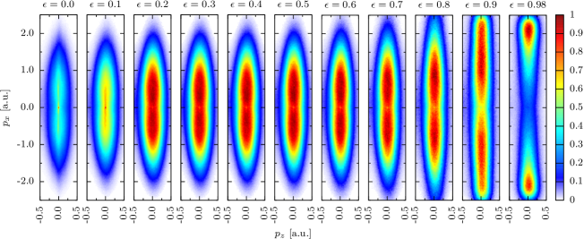
1) We observed the creation of a sharp, thin line-shaped ridge structure of low-momentum electrons in the polarization plane at small ellipticities (Fig. 1). Our analytical and numerical model show that this ridge structure stems mainly from Coulomb-focused electrons undergoing multiple revisits of the parent ion with at least one significant rescattering event.
2) We investigated how non-dipole signatures on the PMDs depend on laser ellipticity. The shift of the peak of PMDs with respect to the beam propagation axis (Fig. 2)is opposite to the beam propagation direction for both linear polarization and small ellipticites, and is directly related to the sharp, thin line-shaped ridge structure created by Coulomb-focusing in the 3D PMDs. With increasing ellipticity we then observe a shift of the PMD peak into beam propagation direction (Fig.2 (b)) which gives a direct link between the results observed in Ref. Ludwig et al. (2014) and the radiation pressure picture in Ref. Smeenk et al. (2011) that was employed to explain a shift in beam propagation direction.
The relationship between Coulomb focusing and non-dipole effects explored here increases our understanding of electron ionization dynamics in mid-IR laser fields, helps to better understand initially unexpected features of the observed PMDs, and will allow us to further exploit these effects to significantly enhance the resolution of the attoclock, time-resolved holography and strong-field molecular imaging using mid-IR lasers.
The paper is organized as follows: In section II, we present the details of the experiment; in section III we present 3D PMDs recorded with elliptical polarization. We compare the experimental results with classical trajectory Monte-Carlo (CTMC)-simulations; In section IV.1 and IV.2 we present theoretical models to explain the creation of ridge caused by Coulomb-focused electrons. The results of the ellipticity-dependent non-dipole effects on the PMD are presented in section V.
II Experimental Details
PMDs were recorded with a velocity map imaging spectrometer (VMIS) Eppink and Parker (1997); Parker and Eppink (1997) with the gas nozzle integrated into the repeller to achieve high gas target densities in the interaction region Ghafur et al. (2009); Weger et al. (2013). The target was ionized by an optical parametric chirped-pulse amplifier (OPCPA) system based on chirped quasi-phase-matching devices. This system can deliver pulses with duration of 44 fs and a pulse energy of 22 J at a center wavelength of 3.4 m and a high repetition rate of 50 kHz Mayer et al. (2013, 2014). The pulses were focused with a backfocusing dielectric mirror with a focal length of 15 mm into the interaction region. The polarization of the laser beam was controlled by two custom-made achromatic MgF2 wave plates. A quarter-wave plate induces the ellipticity and the subsequent half-wave plate controls the orientation of the polarization ellipse. The wave plates were fully characterized via polarimetry measurements where the power transmitted through a polarizer was recorded as a function of the angle between the major polarization axis and the polarizer axis. The polarization state at the desired orientation was extracted via a fit and interpolation of the measured values.
The intensity in all experiments was calibrated with reference measurements at close-to-circular polarization. The radial maximum of the torus-shaped momentum distribution was compared with semiclassical Monte-Carlo simulations Pfeiffer et al. (2012).
Throughout the article, the following coordinate system will be used: The coordinate denotes the direction of beam propagation, the major and the minor axis of the polarization ellipse and the respective electron momenta. denotes the PMD, i.e. the amplitude of the photoelectron signal.
The experiments require an accurate determination of the zero momentum spot, in particular on the beam propagation axis. This spot was identified via a sharp point in the center of the PMD recorded with linear polarization that stems from the ionization of atoms that were left in a Rydberg state by the laser pulse and were subsequently ionized by the static electric field of the spectrometer Nubbemeyer et al. (2008); Smeenk et al. (2011). As these electrons do not interact with the pulse, they are guided by the static electric spectrometer field to the position on the detector that corresponds to zero momentum in the ()-plane. The exact position of zero momentum in -direction was determined from the projection of a small range of 0.05 a.u. in of the PMD onto the -axis. This projection was fitted with a Lorentzian profile. This method was also applied to find the center in -direction. Throughout the article, atomic units (a.u.) are used.
III Three Dimensional Photoelectron Momentum Distributions (3D PMDs)
We recorded 3D PMDs at various ellipticities at an intensity of W/cm2 to study the ellipticity-dependence of rescattering in mid-IR laser pulses. When the ellipticity is varied, the electron dynamics changes mainly in the polarization plane, i.e. the -plane. To have access to the polarization plane, we record full 3D PMDs from strong-field ionization. The full 3D PMD is obtained by applying a tomographic reconstruction algorithm to the projected PMDs measured with velocity map imaging Wollenhaupt et al. (2009); Smeenk et al. (2009); Dimitrovski et al. (2014). The orientation of the 3D PMD with respect to the detector plane is linked to the orientation of the polarization ellipse, allowing us to rotate the PMD by rotating the polarization ellipse. The beam propagation axis is parallel to the detector plane. The polarization is rotated in steps of two degrees and a photoelectron image is recorded for each angular step. Subsequently, for each slice along the beam propagation direction, a filtered back-projection algorithm is applied for the tomographic reconstruction.
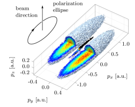
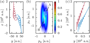
An example of a measured 3D PMD is visualized as an isosurface in Fig. 1. The isosurface exhibits two main lobes and a sharp ridge around .
In the following we distinguish between two types of photoelectrons:
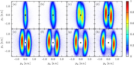
Type A photoelectrons: The ellipticity dependence of the PMDs in the polarization plane is shown in Fig. 3. Cuts of the 3D PMDs through the polarization plane (i.e. ) are shown in Fig. 3 for ellipticities of 0.03, 0.07, 0.11, 0.15, 0.19, 0.23, 0.26. For the cuts we integrated over a range of a.u.. The cuts show that, with increasing ellipticity, the cigar-shaped PMD evolves into a torus-like shape that is characteristic for strong field experiments with elliptically polarized pulses, such as typically observed with attoclock experiments Eckle et al. (2008a, b). The appearance of the two maxima on the short axis of the polarization ellipse can be explained by a simple man’s model Sim . Throughout this article, we will refer to the electrons ending in these maxima as type A electrons, as indicated in Fig. 5. Within the framework of this model, the maxima are shifted by 90∘ with respect to the phase at which the maximum of the electric field occurs. Deviations from 90∘ that are expected from the simple man’s model are due to the Coulomb-interaction of the electron with the ion core Bashkansky et al. (1988); Eckle et al. (2008b); Pfeiffer et al. (2012), ionization delay times Eckle et al. (2008a, b); Landsman et al. (2014) and multi-electron effects like the induced dipole moment due to the ion’s polarizability Pfeiffer et al. (2012).
Type B photoelectrons: In the evolution of the PMDs, one can observe for small elliptictities, in particular for and , the appearance of a sharp, thin line-shaped ridge structure around . To the best of our knowledge, no such sharp separated structure has been observed in near-IR-experiments conducted at wavelengths around 800 nm. For the rest of this article, we will refer to these electrons as type B electrons.
To understand the nature of type B electrons, we compare them with CTMC simulations using the two-step model of strong-field ionization. The initial conditions for the photoelectrons (ionization times, positions and momenta) are obtained from tunnel ionization theory in parabolic coordinates Perelomov and Popov (1967); Ammosov et al. (1986); Delone and Krainov (1991); Tun ; Pfeiffer et al. (2012), while the trajectories of the electrons are obtained by solving Newton’s classical equations of motion in the electromagnetic field of the laser pulse and the Coulomb potential of the parent ion. Subsequently the trajectories are binned in momentum space. We first compare the outcome of the simulations with our experiments in the polarization plane. The results are shown in Fig. 4. The semiclassical simulations were able to reproduce the appearance of the type B photoelectron signal. Our semiclassical approach does not take into account the quantum interference of the electron trajectories in the continuum, and thus we can conclude that the appearance of this structure is due to momentum space focusing of photoelectrons and is not created by a pure interference effect.
In order to understand if the creation of the ridge of type B electrons was induced by magnetic field effects, that appear at our beam parameters Ludwig et al. (2014), we performed the CTMC-calcuations with and without the inclusion of the magnetic field component (Fig. 4 (b) and (d)). The CTMC calculations reproduce the sharp structure of type B-electrons in the plane equally well. Thus, we conclude that for the appearance of type-B electrons in the polarization plane the magnetic field is not essential. Furthermore, to confirm that the structure was created under the influence of the Coulomb-potential of the ion, we performed CTMC-simulations with and without the Coulomb-potential included. It is obvious from the comparison of Figs. 4 (c) (Coulomb-potential not included in simulation) and (d) (Coulomb-potential included) that the inclusion of the Coulomb potential is required to reproduce the experimental data.
Type A and type B electrons have different characteristic position-space trajectories as shown in Fig. 5. Type A electrons travel directly to the detector without revisiting and do not have a point of intersection in the plane. However, type B electron trajectories have a point of intersection in the plane and furthermore, they cross multiple times.
IV Coulomb focusing at elliptical polarization
IV.1 Creation of the sharp, thin line-shaped ridge structure in the 3D PMD
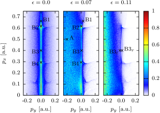
To understand the nature of this ridge structure in more detail, we analyze the 3D PMD in the polarization plane (i.e. in the -plane). We begin the analysis in the simpler case of a linearly polarized laser field and transfer the results to the case of elliptical polarization with . Fig. 6 shows the results of CTMC simulations in dipole approximation for three different ellipticities: , and . To focus on the mechanism of the creation of the ridge, we consider only electrons starting in the central half-cycle of the laser field to suppress the influence of ionization from multiple half cycles. Furthermore, we neglect the magnetic field effects to disentangle the creation of the ridge in the -plane from additional effects in beam propagation -direction.
As we saw in section III, the ridge already appears within the dipole approximation because the CTMC simulated PMD in the polarization plane did not depend on the magnetic field. In the case of linear polarization, the features of the PMD are understood in the terms of laser-driven classical trajectories recolliding with the parent ion. Due to the nature of the Coulomb interaction, a bunching of electrons occurs and is imprinted on the PMD in the form of caustics (Fig. 6). There are two kinds of caustics: horizontal and vertical. Each horizontal caustic line in the PMD corresponds to a certain class of rescattered trajectories. When the longitudinal momentum of the electron at the recollision is vanishing, i.e. the slow recollision condition is fullfilled, longitudinal bunching of electrons occurs Kästner et al. (2012). This condition depends on the ionization phase (i.e. the phase of the laser electric field when the electron appears in the continuum).
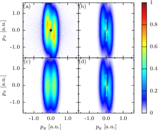
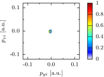
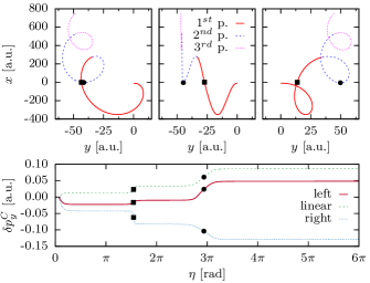
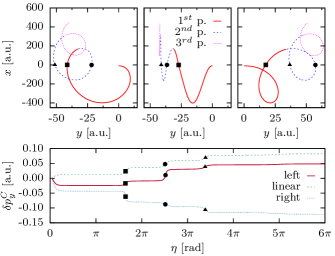
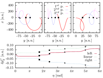
In Fig. 5, we indicate several characteristic points exhibiting qualitatively different rescattering behavior. Point A is an example of a type A electron, while points indicate type B electrons with n rescattering events. For these cases the sharp peak in the distribution around , can be seen due to Coulomb focusing. This peak is pronounced for small ellipticities, but starts to disappear for .
In order to understand this vertical ridge further, we analyze the set of initial transverse momentum distributions (i.e. at the tunnel exit) corresponding to the final transverse momentum values given by points . The resulting distributions are shown in Fig. 7. We analyze the initial transverse momentum distribution at the tunnel exit with momentum bins of a.u. placed at characteristic points of the PMD. We compare the initial PMDs of corresponding points for linear and elliptical polarization (Fig. 7).
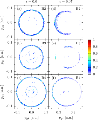
The ridge originates from a contraction in momentum transverse to the major polarization axis. In a linearly polarized laser field, the electrons contributing to the ridge are ionized with a nonvanishing transverse momentum at the tunnel exit, and appear after propagation with a vanishing transverse momentum. Their initial distribution is a ring in the ()-initial momentum distribution, see Fig. 7, left column. in the case of a linearly polarized laser field, the electrons which are initially (i.e. at the tunnel exit) distributed inside this ring obtain a large momentum transfer during recollisions and end up outside of the chosen final momentum bin near the vanishing transverse momentum.
In the case of the elliptically polarized laser field, there are two modifications to this picture. For small ellipticities (quantified in Eq. (9) below) the rescattering and Coulomb focusing, similar to the case of linear polarization, takes place for electrons which initially are distributed in a shifted ring of initial momenta in the ()-plane. The size of the shift is discussed further in section IV.2). The radius of the ring of the initial momentum space distribution is an indicator for Coulomb focusing. It is nearly the same for linear and elliptical polarization, i.e., Coulomb focusing for these trajectories is qualitatively the same. The points B2 and B4 in Fig. 6 corresponding to the slow recollision condition do not change their position in the PMD when changing ellipticity, which is due to the similarity of the underlying trajectories.
Next, we analyze these trajectories analytically to show that the Coulomb focusing dynamics is similar for linear and elliptical polarization up to a certain value of ellipticity (especially in the case of slow recollisions). Furthermore, we show that the recolliding electrons, which create the ridge, end up around .
The underlying electron trajectories are obtained from the solution of the electron equations of motion in an elliptically polarized laser field assuming that the Coulomb field effect is a perturbation, which affects the electron trajectory near the tunnel exit and at recollisions. The electric field component of the laser field is
| (1) | |||||
| (2) |
with the phase , the ellipticity , the field amplitude , and the intensity . The envelope of the pulse is neglected. For the electron dynamics in the laser polarization plane after the ionization, taking into account initial Coulomb momentum transfer at the tunnel exit, we have:
| (3) | |||||
| (4) |
where is the ionization phase, is the initial transverse electron momentum, and and are initial Coulomb momentum transfer. The electron rescattering and Coulomb focusing in an elliptically polarized laser field will be similar to the case of linear polarization, when the Coulomb momentum transfer during recollision is the same in both cases: . For the latter it is necessary to have the same impact parameter of the recollision, i.e. the same recollision -coordinate. This condition is fulfilled when the initial momentum at the tunnel exit is shifted with respect to the linear polarization case by a value to compensate the momentum imparted to the electron by the -component of the laser field (as well as a small difference of the initial Coulomb momentum transfers). The value of this shift at the slow recollision condition is:
| (5) |
see the derivation in the appendix A. Here, the superscripts and refer to the cases of elliptical and linear polarization, respectively. The final momentum of the type B electron is found by combining Eqs. (4) and (5):
| (6) |
where we have taken into account that and , i.e. that in the case of linear polarization the main ridge due to Coulomb focusing is at . The final momentum of the type B electron has practically a vanishing value. In fact, Shvetsov-Shilovski et al. (2009), and at the first slow recollision, and , at , where is the phase of recollision. All numerical estimations in this section are for ( nm), (intensity W/cm2). Thus, neglecting initial Coulomb momentum transfer for simplicity, we can conclude that in the case of elliptical polarization, the electrons with slow recollision condition are initially distributed in momentum space () on the ring centered at
| (7) |
with a radius and finally will end up at the ridge around . This is illustrated in Fig. 7, right column, where the top (B2) and bottom (B4) panels correspond to the slow recollision condition. The radii of the rings in B2 and B4, which indicate the magnitude of Coulomb focusing, do not change significantly due to the change in ellipticity. Thus, we can conclude that Coulomb focusing dynamics is very similar in both cases.
At non-negligible ellipticities the electrons around vanishing initial transverse momentum experience no recollision, no momentum change due to the Coulomb field besides the initial Coulomb momentum transfer when the electron leaves the tunnel exit. They contribute to the lobes of the final -distribution, with the final momentum , with the initial Coulomb momentum transfer . The latter is mostly along the electric field for the experimental parameters (the transverse component of initial Coulomb momentum transfer is smaller with respect to the longitudinal component by an order of magnitude), i.e., perpendicular to the vector potential, and induces a distortion of the PMD ellipse with respect to the case of the simple man’s model []. The initial momentum space corresponding to the center of the main lobe A is shown in Fig. 8 and indicates the absence of Coulomb focusing (the initial and the final phase space are the same).
Next we want to estimate up to which ellipticities the central sharp ridge of Coulomb focusing electrons still appears in the PMD. The discussion above is valid if the required initial transverse momentum of type B electrons according to Eq. (5), , is within the momentum width tunnelled electron wave packet. The latter reads
| (8) |
where is the PMD width ( of the Gaussian distribution) at the tunnel exit according to tunnel-ionization theoryPerelomov and Popov (1967); Ammosov et al. (1986) With Eq. (8) we conclude that the ridge in the PMD can exist up to ellipticities
| (9) |
There are also modifications of the rings in Fig. 7, especially for B3, which we discuss later in the next section based on trajectory analysis of these characteristic points. Note that the inner rings in the linear case in Fig. 7 are caused by trajectories with multiple significant rescattering events. However, such trajectories are strongly suppressed for increasing ellipticity.
Finally, let us estimate at which ellipticity the side lobes will be separated from the sharp ridge in the PMD. The side lobes appear when the ellipticity is large enough such that the Coulomb momentum transfer at recollision, for the electron with initial , is negligible with respect to the final momentum. The final electron momentum can be estimated as
| (10) |
and the Coulomb momentum transfer as
| (11) |
where , , , are the electron coordinates, and the distance from the core at the recollision point, respectively. is the recollision duration: . For the latter, we assumed that during the recollision time the electron travels a distance of the order of in x-direction , i.e., when we apply the condition for slow recollision. Estimating the recollision coordinate as , we have for the Coulomb momentum transfer . Thus, Coulomb focusing at recollision will be negligible, , if the ellipticity is relatively large
| (12) |
At ellipticities larger than this value, the lobes in the -plane begin to appear.
IV.2 The structure of the sharp, thin line-shaped ridge in the 3D PMD
To investigate the structure of the sharp ridge, (Fig. 1), we analyse in this section the corresponding trajectories. The structure of the ridge is very similar to the linear polarization case at the slow recollision condition. The structure slightly deviates from the linear polarization case outside of the slow recollision condition.
In Fig. 9, we analyze typical trajectories corresponding to each of the points B2, B3, B4, and originating from the left and right parts of the ring of initial momentum distribution (Fig. 7). We choose left and right points which have the same final vanishing momentum,
| (13) |
The difference of the initial momenta of these points determines the diameter of the ring of the initial momentum distribution of Fig. 7, which depends on Coulomb momentum transfer during recollision, and is an indicator of Coulomb focusing:
| (14) |
see the derivations for this section in Appendix B. The center of the ring is given by
| (15) |
which includes initial Coulomb momentum transfer and Coulomb momentum transfer during recollision correction into Eq. (7), and indicates that in the case of elliptical polarization the ring of the initial momentum distribution for the sharp ridge electrons is shifted due to the drift momentum along the minor axis of polarization, and by initial Coulomb momentum transfer in that direction as :
| (16) |
where describes the shift of the initial momentum along the -axis at an ellipticity compared to the linear case. For an ellipticity of , we have .
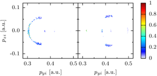
The diameter () of the ring in the initial momentum distribution, the indicator of Coulomb focusing, depends on Coulomb momentum transfer during recollision, but not on initial Coulomb momentum transfer (see appendix B, Eq. (34)). For all three points B2, B3, B4, the Coulomb momentum transfer during recollision is approximately the same as in the case of linear polarization, cf. Fig. 9. Therefore, the radius of the ring in the initial transverse momentum distribution and the ridge in the final PMD are also approximately the same.
We next analyze the modifications of the ridge with the variation of ellipticity. For the points B2 and B4 and linear polarization the main Coulomb momentum transfer during recollision takes place at the slow recollision, . This corresponds to the second recollision for B2, and the fourth one near B4, although there are multiple recollision points, , two at B2, and four at B4 (see Fig. 9). In the elliptical polarization case, the Coulomb focusing for the trajectory coming from the left part of the ring resembles the linear case, since the slow recollision has the same impact parameter and the same Coulomb momentum transfer during recollision. Of the multiple recollisions that occur for these points, the slow one has the dominant effect on the final momentum. Therefore, the Coulomb focusing for the left half-ring in Fig. 7 is the same for both linear and elliptical polarizations, thereby creating the central ridge in the PMD in both cases.
In contrast, the trajectory from right part of the ring at B2 in the elliptical polarization case differs from the linear one, see Fig. 9, upper panel. The first rescattering for this trajectory, additional to the slow recollision, takes place with shorter impact parameter than in the linear case due to the oscillating part of the -coordinate, yielding to the increase of the total Coulomb momentum transfer. This explains the larger radius of the right half-cycle of the ring structure at B2 in Fig. 7. The right-type trajectories are more sensitive to the initial conditions and, consequently, the ring width is significantly smaller. Moreover, the ionization probability is smaller for the right part of the ring because of the lager initial momenta. These explain why the central ridge becomes less pronounced with increasing ellipticity.
However, the right trajectories for B4, and trajectories ending up on the central ridge at smaller than for B4, start to resemble the linear case again. This is because for the ionization phases that are relevant to the latter trajectories, the oscillating part of the -coordinate does not perturb the recollision coordinates significantly. The condition that the recollision coordinate is only weakly perturbed by the ellipticity, i.e. , leads to an estimate of the threshold ionization phase (see appendix C):
| (17) |
for . The numerical value in the equation above is estimated for the parameters of Fig. 6, i.e., at , which assumes , the recollisions and Coulomb focusing in the elliptical polarization case will be similar to the linear one. This estimation fits to the CTMC calculation in Fig. 6.
The ring of the initial momenta of point B3 is deformed in a stronger way then the one for B2. The deformation is due to the fact that both left and right trajectories are perturbed with respect to the linear polarization case because of the quiver motion in the transversal -direction. The perturbed trajectories are more sensitive to the initial conditions, which results in a variable width of the ring in the initial momentum distribution. Moreover, the recollision coordinates for both left and right trajectories are different. Therefore, the Coulomb momentum transfer during recollision for the left and right trajectories are not symmetric which leads to the bend of the central ridge. Furthermore, at larger ellipticities, e.g. , the central ridge at B3 is split, when the left- and right-side trajectories yield to different ridges, see Fig. 10. However, this splitting is not visible in the experimental data due to focal volume averaging, CEP averaging and the laser pulse shape.
V Non-dipole effects
The PMDs in Ref. Ludwig et al. (2014) recorded at mid-IR wavelengths showed a strong influence of the Coulomb-potential in combination with the magnetic field component of the laser field due to rescattering.
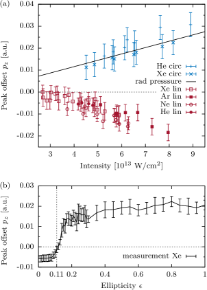
In order to minimize the influence of rescattering processes, we studied the projection of the PMD onto the beam propagation axis for the case of close-to-circular polarization for helium and xenon. We extract the zero momentum from reference images recorded with linear polarization as described in section II. The peaks of these projections were extracted via a Gaussian fit to the projection of the PMD onto the -axis. The results are shown together with a model from Ref. Smeenk et al. (2011) for circular polarization in Fig. 2. The results for circular polarization are consistent with the results from Ref. Smeenk et al. (2011) within the error bars. Theoretical studies predicted an additional offset of the order of at the tunnel exit Klaiber et al. (2013) as well as in the final momentum distributions Chelkowski et al. (2014); Cricchio et al. (2015); Chelkowski et al. (2015). However, the experiment cannot resolve this additional offset. In addition we show for comparison the data for linear polarization from Ref. Ludwig et al. (2014). The offsets for the case of linear polarization are shifted in contrast to the data for circular polarization opposite to the beam propagation direction.
The results with linear and circular polarization (Fig. 2 (a)) trigger the question what happens when the ellipticity is being changed? Since our previous results Ludwig et al. (2014) indicate that the non-dipole effects are independent of the target gas within the accuracy of our measurement. We therefore perform our studies on xenon. The ellipticity was varied in steps from linear to close-to-circular (). We ionized xenon atoms at an intensity of W/cm2 with 50-fs pulses at a center wavelength of 3.4 m. For each ellipticity step, projected momentum images in the (, ) plane were recorded. We would like to point out that during the measurement we kept the intensity constant, not the electric field. That allows us to keep the total momentum transfer per cycle onto a free electron from the field independent of the ellipticity. Fig. 11 shows how the projected PMD is evolving from the typical cigar-like shape with the major dimension in -direction towards a structure with maxima shifted to high values of . Furthermore, the spot in the center stemming from Rydberg-atoms ionized by the spectrometer field disappears with increasing ellipticity because the selection rules do not allow the excitation from the ground state into Rydberg states with circularly polarized light. Thus, reference measurements with linear polarization were taken right before and after each ellipticity step. The peaks for reference zero were extracted in a similar fashion as the method applied in Ref. Ludwig et al. (2014) and the one described in section II. For each reference measurement, we recorded photoelectron momentum images. The uncertainties of the determination of zero momentum scale with due to repetitive measurements that were weighted with the error for a Gaussian fit of the peak of each projected distribution.
The zero momentum reference was extracted from the momentum images with linear polarization from the peak of the projection of a thin slice of a.u. around projected onto the beam propagation. The peak of the projection was identified via a polynomial fit to the central part (i.e. a.u.). of the PMD , with being the integration momentum volume. The offset of that peak from is shown in Fig. 2(b) as a function of the ellipticity. We observe an increase of the offset with increasing ellipticity from negative values (i.e. opposite to the beam propagation direction) to positive values (i.e. in beam propagation direction). The transition from negative to positive values occurs at an ellipticity of . Thus, we have observed a zero-crossing along the -axis of the peak of the projected PMD as we scan the ellipticity.
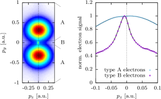
Next, we consider the role of Coulomb focusing in the electronic response to non-dipole effects. Thus we study the different responses of type A and type B electrons. Since we are able to isolate the electrons undergoing Coulomb-focusing in 3D momentum-space, we can study their response separately from the mostly unfocused electrons for . We select type B – electrons by choosing a narrow momentum range of 0.038 a.u. in direction from the 3D PMD recorded at an ellipticity of . The electron signal that lies within this range and the electron signal from outside this range are separately projected onto the -axis. The central spot stemming from ionization of Rydberg atoms was removed prior to the projections by removing the photoelectron signal with a.u.. The normalized projected electron signals are shown together in Fig. 12. The position of the peaks from A and type B electron signals on the -axis were identified. We observe that the type A electron signal peaks at a positive value of and the type B electron signal at a negative value of .
Increasing ellipticity supresses rescattering and thus, the PMD and its projection becomes dominated by electrons that interact only weakly with the Coulomb-potential of the parent ion. However, for ellipticities , the sharp ridge consisting of type B electrons starts to dominate the projection of the PMD onto the -axis. This creates a peak of electrons that significantly interact with the Coulomb-potential of the parent ion. That peak is shifted opposite to beam propagation direction.
VI Conclusions
In conclusion, we are able to separate the electrons that experienced strong Coulomb focusing in momentum space from the unfocused electrons in the case of elliptical polarization. With a detailed analysis, we identified a subspace in the momentum representation of the tunnel ionized electron wave packet, which in an elliptically polarized laser field shows recollision dynamics similar to the linear polarization case. The electron trajectories originating in this initial PMD subspace have multiple revisits, including at least one significant rescattering event with the parent ion, which causes the large initial momentum subspace to be squeezed into a small final momentum space having near vanishing transverse momentum. This effect occurs due to Coulomb focusing, and leads to the creation of the sharp ridge structure in momentum space for linear and small elliptical polarization. The final momenta of Coulomb-focused electrons that underwent slow recollisions, and hence experienced strong Coulomb focusing, are almost unaltered by the introduction of a small ellipticity. The ellipticity modifies the initial momenta of the electrons that end up in the ridge. We also learned that the central part of the tunnel ionized electron wave packet in momentum space provides electrons which are steered away by the elliptical polarization into elliptical side lobes of the final PMD. Thus we were able to separate the unfocused from the Coulomb-focused electrons.
Dispersion of the electron trajectories in final momentum was already reported in Shafir et al. (2013). However, there was no clear separation of the electrons undergoing Coulomb-focusing and the ones that interact only weakly with the Coulomb-field of the parent ion in momentum space. For small ellipticities we have shown that the electrons undergoing strong Coulomb-focusing accumulate in a sharp ridge in the 3D PMD that is largely separated from the unfocused electrons. This clear separation enables us to analyze non-dipole effects on Coulomb-focused electrons alone.
We use the full 3D PMD to study the different non-dipole response for both electrons with and without strong Coulomb-focusing. The separation of the electron trajectories allows us to disentangle the response of the photoelectrons from non-dipole effects and to make the connection between prior results Ludwig et al. (2014); Smeenk et al. (2011). In Ref. Smeenk et al. (2011), a shift of the PMD in beam propagation direction was reported and a simple radiation pressure picture was used as an explanation. In Ref. Ludwig et al. (2014), the peak of the projection of the PMD was shifted opposite to the beam propagation direction. Here, we were able to experimentally isolate the electrons that are responsible for this counterintuitive shift and to separately study their non-dipole response. We measured the ellipticity dependence of the non-dipole effects in PMDs in strong field ionization beyond the long-wavelength limit. We observed an offset of the maximum of the peak of the projection of the PMD on the beam propagation axis. By increasing the ellipticity from linear to circular, this offset shifts from negative to positive values of . Thus, we conclude that the formation of Coulomb-focused structures in PMDs in combination with the magnetic field causes peaks in negative -direction. The appearance of a peak on the negative or positive side of can be considered as a competition between two types of photoelectrons which we refer to as type A and type B electrons (Fig. 5). Type B photoelectrons form the sharp thin line-shaped ridge structure in the 3D PMD and type A photoelectrons are in the clearly separated lobes at higher final momentum. When we analyse the shift of the PMD peak along the laser beam propagation direction we could confirm that the type A electrons result in a positive shift and the type B electrons in a negative shift. In case that the peak is formed mainly by type A-electrons, the projection of the PMD peaks at positive values of whereas in the case that the type B electrons dominate the peak of the projected PMD, it is shifted towards negative values of . Thus, Coulomb focusing has an essential influence on non-dipole effects and creates an ellipticity-dependent PMD shift along the laser propagation direction on the ellipticity of the laser field.
Our results open up new possibilities to separately study the photoelectrons experiencing strong rescattering from the direct electrons and the electrons that experience only weak Coulomb interaction. Furthermore, as the occurrence of the Coulomb focusing effects also depend on the width of the returning electron wave packet, our studies open up the possibilities to gain insight into the precise structure of the returning electron wave packet.
Appendix A Derivation of the recollision conditions for elliptical polarization
We derive the condition under which the recollision parameters for elliptical polarization are similar to the ones for linear polarization.
The laser field given by Eqs. (1) and (2), the electron relativistic equations of motion in the polarization plane of the laser field, read:
| (18) | |||||
| (19) |
which is derived from Eqs. (3)-(4), using the relation , where , is the integral of motion in a plane laser field Di Piazza et al. (2012), and are the electron beta- (along the laser propagation direction) and gamma-factors, respectively. As the ionized electron appears at the tunnel exit with velocity much smaller than the speed of light, one has . The solution of Eqs. (18)-(19) is
| (20) | |||||
| (21) | |||||
where the initial coordinates at the ionization phase correspond to the tunnel exit:
| (22) | |||||
| (23) |
Considering the electrons contributing to the ridge in the case of linear polarization, the recollision -coordinate of the electron, ionized with the momentum , is
| (24) |
The momentum transfer upon recollision due to the Coulomb field is , and the final momentum of the electron is vanishing in the case of linear polarization
| (25) |
Consequently, , and
| (26) |
According to Eq. (21), the electron recollision coordinate in the case of elliptical polarization is
where is the initial Coulomb momentum transfer in the case of elliptical polarization and where we set . The momentum transfer during recollision in the case of elliptical polarization will be the same as in the case of linear polarization, , if the impact parameter is the same, i.e., if . The latter reads using Eqs. (A) and (24)
| (28) | |||||
where we have assumed that .
Appendix B Derivation of the diameter and position of the initial momenta for the ridge
We derive the equations for the center and the diameter of the ring of initial momenta contributing to a point on the ridge with . Let be the final momentum of an electron that started with from the left and the right part of the ring in initial momentum space, , respectively. We begin with the condition:
| (31) |
with
| (32) |
Using the expression for initial Coulomb momentum transfer: Liu and Hatsagortsyan (2010), , and the approximation the initial momenta are given by
| (33) |
From Eq. (31) follows that the diameter of the ring in the initial momentum distribution depends linearly on Coulomb momentum transfer during recollision:
| (34) |
The center of the ring is dependent on the ellipticity ,
| (35) |
and shifts to the right for increasing .
Appendix C Derivation of the conditions for initial phase
We can estimate the threshold of the ionization phase to have similarity of the recollision coordinate for linear and elliptical polarization, from the following condition:
| (36) |
with being the recollision coordinate at ellipticity . Using Eq. (21) and using the approximations and , this condition reads
| (37) |
which can be expressed via the Coulomb momentum transfer as:
| (38) |
The recollision phase is found from the condition . Taking into account that for the first recollision , with , we find
| (39) |
and the condition of Eq. (38), when the oscillating part of the -coordinate does not perturb the recollision coordinates significantly, is
| (40) |
For , we have .
Acknowledgements.
This research was supported by the NCCR MUST, funded by the Swiss National Science Foundation and by the ERC advanced grant ERC-2012-ADG 20120216 within the seventh framework programme of the European Union. Benjamin Willenberg was supported by an ETH Research Grant ETH-111̃5-1.References
- Popmintchev et al. (2012) T. Popmintchev, M. C. Chen, D. Popmintchev, P. Arpin, S. Brown, S. Alisauskas, G. Andriukaitis, T. Balciunas, O. D. Mucke, A. Pugzlys, A. Baltuska, B. Shim, S. E. Schrauth, A. Gaeta, C. Hernández-García, L. Plaja, A. Becker, M. M. Jaron-Becker, A .and Murnane, and H. C. Kapteyn, “Bright coherent ultrahigh harmonics in the keV x-ray regime from mid-infrared femtosecond lasers,” Science 336, 1287–1291 (2012).
- Huismans et al. (2011) Y. Huismans, A. Rouzée, A. Gijsbertsen, J. H. Jungmann, A. S. Smolkowska, P. S. W. M. Logman, F. Lépine, C. Cauchy, S. Zamith, T. Marchenko, J. M. Bakker, G. Berden, B. Redlich, A. F. G. van der Meer, H. G. Muller, W. Vermin, K. J. Schafer, M. Spanner, M. Y. Ivanov, O. Smirnova, D. Bauer, S. V. Popruzhenko, and M. J. J. Vrakking, “Time-resolved holography with photoelectrons,” Science (New York, N.Y.) 331, 61–64 (2011).
- Blaga et al. (2009) C.I. Blaga, F. Catoire, P. Colosimo, G.G. Paulus, H.G. Muller, P. Agostini, and L.F. DiMauro, “Strong-field photoionization revisited,” Nat. Phys. 5, 335–338 (2009).
- Quan et al. (2009) W. Quan, Z. Lin, M. Wu, H. Kang, H. Liu, X. Liu, J. Chen, J. Liu, X. T. He, S. G. Chen, H. Xiong, L. Guo, H. Xu, Y. Fu, Y. Cheng, and Z. Z. Xu, “Classical aspects in above-threshold ionization with a midinfrared strong laser field,” Phys. Rev. Lett. 103, 093001 (2009).
- Wolter et al. (2015) B. Wolter, M.G. Pullen, M. Baudisch, M. Sclafani, M.and Hemmer, A. Senftleben, C. D. Schröter, J. Ullrich, R. Moshammer, and J. Biegert, “Strong-field physics with mid-IR fields,” Phys. Rev. X 5, 021034 (2015).
- (6) The two- or three-step model of strong field ionization (Simple Man’s model) with purely classical propagation in the electric laser field neglecting the Coulomb potential, put forward independently by M. Yu. Kuchiev, JETP Lett. 45, 404 (1987); H. B. van Linden van den Heuvell and H. G. Muller, in Multiphoton Processes, ed. S. J. Smith and P. L. Knight, Cambridge University Press (1988); T. Gallagher, Phys. Rev. Lett. 61, 2304 (1988); K. J. Schafer, B. Yang, L. F. DiMauro, and K. C. Kulander, Phys. Rev. Lett. 70, 1599 (1993); P. B. Corkum, Phys. Rev. Lett. 71, 1994 (1993).
- Pfeifer et al. (2006) T. Pfeifer, Ch. Spielmann, and G. Gerber, “Femtosecond x-ray science,” Rep. Prog. Phys. 69, 443 (2006).
- McPherson et al. (1987) A. McPherson, G. Gibson, H. Jara, U. Johann, T. S. Luk, I. A. McIntyre, K. Boyer, and C. K. Rhodes, “Studies of multiphoton production of vacuum-ultraviolet radiation in the rare gases,” J. Opt. Soc. Am. B 4, 595–601 (1987).
- Ferray et al. (1988) M. Ferray, A. L’Huillier, X.F. Li, L.A. Lompre, G. Mainfray, and C. Manus, “Multiple-harmonic conversion of 1064 nm radiation in rare gases,” J. Phys. B 21, L31 (1988).
- Fittinghoff et al. (1992) D. N. Fittinghoff, P. R. Bolton, B. Chang, and K. C. Kulander, “Observation of nonsequential double ionization of helium with optical tunneling,” Phys. Rev. Lett. 69, 2642–2645 (1992).
- Walker et al. (1994) B. Walker, B. Sheehy, L. F. DiMauro, P. Agostini, K. J. Schafer, and K. C. Kulander, “Precision measurement of strong field double ionization of helium,” Phys. Rev. Lett. 73, 1227–1230 (1994).
- Feuerstein et al. (2001) B. Feuerstein, R. Moshammer, D. Fischer, A. Dorn, C. D. Schröter, J. Deipenwisch, J. R. Crespo Lopez-Urrutia, C. Höhr, P. Neumayer, J. Ullrich, H. Rottke, C. Trump, M. Wittmann, G. Korn, and W. Sandner, “Separation of recollision mechanisms in nonsequential strong field double ionization of Ar: The role of excitation tunneling,” Phys. Rev. Lett. 87, 043003 (2001).
- Agostini et al. (1979) P. Agostini, F. Fabre, G. Mainfray, G. Petite, and N. K. Rahman, “Free-free transitions following six-photon ionization of xenon atoms,” Phys. Rev. Lett. 42, 1127–1130 (1979).
- Blaga et al. (2012) C. I. Blaga, J. L. Xu, A. D. DiChiara, E. Sistrunk, K. K. Zhang, P. Agostini, T. A. Miller, L. F. DiMauro, and C. D. Lin, “Imaging ultrafast molecular dynamics with laser-induced electron diffraction,” Nature 483, 194–197 (2012).
- Brabec et al. (1996) T. Brabec, M. Y. Ivanov, and P. B. Corkum, “Coulomb focusing in intense field atomic processes,” Phys. Rev. A 54, R2551–R2554 (1996).
- Comtois et al. (2005) D. Comtois, D. Zeidler, H. Pépin, J. C. Kieffer, D. M. Villeneuve, and P. B. Corkum, “Observation of coulomb focusing in tunnelling ionization of noble gases,” Journal of Physics B: Atomic, Molecular and Optical Physics 38, 1923 (2005).
- Sasaki et al. (2009) K. Sasaki, X. M. Tong, and N. Toshima, “Coulomb focusing effect on the space distribution of the rescattering electron wavepacket in the laser-atom interaction,” J. Phys. B 42, 165603 (2009).
- Liu and Hatsagortsyan (2010) C. Liu and K. Z. Hatsagortsyan, “Origin of unexpected low energy structure in photoelectron spectra induced by midinfrared strong laser fields,” Phys. Rev. Lett. 105, 113003 (2010).
- Yan et al. (2010) T.-M. Yan, S. V. Popruzhenko, M. J. J. Vrakking, and D. Bauer, “Low-energy structures in strong field ionization revealed by quantum orbits,” Phys. Rev. Lett. 105, 253002 (2010).
- Huang et al. (2010) C. Huang, Q. Liao, Y. Zhou, and P. Lu, “Role of coulomb focusing on the electron transverse momentum of above-threshold ionization,” Opt. Expr. 18, 14293–14300 (2010).
- Liu and Hatsagortsyan (2011) C. Liu and K. Z. Hatsagortsyan, “Wavelength and intensity dependence of multiple forward scattering of electrons at above-threshold ionization in mid-infrared strong laser fields,” J. Phys. B 44, 095402 (2011).
- Kästner et al. (2012) A. Kästner, U. Saalmann, and J. M. Rost, “Electron-energy bunching in laser-driven soft recollisions,” Phys. Rev. Lett. 108, 033201 (2012).
- Lemell et al. (2012) C. Lemell, K. I. Dimitriou, X.-M. Tong, S. Nagele, D. V. Kartashov, J. Burgdörfer, and S. Gräfe, “Low-energy peak structure in strong-field ionization by midinfrared laser pulses: Two-dimensional focusing by the atomic potential,” Phys. Rev. A 85, 011403 (2012).
- Möller et al. (2014) M. Möller, F. Meyer, A. M. Sayler, G. G. Paulus, M. F. Kling, B. E. Schmidt, W. Becker, and D. B. Milošević, “Off-axis low-energy structures in above-threshold ionization,” Phys. Rev. A 90, 023412 (2014).
- Kelvich et al. (2016) S. A. Kelvich, W. Becker, and S. P. Goreslavski, “Coulomb focusing and defocusing in above-threshold-ionization spectra produced by strong mid-IR laser pulses,” Phys. Rev. A 93, 033411 (2016).
- Wang and Eberly (2009) X. Wang and J. H. Eberly, “Effects of elliptical polarization on strong-field short-pulse double ionization,” Phys. Rev. Lett. 103, 103007 (2009).
- Mauger et al. (2010) F. Mauger, C. Chandre, and T. Uzer, “Recollisions and correlated double ionization with circularly polarized light,” Phys. Rev. Lett. 105, 083002 (2010).
- Liu and Hatsagortsyan (2012) C. Liu and K. Z. Hatsagortsyan, “Coulomb focusing in above-threshold ionization in elliptically polarized midinfrared strong laser fields,” Phys. Rev. A 85, 023413 (2012).
- Shafir et al. (2013) D. Shafir, H. Soifer, C. Vozzi, A. S. Johnson, A. Hartung, Z. Dube, D. M. Villeneuve, P. B. Corkum, N. Dudovich, and A. Staudte, “Trajectory-resolved coulomb focusing in tunnel ionization of atoms with intense, elliptically polarized laser pulses,” Phys. Rev. Lett. 111, 023005 (2013).
- Li et al. (2014) M. Li, Y. Liu, H. Liu, Q. Ning, L. Fu, J. Liu, Y. Deng, C. Wu, L.-Y. Peng, and Q. Gong, “Publisher’s note: Subcycle dynamics of coulomb asymmetry in strong elliptical laser fields [phys. rev. lett. 111, 023006 (2013)],” Phys. Rev. Lett. 112, 189901 (2014).
- Pullen et al. (2015) M. G. Pullen, B. Wolter, A.-T. Le, M. Baudisch, M. Hemmer, A. Senftleben, C. D. Schröter, J. Ullrich, R. Moshammer, C.-D. Lin, and J. Biegert, “Imaging an aligned polyatomic molecule with laser-induced electron diffraction,” Nat. Commun. 6, 7262 (2015).
- Keitel and Knight (1995) C. H. Keitel and P. L. Knight, “Monte carlo classical simulations of ionization and harmonic generation in the relativistic domain,” Phys. Rev. A 51, 1420–1430 (1995).
- Walser et al. (2000) M. W. Walser, C. H. Keitel, A. Scrinzi, and T. Brabec, “High harmonic generation beyond the electric dipole approximation,” Phys. Rev. Lett. 85, 5082–5085 (2000).
- Milošević et al. (2000) D. B. Milošević, S. Hu, and W. Becker, “Quantum-mechanical model for ultrahigh-order harmonic generation in the moderately relativistic regime,” Phys. Rev. A 63, 011403 (2000).
- Kylstra et al. (2001) N. J. Kylstra, R. M. Potvliege, and C. J. Joachain, “Photon emission by ions interacting with short intense laser pulses: beyond the dipole approximation,” J. Phys. B 34, L55 (2001).
- Reiss (2008) H. R. Reiss, “Limits on tunneling theories of strong-field ionization,” Phys. Rev. Lett. 101, 043002 (2008).
- Kohler et al. (2012) M.C. Kohler, T. Pfeifer, K.Z. Hatsagortsyan, and C.H. Keitel, “Chapter 4 - frontiers of atomic high-harmonic generation,” in Adv. At. Mol. Phys., Vol. 61, edited by E. Arimondo P. Berman and C. Lin (Academic Press, 2012) pp. 159 – 208.
- Smeenk et al. (2009) C. Smeenk, L. Arissian, A. Staudte, D.M. Villeneuve, and P.B. Corkum, “Momentum space tomographic imaging of photoelectrons,” J. Phys. B 42, 185402 (2009).
- Klaiber et al. (2013) M. Klaiber, E. Yakaboylu, H. Bauke, K. Z. Hatsagortsyan, and C. H. Keitel, “Under-the-barrier dynamics in laser-induced relativistic tunneling,” Phys. Rev. Lett. 110, 153004 (2013).
- Chelkowski et al. (2014) S. Chelkowski, A. D. Bandrauk, and P. B. Corkum, “Photon momentum sharing between an electron and an ion in photoionization: From one-photon (photoelectric effect) to multiphoton absorption,” Phys. Rev. Lett. 113, 263005 (2014).
- Cricchio et al. (2015) D. Cricchio, E. Fiordilino, and K. Z. Hatsagortsyan, “Momentum partition between constituents of exotic atoms during laser-induced tunneling ionization,” Phys. Rev. A 92, 023408 (2015).
- Chelkowski et al. (2015) S. Chelkowski, A. D. Bandrauk, and P. B. Corkum, “Photon-momentum transfer in multiphoton ionization and in time-resolved holography with photoelectrons,” Phys. Rev. A 92, 051401 (2015).
- Dammasch et al. (2001) M. Dammasch, M. Dörr, U. Eichmann, E. Lenz, and W. Sandner, “Relativistic laser-field-drift suppression of nonsequential multiple ionization,” Phys. Rev. A 64, 061402 (2001).
- Klaiber et al. (2005) M. Klaiber, K. Z. Hatsagortsyan, and C. H. Keitel, “Above-threshold ionization beyond the dipole approximation,” Phys. Rev. A 71, 033408 (2005).
- DiChiara et al. (2008) A. D. DiChiara, I. Ghebregziabher, R. Sauer, J. Waesche, S. Palaniyappan, B. L. Wen, and B. C. Walker, “Relativistic MeV Photoelectrons from the single atom response of argon to a laser field,” Phys. Rev. Lett. 101, 173002 (2008).
- Ekanayake et al. (2013) N. Ekanayake, S. Luo, P. D. Grugan, W. B. Crosby, A. D. Camilo, C. V. McCowan, R. Scalzi, A. Tramontozzi, L. E. Howard, S. J. Wells, C. Mancuso, T. Stanev, M. F. Decamp, and B. C. Walker, “Electron shell ionization of atoms with classical, relativistic scattering,” Phys. Rev. Lett. 110, 203003 (2013).
- Palaniyappan et al. (2006) S. Palaniyappan, I. Ghebregziabher, A. DiChiara, J. MacDonald, and B. C. Walker, “Emergence from nonrelativistic strong-field rescattering to ultrastrong-field laser-atom physics: A semiclassical analysis,” Phys. Rev. A 74, 033403 (2006).
- Førre et al. (2006) M. Førre, J. P. Hansen, L. Kocbach, S. Selstø, and L. B. Madsen, “Nondipole ionization dynamics of atoms in superintense high-frequency attosecond pulses,” Phys. Rev. Lett. 97, 043601 (2006).
- Ludwig et al. (2014) A. Ludwig, J. Maurer, B. W. Mayer, C. R. Phillips, L. Gallmann, and U. Keller, “Breakdown of the dipole approximation in strong-field ionization,” Phys. Rev. Lett. 113, 243001 (2014).
- Smeenk et al. (2011) C. T. L. Smeenk, L. Arissian, B. Zhou, A. Mysyrowicz, D. M. Villeneuve, A. Staudte, and P. B. Corkum, “Partitioning of the linear photon momentum in multiphoton ionization,” Phys. Rev. Lett. 106, 193002 (2011).
- Eppink and Parker (1997) A. T. J. B. Eppink and D. H. Parker, “Velocity map imaging of ions and electrons using electrostatic lenses: Application in photoelectron and photofragment ion imaging of molecular oxygen,” Rev. Sci. Instrum. 68, 3477–3484 (1997).
- Parker and Eppink (1997) D. H. Parker and A. T. J. B. Eppink, “Photoelectron and photofragment velocity map imaging of state-selected molecular oxygen dissociation/ionization dynamics,” J. Chem. Phys 107, 2357–2362 (1997).
- Ghafur et al. (2009) O. Ghafur, W. Siu, P. Johnsson, M. F. Kling, M. Drescher, and M. J. J. Vrakking, “A velocity map imaging detector with an integrated gas injection system,” Rev. Sci. Instrum. 80 (2009), http://dx.doi.org/10.1063/1.3085799.
- Weger et al. (2013) M. Weger, J. Maurer, A. Ludwig, L. Gallmann, and U. Keller, “Transferring the attoclock technique to velocity map imaging,” Opt. Expr. 21, 21981–21990 (2013).
- Mayer et al. (2013) B. W. Mayer, C. R. Phillips, L. Gallmann, M. M. Fejer, and U. Keller, “Sub-four-cycle laser pulses directly from a high-repetition-rate optical parametric chirped-pulse amplifier at 3.4 m,” Opt. Lett. 38, 4265–4268 (2013).
- Mayer et al. (2014) B. W. Mayer, C. R. Phillips, L. Gallmann, and U. Keller, “Mid-infrared pulse generation via achromatic quasi-phase-matched OPCPA,” Opt. Expr. 22, 20798–20808 (2014).
- Pfeiffer et al. (2012) A. N. Pfeiffer, C. Cirelli, M. Smolarski, D. Dimitrovski, M. Abu-samha, L. B. Madsen, and U. Keller, “Attoclock reveals natural coordinates of the laser-induced tunnelling current flow in atoms,” Nat. Phys. 8, 76 (2012).
- Nubbemeyer et al. (2008) T. Nubbemeyer, K. Gorling, A. Saenz, U. Eichmann, and W. Sandner, “Strong-field tunneling without ionization,” Phys. Rev. Lett. 101, 233001 (2008).
- Wollenhaupt et al. (2009) M. Wollenhaupt, M. Krug, J. Köhler, T. Bayer, C. Sarpe-Tudoran, and T. Baumert, “Three-dimensional tomographic reconstruction of ultrashort free electron wave packets,” Appl. Phys. B 95, 647–651 (2009).
- Dimitrovski et al. (2014) D. Dimitrovski, J. Maurer, H. Stapelfeldt, and L. B. Madsen, “Low-energy photoelectrons in strong-field ionization by laser pulses with large ellipticity,” Phys. Rev. Lett. 113, 103005 (2014).
- Eckle et al. (2008a) P. Eckle, M. Smolarski, F. Schlup, J. Biegert, A. Staudte, M. Schöffler, H. G. Muller, R. Dörner, and U. Keller, “Attosecond angular streaking,” Nat. Phys. 4, 565 (2008a).
- Eckle et al. (2008b) P. Eckle, A. N. Pfeiffer, C. Cirelli, A. Staudte, R. Dörner, H. G. Muller, M. Büttiker, and U. Keller, “Attosecond ionization and tunneling delay time measurements in helium,” Science 322, 1525–1529 (2008b).
- Bashkansky et al. (1988) M. Bashkansky, P. H. Bucksbaum, and D. W. Schumacher, “Asymmetries in above-threshold ionization,” Phys. Rev. Lett. 60, 2458–2461 (1988).
- Landsman et al. (2014) A.S. Landsman, M. Weger, J. Maurer, R. Boge, A. Ludwig, S. Heuser, C. Cirelli, L. Gallmann, and U. Keller, “Ultrafast resolution of tunneling delay time,” Optica 1, 343–349 (2014).
- Perelomov and Popov (1967) A. M. Perelomov and V. S. Popov, “Ionization of atoms in an alternating electrical field. III,” Zh. Exp. Theor. Fiz. 52, 514 (1967).
- Ammosov et al. (1986) M. V. Ammosov, N. B. Delone, and V. P. Krainov, “Tunnel ionization of complex atoms and of atomic ions in an alternating electromagnetic field,” Zh. Eksp. Teor. Fiz. 91, 2008 (1986).
- Delone and Krainov (1991) N. B. Delone and V. P. Krainov, “Energy and angular electron spectra for the tunnel ionization of atoms by strong low-frequency radiation,” J. Opt. Soc. Am. B 8, 1207–1211 (1991).
- (68) Here, we refer to the theory of tunnel ionization in the quasistatic limit. Commonly, this case is reffered to as the Ammosov-Delone-Kraĭnov (ADK). The results of this theory are already contained in the Perelomov-Popov-Terent’ev (PPT)-theory as the limit for the a zero-frequency field.
- Shvetsov-Shilovski et al. (2009) N. Shvetsov-Shilovski, S. Goreslavski, S. Popruzhenko, and W. Becker, “Capture into rydberg states and momentum distributions of ionized electrons,” Las. Phys. 19, 1550–1558 (2009).
- Di Piazza et al. (2012) A. Di Piazza, C. Müller, K. Z. Hatsagortsyan, and C. H. Keitel, “Extremely high-intensity laser interactions with fundamental quantum systems,” Rev. Mod. Phys. 84, 1177–1228 (2012).