Design and Development of an automated Robotic Pick & Stow System for an e-Commerce Warehouse
Abstract
In this paper, we provide details of a robotic system that can automate the task of picking and stowing objects from and to a rack in an e-commerce fulfillment warehouse. The system primarily comprises of four main modules: (1) Perception module responsible for recognizing query objects and localizing them in the 3-dimensional robot workspace; (2) Planning module generates necessary paths that the robot end-effector has to take for reaching the objects in the rack or in the tote; (3) Calibration module that defines the physical workspace for the robot visible through the on-board vision system; and (4) Gripping and suction system for picking and stowing different kinds of objects. The perception module uses a faster region-based Convolutional Neural Network (R-CNN) to recognize objects. We designed a novel two finger gripper that incorporates pneumatic valve based suction effect to enhance its ability to pick different kinds of objects. The system was developed by IITK-TCS team for participation in the Amazon Picking Challenge 2016 event. The team secured a fifth place in the stowing task in the event. The purpose of this article is to share our experiences with students and practicing engineers and enable them to build similar systems. The overall efficacy of the system is demonstrated through several simulation as well as real-world experiments with actual robots.
Index Terms:
Warehouse automation, object recognition, R-CNN, pose estimation, motion planning, pick and place robot, visuo-motor coordination.I Introduction
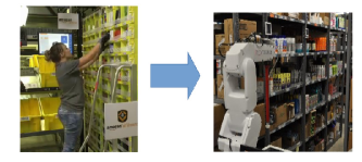
Warehouses are important links in the supply chain between the manufacturers and the end consumers. People have been increasingly adopting automation to increase the efficiency of managing and moving goods through warehouses [1]. This is becoming even more important for e-commerce industries like Amazon [2] that ships millions of items to its customers worldwide through its network of fulfillment centres. These fulfillment centres are sometimes are big as nine football pitches [3] employing thousands of people for managing inventories. While these warehouses employ IoT and IT infrastracture [4, 5] to keep track of goods moving in and out of the facility, it still requires the staffs to travel several miles each day in order to pick or stow products from or to different racks [3]. The problem related to the goods movement was solved by the introduction of mobile platforms like KIVA systems [6] that could carry these racks autonomously to human ‘pickers’ who would then, pick things from these racks while standing at one place. These mobile platforms could then be programmed [7] [8] to follow desired paths demarcated using visual [9] or magnetic markers [10]. However, it still needs people to pick or stow items from or to these racks. Amazon hires several hundred people during holiday seasons, like Christmas or New Year, to meet this increased order demands. Given the slimmer operating margins, e-commerce industries can greatly benefit from deploying robotic ‘pickers’ that can replace these humans. This transition is illustrated in Figure 1. The left hand side of this figures shows the current state of affairs where a human picks or stows items from or to the racks, which are brought to the station by mobile platforms. The right hand side of this figure shows the future where robots will be able to do this task autonomously. In the later case, it won’t be required to bring the racks to a picking station anymore if the robot arm is itself mounted on a mobile platform [11]. However, building such robots that can pick / stow items from / to these racks with the accuracy, dexterity and agility of a human picker is still far too challenging. In order to spur the advancement of research and development in this direction, Amazon organizes annual competition known as ‘Amazon Picking Challenge’ [12] every year since 2015. In this competition, the participants are presented with a simplified version of the problem where they are required to design robots that can pick and stow items autonomously from or to a given rack.
The picking task involves moving items from a rack and place them into a tote while the stowing task involves moving items from the tote to the rack. The objects to be picked or stowed are general household items that varies greatly in size, shape, appearance, hardness and weight. Since there is no constraint on how the products are organized on the rack or the tote, there are several possibilities of configuration one might encounter during the actual operation. This uncertainty that may arise due to factors like occlusion, variation in illumination, pose, viewing angle etc. makes the problem of autonomous picking and stowing extremely challenging.
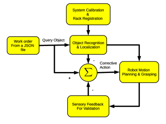
This paper provides the details of the proposed system that can accomplish this task and share our experiences of participating in the APC 2016 event held in Leipzig, Germany. The proposed system primarily consists of three main modules: (1) Calibration, (2) Perception, (3) Motion Planning as shown in Figure 2. Some of the distinctive features of our implementation are as follows. In contrast to other participants, we took a minimalistic approach making use of minimum number of sensors necessary to accomplish the task. These sensors were mounted on the robot itself and the operation did not require putting any sensor in the environment. Our motivation has been to develop robotic systems that can work in any environment without requiring any modification to the existing infrastructure. The second distinctive feature of our approach was our lightweight object recognition system that could run on a moderate GPU laptop. The object recognition system uses a trained Faster RCNN based deep network [13] to recognize objects in an image. Deep network requires large number of training examples for higher recognition accuracy. The training examples are generated and annotated through a laborious manual process requiring considerable amount of time and effort. Moreover, larger training set requires larger time for training the network for a given GPU configuration. In a deviation to the usual trend, a hybrid method is proposed to reduce the number of training examples required for obtaining a given detection accuracy. Higher detection accuracy corresponds to tighter bounding box around the target object while lesser training examples will result in bigger bounding box around the target object. The exact location for making contact with the object within this bounding box is computed using an algorithm that uses surface normals and depth curvatures to segment the target object from its background and finds suitable graspable affordance to facilitate its picking. In other words, the limitations of having smaller training set is overcome by an additional step which uses depth information to localize the targets within the bigger bounding box obtained from the RCNN network. This is another step which helps us in maintaining our minimalistic approach towards solving the problem. This approach allowed us to achieve accuracy of about in object recognition by training the RCNN network using only 5000 images as opposed to other participants who used more than 20,000 images and high end GPU machines. The third distinctive feature of this paper is the details that has been put in to explain the system integration process which, we believe, would be useful for students, researchers and practicing engineers in reproducing and replicating similar systems for other applications.
In short, the major contributions made in this paper could be summarized as follows: (1) a novel hybrid perception method is proposed where depth information is used to compensate for the lesser size of dataset required for a training a deep network based object recognition system. (2) The proposed system uses minimal resources to accomplish the complete task. It essentially uses only one Kinect sensor in a Eye-in-hand configuration for all perception task in contrast to others [14] who used expensive camera like Ensenso [15]. (3) An innovative gripper design is provided that combines both suction as well as gripping action. (4) A detailed description of the system implementation is provided which will be useful for students, researchers and practicing engineers. The performance of the proposed system is demonstrated through rigorous simulation and experiments with actual systems. The current system can achieve a pick rate of approximately 2-3 objects per minute.
The rest of this paper is organized as follows. An overview of various related work is provided in the next section. A formal definition of the problem to be solved in this paper is described in Section II. The system architecture and schematic of the system that is developed to solve this problem is described in Section III. The details of methods for each of these modules are described in detail in Section IV. The system performance as well as the results of various experiments are provided in Section V. The conclusion and direction for future work is provided in Section VI.
II Problem definition
As described before the objective of this work is to replace humans for picking and stowing tasks in an e-commerce warehouse as shown in Figure 1. The schematic block diagram of our proposed system which can accomplish this objective is shown in Figure 2. The list of items to be picked or stowed is provided in the form of a JSON file. The system comprises of a rack, a tote and a 6 DOF robotic arm with appropriate vision system and end-effector for picking items from the rack or the tote.
The task is to develop a robotic system that can automatically pick items from a rack and put them in a tote and vice-versa. The reverse task is called the stowing task. The information about the rack as well as the objects to be picked or stowed are known apriori. The rack specified by APC 2016 guidelines had 12 bins arranged in a 43 grid. There were about 40 objects in total which were provided to each of the participating teams.
In the pick task, the robot is expected to move items from the shelves of a rack to a tote. A subset of the 40 objects (known apriori) were randomly distributed in these 12 bins. Each bin would contain minimum of one and maximum of 10 items and the list of items at individual bins are known. Multiple copies of the same item could be placed in the same bin or in different bin. The bins may contain items which are partially occluded or in contact with other items or the wall of the bin. In other words, there is no constraint on how the objects would be placed in these bins. A json file is given prior to start the task which contain the details about which item is in which bin and what items are to be picked up from these bins. The task is to pick 12 specified items, only one from each of the bin in any sequence and put it into the tote.
In the stow task, the robot is supposed to move items from a tote and place them into bins on the shelf. The tote contained 12 different items, which are placed in such a way that some items are fully occluded or partially occluded by other items. The rest of the items are placed in the bins so that each bin can have minimum one item and maximum 10 items. The task is to stow 12 items from the tote one by one in any sequence and put them into any bin.
The challenge was to get the robot to pick or stow autonomously as many items as it could within 15 minutes. Different objects carried different reward points if they were picked or stowed successfully. Penalty was imposed on making mistakes such as picking or stowing wrong items, dropping them midway or damaging the items or the rack during robot operation etc.
III System Architecture
The schematic block diagram of the complete system is shown in Figure 2. The system reads the query items one by one from a JSON file. The JSON file also provides the bin location for each of these queried items. The robot has to pick these items from their respective bins. Since there could be several other objects in the bin, robot has to identify and localize the target object inside these bins. The system consists of the following three main components: (1) Calibration module, (2) Perception module, and (3) Motion planning module. The calibration module is used for defining the workspace of the robot with respect to the rack and the tote. It computes the necessary transformations needed for converting image features into physical real world coordinates. The perception module is responsible for recognizing queried items, localize them in the bin and find the respective physical coordinates which can be used by robot for motion planning. The motion planning module generates necessary robot configuration trajectories and motion to reach the object, pick it using suction or gripping action and move it to a tote. This module makes use of several sensors to detect the completion of the task. Once the task is completed, the system moves to the next item in the JSON query list.
The system is implemented using Robot Operating System (ROS) framework [16]. The operation of the complete system is divided into different modules each performing a specific task. Each of these modules are made available as a node which are the basic computation units in a ROS environment. These nodes communicate with each other using topics, services and parameter servers. Readers are advised to go through basic ROS tutorials available online111http://wiki.ros.org/ROS/Tutorials in order to understand these concepts before proceeding further. Topics are unidirectional streaming communication channels where data is continuously published by the generating node and other nodes can access this data by subscribing to this topic. In case, nodes are required to receive a response from other nodes, it can be done through services. The complete set of modules which are required for building the complete system is shown in Figure 3. These modules or nodes run on different computing machines which are connected to a common LAN. The dotted line indicate service calls which execute a particular task on demand basis. All these modules are controlled by a central node named “apc_controller”. Simulation environment and RVIZ visualizer is also part of this system and is made available as an independent node.
IV The Methods
In this section, we provide the details of underlying methods for each of the modules described in the previous section.
IV-A System Calibration
The calibration step is needed to define the workspace of the robot as seen through a camera so that the robot can reach any visible location in the workspace. The calibration is an important step in all robotic systems that use camera as a sensor to perceive the environment. The purpose is to the transform the points visible in the camera plane to the physical Cartesian plane. A number of methods have been devised for calibration the normal RGB cameras [17] [18] which try to estimate the camera parameters so that the required transformation from pixel coordinates to 3D Cartesian coordinates could be carried out. The depth estimation has been simplified with the advent of RGBD camera such as Kinect [19] [20] which provides depth value for each RGB pixel of the image frame.
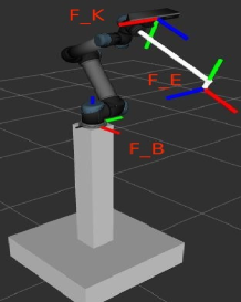
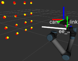
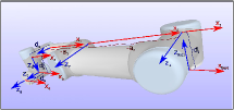
In this work, a Kinect RGBD camera is used in eye-in-hand configuration to detect as well as find the Cartesian coordinate of a query object with respect to its frame . These coordinates are required to be transformed into robot base frame coordinate so that it can be reached by the robot. In order to do this, it is necessary to know the transformation between the Kinect camera frame and the robot end-effector frame . The corresponding frames are shown in Figure 4. The transformation between the frames and is known through the forward kinematics of the robot manipulator. Hence the calibration step aims at finding this transformation between the robot end effector frame and the Kinect frame as explained below.
Let us consider a set of points which are recorded with respect to the Kinect frame . The same set of points as recorded with respect to the robot base frame is represented by . These later points are obtained by moving the robot so that the robot end-effector touches these points which are visible in the Kinect camera frame. Since these two sets refer to the same set of physical locations, the relation between them may be written as
| (1) |
where denotes the corresponding Rotation and translation needed for the transformation between the coordinate frames. These equations are solved for using least square method based on Singular Value Decomposition (SVD) [21] [22] as described below.
The centroid of these points is given by
and the corresponding Covariance matrix is given by
| (2) |
Given SVD of covariance matrix , the rotation matrix and translation vector are given by
| (3) | |||||
| (4) |
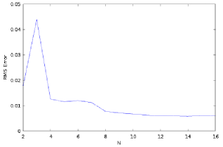
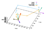
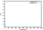
The RMS error between the actual points and the points computed using estimated is shown in Figure 5 and the corresponding points are shown in Figure 6. The points are shown with respect to the robot base coordinate frame. The red points are the actual points and the yellow points are computed using estimated values of . It is possible to obtain an RMS error of 1 cm with as small as 8 points.
IV-B Rack detection
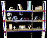
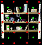
Rack detection involves finding the corners of the rack and the bin centers automatically from an RGBD image recorded by the on-board Kinect camera. The bin corners information is useful for defining region of interest (ROI) for identifying objects within the bin. The bin corners and centres are also useful for planning motion to and inside the bins for picking objects. The bins in the rack are in form of a grid structure consisting of 4 vertical and 5 horizontal lines, and hence the bin corners can be identified by the intersection of vertical and horizontal lines. The vertical and the horizontal lines on the rack are detected using Hough line transform [23]. If are end points of a vertical line and are end points of a horizontal line then the equation222https://en.wikipedia.org/wiki/Line-line_intersection to compute the intersection of the two lines is given by
Once the corners are known, the bin centre can be computed as the mean of its centres. The Figure 7(a) shows the vertical and horizontal lines detected using an OpenCV [24] implementation for Hough transform 333 http://docs.opencv.org/2.4/doc/tutorials/imgproc/imgtrans/hough_lines/hough_lines.html. The intersection points computed using above equations are shown in Figure 7(b) where the bin corners are shown in red while the bin centres are shown in green. Note that only three middle horizontal lines and two outer vertical lines are required to be detected. Rest of the points can be estimated using the prior knowledge of rack geometry.
IV-C Object Recognition
Recognition and localization of an object in an image have been a fundamental and challenging problems in computer vision since decades [25, 26, 27, 28]. In the era of deep learning, CNN has been widely used for object recognition task and it has shown outstanding performance [29, 30, 13, 31] as compared to the conventional hand-crafted feature based object recognition techniques [27, 28]. Techniques, like deformable parts models (DPM) [32] uses a sliding window method where at every evenly spaced spatial location the classifier is trained. The approach hence fails to progress further due to huge computational complexity. Eventually, in R-CNN was introduced by Girshick et al. [33], which use region proposal methods to generate potential bounding boxes at the first stage. Then the classifier is trained on each of these proposed boxes. The bounding boxes are fine-tunned by post-processing followed by eliminating duplicate detection and re-evaluating the box based on objects in the scene. There are other variants of R-CNN with improved recognition accuracy and faster execution time. Some of theses are presented in [34, 13, 35].
In a recent work Redmon et al. proposes you only look once (YOLO) [35], where the object detection is transformed to a single regression problem. The approach improves the performance in terms of computational cost, however, the recognition accuracy is slightly inferior as compared to the Faster RCNN [13]. We use Faster RCNN as a base for our object recognition and localization task, as it localizes the objects in an image in real-time with very high recognition accuracy.
In APC 2016, object detection is considered to be a challenging problem due to varying illumination conditions, placement of the objects in different orientation and depths inside the rack. In case of stowing, the objects in the tote can be fully or partially occluded by other objects. These, resulted in a very complex object recognition task.
We have combined the deep learning approach and standard image processing techniques for robust object detection. We are using Faster RCNN based deep neural network to find the bounding box of the target object. A second step verification of target object in the bounding box provided by RCNN is performed using random forest classifier. We have done fine tuning of pretrained object detection model with our own dataset. The details of the data preparation, training and verification step are given in the below sections.
Annotation: We have prepared two different training datasets for picking and stowing task. We have annotated 150 RGB images per object with different orientations and backgrounds for each task. A total of 6000 images were annotated for each task.
Training models: To do object detection task, which includes classification and localisation, we are using VGG-16 layered classification network in combination with Region proposal Networks. RPN are basically fully covolutional network which takes an image as input and outputs a set of rectangular object proposals, each with an objectness score. It is a 16 layered classification network which consists of 13 convolution layers and 3 fully connected layers. These RPN share convolutional layers with object detection networks due to which it does not add significant computation at run time( 10ms per image). We have fine tuned VGG-16 pretrained model of faster RCNN for our own dataset of 6000 images for 40 different objects.
Object Verification: We have added an additional step in object detection pipeline to verify object in the window proposed by RCNN. It uses shape and color information to verify the presence of the object. Both shape and color informations are incorporated as a feature vector and a random forest is used to classify each pixel inside the object box. After finding the most probable region inside the window using random forest, we apply a meanshift algorithm to obtain the suction point for that object. The details of the feature (shape and color) and classifier used are explained below:
Shape and color information as a feature: As we know, any 3D surface of the object is characterized by the surface normals at each point in the pointcloud. The angle between neighboring normals at interest points on any suface can be used to the shape of any object. A shape histogram is created for each object model which is used as a shape feature vector. Similarly, we are incorporating color information in the feature using color and grayscale histogram of the objects.
Random Forest: After computing histograms, all three histograms are concatenated as a 37 dimensional feature vector for each object. The training data is prepared by extracting features from pointcloud and RGB data for each object. A Random forest classifier is trained for each object with One vs all strategy. In one vs all, the target object features are trained as positive class and rest all features are considered as negative class. The number of trees and depth of the trees used in the random forest are 100 and 30 respectively.

IV-D Grasping

Grasping involves two steps - finding grasp pose for the target object then making actual motion to make physical contact with the object. The first part is usually difficult and has attracted a lot of attention over last couple of decades. There are primarily two approaches to solve the grasping problem - one of them makes use of known 3D CAD models [36] and the other one which does not require these CAD models [37] [38] [39]. The latter method directly works on the partial depth point cloud obtained from a range sensor. Quite recently, researchers are exploring the use of deep learning networks to detect grasping directly from images [40] [41].
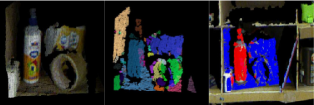
In this paper we follow the latter approach where we detect the graspable affordance for the recognized object directly from the RGBD point cloud obtained from the on-board Kinect camera. Figure 10 shows the schematic block diagram of the method employed for grasp pose detection. Input to this scheme is an RGBD point cloud of the bin viewed by the on-board robot camera. The bounding box of the query object is obtained by the RCNN based object recognition system. The bounding box returned by the RCNN module may have a bigger size than the object itself depending on the amount of training of the network used. This bounding box acts as the region of interest (ROI) for finding graspable regions. This bounding box may contain parts of the background as well other objects in the vicinity. Within this ROI, a clustering method combined with region growing algorithm [42] [43] is used to create several surface segments by identifying discontinuity in the space of surface normals [44] [45] [46]. Apart from having different surfaces for different objects and backgrounds, there can be multiple surface segments for the same object. Then the background segments are separated from the foreground target segments using a Gaussian Mixture Model (GMM) [47] [47] of the identified object using both color (RGB) and depth curvature information. Once the background segments are discarded, a primitive shape is identified for the object using empirical rules based on surface normals, radius of curvature, alignment of surfaces etc. Once the shape is identified, the best graspable affordance for the object is computed using a modified version of the method presented in [47]. The complete details for the method is beyond the scope of this paper and will be made available as a separate publication. The outcome of this algorithm is discussed in the experiment section later in this paper.
IV-E Motion Planning
In case of industrial manipulators where one does not have access to internal motor controllers, motion planning refers to providing suitable joint angle position (or velocity) trajectories needed for taking the robot from one pose to another. In other words, motion planning becomes a path planning problem which is about finding way point poses between the current pose and the desired end-effector pose. The problem of generating collision free paths for manipulators with increasingly larger number of links is quite complex and has attracted considerable interest over last couple of decades. Readers can refer to [48] for an overview of these methods. These methods could be primarily divided into two categories - local and global. Local methods start from a given initial configuration and step towards final configuration by using local information of the workspace. Artificial potential field-based methods [49] [50] [51] are one such category of methods where the search is guided along the negative gradient of artificially created vector fields. On the other hand, global methods use search algorithms over the entire workspace to find suitable paths. Some of the examples of global methods are probabilistic roadmaps (PRM) [52] [53]and Cell-decomposition based C-Space methods [54] [55]. Rapidly exploring random tree (RRT) [56] is one of the most popular PRM method used for path planning. Many of these state-of-the-art algorithms are available in the form of the open motion planning library (OMPL) [57] which has been integrated into several easy-to-use software packages like Moveit! [58], Kautham [59] and OpenRave [60].
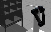
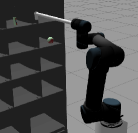
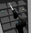
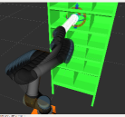
In this paper, we have used Moveit! package available with ROS [16] for building motion planning algorithms for UR5 robot manipulator. The simulation is carried out using Gazebo [61] environment. Some of the snapshots of the robot are shown in Figure 11. The robot starts its operation from its home pose which is shown in Figure 11(a). The pose is so selected so that the entire rack is visible from the on-board Kinect camera (not shown in the picture). This image is used for system calibration process as described in Section IV-A and IV-B respectively. Once the bin number is obtained from the JSON query file, the robot moves to the bin view pose shown in Figure 11(b). At this pose, a close up picture of the bin is taken by the Kinect camera mounted on the wrist of the robot. Every bin has a pre-defined bin view pose which is selected so as to get a good view of the bin. The desired pose necessary for picking an item in the bin is obtained from the object recognition and grasping algorithm. One such desired pose is shown in Figure 11(c). The robot configuration trajectory generated by the motion planning algorithm is shown in Figure 11(d). It also performs collision avoidance by considering the rack (shown in green color) as an obstacle.
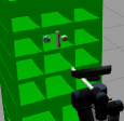
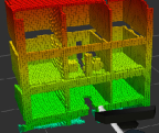
The sequence of steps involved in carrying out motion planning for the pick task is shown in Figure 12. It primarily involves four steps. The motion for segments 1 and 4 are executed using pre-defined joint angles as these poses do not change during the pick task. However, the motion planning for segment 2 (pre-grasp motion) and segment 3 (post-grasp motion) is carried out using RRT algorithm during the run-time. This is because the desired pose required for grasping the object will vary from one object to another and hence, the paths are required to be determined in the run-time. The on-line motion planning uses flexible collision library (FCL) [62] to generate paths for robot arm that avoid collision with the rack as well as the objects surrounding the target item. In order to avoid collision with the rack, the bin corners obtained from the rack detection module, described in Section IV-B, is used to define primitive boxes for each wall of the bin. These primitive boxes, shown in green color in Figure 13(a), are then treated as obstacles in the motion planning space. Similarly, the collision with other objects in the bin is achieved by creating 3D occupancy map called OctoMap [63] which converts point cloud into 3D voxels. This OctoMap feed is added to the Moveit motion planning scene and FCL is used for avoiding collision with the required objects. The OctoMap output of a 3D point cloud is shown in Figure 13(b).

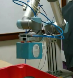
IV-F End-effector Design
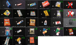
Amazon Picking Challenge focusses on solving the challenges involved in automating picking and stowing various kinds of retail goods using robots. These items include both rigid as well as deformable objects of varied shape and size. The maximum specified weight was about 1.5 Kgs. A snapshot of typical objects that were specified for the APC 2015 event [12] is shown in Figure 14. The authors in [64] provide a rich dataset for these objects which can be used for developing algorithms for grasping and pose estimation. It was necessary to design an end-effector which could grasp or pick all kinds of objects. We designed two kinds of end-effectors to solve this problem which are described below.
IV-F1 Suction-based end-effector
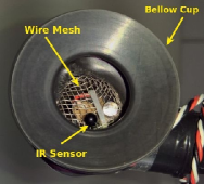
This end-effector essentially makes use of a vacuum suction system to pull the objects towards it and hold it attached to the end-effector. Such a system was successfully used by the TU-Berlin team [65] in the APC 2015 event where they came out as clear winners. A normal household cleaner could be used as the robot end-effector. It was sufficient only to make the nozzle end of the vacuum suction to reach any point on the object to be picked irrespective of its orientation. However, the suction can work only if it makes contact with the object with sufficient surface area necessary to block the cross-section of the suction pipe. One such system designed for our system is shown in Figure 15. The cross section of the suction pipe should be big enough to generate necessary force to lift the object. It can not be used for picking small objects having smaller cross section area, for instance, a pen or a pencil or a metal dumbbell having narrow cylindrical surface. A more close-up view of the suction cup is shown in Figure 15(b). A set of IR sensors are used inside the bellow cup in order to detect the successful pick operation for a given object. A fine mesh is embedded inside the cup to prevent finer and soft materials like cotton or clothes from getting sucked into the tube and thereby, damaging the end-effector.
IV-F2 Combining Gripping with Suction
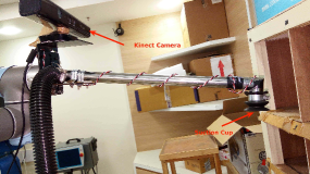
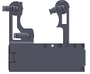
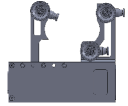
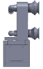
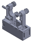
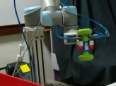
This particular design was employed by the MIT team [66] during the APC 2015 event. In this design, they combined a parallel jaw gripper with a suction system. They also used a compliant spatula to emulate scooping action. In this design, suction was used for picking only very few items which could not be picked by the parallel jaw gripper and hence, a employed single bellow cup capable of picking smaller items. Inspired by this design, we developed a similar hybrid gripper by combining suction cups with a two finger gripper as shown in Figure 16. This gripper was designed to lift a weight of around 2 Kgs. It uses a single actuator with rack pinion mechanism to achieve linear motion between the fingers. The stationary finger houses two bellow cups while the moving finger houses one bellow cup. Hence, it is possible to pick bigger objects through suction by increasing the space between the fingers. The bellow cups are actuated by pneumatic valves that create suction by diverting pressurized air through them. The actual gripper assembly with pneumatic valves and pipes are shown in Figure 17(a) and (b) respectively. The working of the gripper is demonstrated in the experiment section.
IV-G Robot Manipulator Model
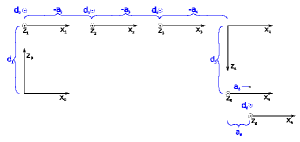
In order to carry out simulation for the actual system, one may need the forward kinematic model of the robot being used. This can be derived using the D-H parameters [67] of the robot. The D-H parameters for UR5 robot [68] is shown in Table I and the corresponding axes for deriving these values are shown in Figure 18. The forward kinematic model thus obtained can be used for solving inverse kinematics of the robot manipulator, developing visual servoing and other motion planning algorithms. In the rest of this section, we describe three popular methods for solving inverse kinematics. The readers are referred to [67] [69] for more detailed treatment on the subject.
 |
 |
| a (m) | d (m) | (rad) | |
|---|---|---|---|
| 0 | 0.0895 | 1.5708 | |
| -0.425 | 0 | 0 | |
| -0.3923 | 0 | 0 | |
| 0 | 0.1092 | 1.5708 | |
| 0 | 0.0947 | -1.5708 | |
| 0 | 0.0823 | 0 |
The forward-kinematic equation is given by the following equation:
| (5) |
Let us assume that and . For a redundant manipulator, . By taking time-derivative on both sides of the above equation, we get
| (6) |
where is the dimensional Jacobian of the manipulator. The joint angles for a given end-effector pose can be obtained using matrix pseudo-inverse as shown below:
| (7) |
where represents the inverse of the Jacobian matrix . If is invertible, the pseudo-inverse is given by the Moore-Penrose inverse equation:
| (8) |
This is otherwise known as the least square solution which minimizes the cost function . The equation (8) is considered as a solution for an over-constrained problem where the number of equations () is less than the number of variables and .
If is invertible, then pseudo-inverse is the minimum norm solution of the least square problem given by the following equation:
| (9) |
The equation (9) is considered to be a solution for an under-constrained problem where the number of equations is less than the number of unknown variables . Note that the equation (9) is also said to provide the right pseudoinverse of as . Note that, and in general, .
IV-G1 Null space optimization
An other property of the pseudoinverse is that the matrix is a projection of onto nullspace. Such that for any vector that satisfies , the joint angle velocities could be written as
| (10) |
In general, for , , and all vectors of the form lie in the null space of , i.e., . By substituting in the above equation, the general inverse kinematic solution may be written as
| (11) |
where is a projector of the joint velocity vector onto . The typical choice of the null space joint velocity vector is
| (12) |
with and is a scalar objective function of the joint variables and represents the gradient of . A number of constraints could be imposed by using this objective function. For instance, the joint limit avoidance can be achieved by selecting the objective function as
| (13) |
where is the middle value of joint angles while () represent maximum (minimum) value of joint angles. The effect of the null space optimizing on joint angle norm is shown in Figure 19(d). As one can see from this figure, the null space optimization for joint limit avoidance leads to a solution with smaller joint angle norm compared to the case when self motion is not used.
IV-G2 Inverse Kinematics as a control problem
The inverse kinematic problem may also be formulated as a closed-loop control problem as described in [70]. Consider the end-effector pose error and its time derivative be give as follows:
| (14) |
By selecting the joint velocities as
| (15) |
the closed loop error dynamics becomes
IV-G3 Damped Least Square Method
The pseudo-inverse method for inverse kinematics is given by
| (16) |
In damped least square method, the is selected so as to minimize the following cost function
| (17) |
This gives us the following expression for joint angle velocities:
| (18) |
The inverse kinematic solutions computed using these conventional methods are shown in Figure 19 20 respectively. Figure 19(a) shows the inverse kinematic solution obtained for a given pose using null space optimization method that avoids joint limits as explained above. The corresponding joint angles are within their physical limits as shown in Figure 19(b). Figure 20 shows the joint configurations for reaching all bin centres of the rack.

V Experimental Results
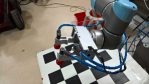
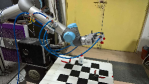
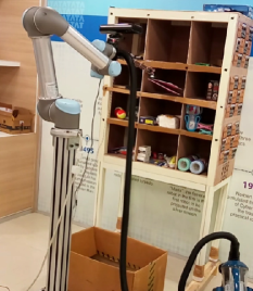
The actual system developed for accomplishing the task of automated picking and stowing is shown in Figure 21. The system comprises of a 6 DOF UR5 robot manipulator with a suction based end-effector, a rack with 12 bins in a grid. The end-effector is powered by a household vacuum cleaner. It uses a Kinect RGBD sensor in an eye-in-hand configuration for carrying out all perception tasks. As explained in Section III, the entire system runs on three laptops connected to each other through ethernet cables. One of these laptops is a Dell Mobile Precision 7710 workstation with a NVIDIA Quadro M5000M GPU process with 8GB of GPU RAM. This laptop is used for running the RCNN network for object detection. The other two laptops have a normal Intel i7 processor with 16 GB of system RAM. The distribution of various nodes on the machines are shown in Figure 3. It is also possible to run the whole system on a single system having necessary CPU and GPU configuration required for the task. The videos showing the operation of the entire system using a suction end-effector [71] [72] and a two-finger gripper [73] is made available on internet for the convenience of the readers. The readers can also use the source codes [74] made publicly available under MIT license for their own use.
V-A Response time
The computation time for different modules of the robotic pick & place system is provided in Table II. As one can see the majority of time is spent in image processing as well as in executing robot motions. Our loop time for picking each object is about 24 seconds which leads to a pick rate of approximately 2.5 objects per minute. The rack detection and system calibration is carried out only once during the whole operation and does not contribute towards the loop time.
| S. No. | Component | Description | Time (seconds) |
|---|---|---|---|
| 1 | Reading JSON file | For ID extraction | 0.01 |
| 2 | Motion 1 | Home position to Bin View Position | 3.5 |
| 3 | Object recognition | using trained RCNN model | 2.32 |
| 4 | Motion 2 | Pre-grasp motion | 9.6 |
| 5 | Motion 3 | Post-grasp motion | 4.97 |
| 6 | Motion 4 | Motion from Tote drop to home position | 3.41 |
| Total loop time for each object | 23.81 | ||
| 7 | Rack Detection | 2.1 | |
| 8 | Calibration | 13.1 | |
V-B Grasping and Suction
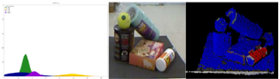
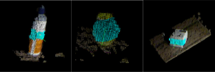
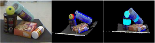
The working of our custom gripper is shown in Figure 22. The maximum clearance between the fingers is about 7 cm and it has been designed to pick up a payload of 2 Kgs. The gripper can grasp things using an antipodal configuration [75] as shown in Figure 22(a). The suction is applied whenever it is not possible to locate grasping affordances on the object. The bellow cups are positioned normal to the surface of the object being picked as shown in Figure 22(b). For grasping, it is necessary to detect the grasp pose and compute the best graspable affordance for a given object. This is done by using the method as described in Section IV-D. Some of the results corresponding to the grasping algorithm is shown in Figure 23. As explained before, a GMM model comprising of color (RGB) information and depth curvature information is effective in segmenting the target object from its background as shown in Figure 23(a) and 23(b) respectively. The outcome of the grasping algorithm is shown in Figure 23(c) and 23(d) respectively. The figure 23(c) shows the best graspable affordance for objects with different shapes while the Figure 23(d) shows the graspable affordance of objects in a clutter.
V-C Object Recognition
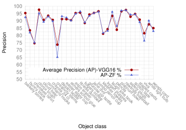
Experiments on object recognition are performed using our APC dataset with 6000 images for 40 different objects. The images are taken at different lighting conditions with various background. Pretrained VGG-16 model of the Faster R-CNN is fine tuned using of the whole dataset and remaining is used to validate the recognition performance. Figure 24 presents some object recognition results when tested with new images. Statistical analysis have been carried out on the validation set. We have achieved a mean Average Precision (mAP) of for our validation set, which is a pretty good performance for such an unconstrained and challenging environment. The individual precision of randomly picked objects and their mAP are shown in Table IV. Observation shows that, when the objects are deformable, such as cherokee tshirt and creativity stems, the precision are reasonably lower. In our case, the precisions are and respectively. The performance can be boosted if the size of the dataset is increased with new set of images. Detailed information of the experimental setup are given in the Table III. GPU system NVIDIA Quadro M5000M is used to train the Faster R-CNN VGG-16 model. Objects in an image are detected in just second, which is in real-time. In order to compare the recognition performance of VGG-16, we trained and validated the given dataset using ZF model. Object recognition results using VGG-16 is observed to be slightly better than that of ZF model (mAP is in case of ZF model). Average precision of individual objects for both the VGG-16 and the ZF model are shown in the Figure 25.
| System | Training | Validation | Testing time | mAP |
| configuration | data size | data size | ||
| GPU NVIDIA | 4800 | 1200 | 0.125 | |
| Quadro M5000M | samples | samples | second |
| mAP | per-class average precision | ||||
|---|---|---|---|---|---|
| barkely bones | bunny book | cherokee tshirt | clorox brush | cloud bear | |
| 89.9 | 95.31 | 83.51 | 74.70 | 97.63 | 90.58 |
| command hooks | crayola 24 ct | creativity stems | dasani bottle | easter sippy cup | |
| 93.52 | 90.57 | 73.65 | 91.21 | 91.13 | |
| elmers school glue | expo eraser | fitness dumbell | folgers coffee | glucose up bottle | |
| 90.36 | 95.27 | 95.64 | 88.45 | 94.34 | |
| jane dvd | jumbo pencil cup | kleenex towels | kygen puppies | laugh joke book | |
| 95.43 | 96.53 | 81.24 | 84.35 | 93.41 | |
| pencils | platinum bowl | rawlings baseball | safety plugs | scotch tape | |
| 83.93 | 96.54 | 97.39 | 92.77 | 94.75 | |
| staples cards | viva | white lightbulb | woods cord | ||
| 90.84 | 81.46 | 87.62 | 85.01 | ||
V-D Direction for future research
While the current system can carry out the picking and stowing tasks with reasonable accuracy and speed, a lot of work still needs to be done before it can be deployed in real world scenarios. Improving the system further forms the direction of our future work. Some of the ways of improving the system is as follows:
-
•
The performance of the system relies on the performance of individual modules, particularly, perception module for object recognition and grasping. One of the future direction would be to carry out research towards improving the performance of the perception module.
-
•
One of the challenges of deep learning based approaches for perception and grasping is the amount of samples required for training such models. Most of these training samples are created manually which is laborious and slow. One of our future direction would be to automate the process of data generation and explore deep learning models that can be trained incrementally [76] or through transfer learning [77][78].
-
•
The design of custom grippers that can pick all types of objects, including soft and deformable objects, still remains a challenge. Picking items from a closely packed stack of objects is another challenge which will be looked into as a part of our future research.
-
•
The real-time performance of the system needs to be improved further without increasing the infrastructure cost. This can be done by parallelizing several modules, improving CPU utilization and reducing network latency. The use of state machine based software architecture [79] such as ROS SMACH [80][81] will be explored as a part of our future work.
-
•
Even though the existing motion planning algorithms are quite mature, it is still not possible to deal with all possible cases of failure. One possible way to deal with these extreme cases would be to have a human in loop that intervenes only when a failure is reported by the system. The human operator can then teach the robot through demonstration [82] [83] to deal with such situations. The robot, in turn, can learn from such human inputs over a period of time to deal with such complex situations through methods such as deep reinforcement learning [84] [85] [86]. Some of these directions will be explored in the future.
-
•
The real-world deployment of such systems will be explored through the use of Cloud Robotics platforms like Rapyuta [87].
VI Conclusions
This paper presents the details of a robot-arm based automatic pick and place system for a retail warehouse. The two major tasks which are considered here include (1) picking items from a rack into a tote and, (2) stowing items from a tote to a rack. These two tasks are currently done manually by employing a large number of people in a big warehouse. This work was carried out as a part of our preparation for participating in the Amazon Picking Challenge 2016 event held in Leipzig, Germany. The problem is challenging from several perspectives. Identifying objects from visual images under conditions of varying illumination, occlusion, scaling, rotation and change of shape (for deformable objects) is an open problem in the computer vision literature. This problem is solved in this work by the use of deep learning networks (RCNN) which gives reasonable accuracy suitable for real world operation. The average recognition accuracy is about for 29 objects which is obtained by training the RCNN network using 4800 training samples. This is quite small compared what was used by other teams at the competition. The lesser accuracy (resulting in bigger bounding boxes for objects) of the recognition module is compensated by the proposed grasping algorithm that uses surface normals, curvatures in the depth space to segment the target object from background, identify its shape and find suitable graspable affordance which could be used for picking the object either using a suction-based end-effector or a two-finger gripper. Apart from these issues, the constraints on real-time performance also pose significant challenge to real-world deployment of such systems. Currently, we are able to achieve a pick or stow rate of 2.5 objects per minute under normal conditions.
References
- [1] Y. Luo, M. Zhou, and R. J. Caudill, “An integrated e-supply chain model for agile and environmentally conscious manufacturing,” IEEE/ASME Transactions On Mechatronics, vol. 6, no. 4, pp. 377–386, 2001.
- [2] Amazon.com, “The largest internet-based retailer in the world.” http://www.amazon.com/.
- [3] S. O’Connor, “Amazon unpacked,” Financial Times, vol. 8, 2013.
- [4] P. J. Reaidy, A. Gunasekaran, and A. Spalanzani, “Bottom-up approach based on internet of things for order fulfillment in a collaborative warehousing environment,” International Journal of Production Economics, vol. 159, pp. 29–40, 2015.
- [5] W. Ding, “Study of smart warehouse management system based on the iot,” in Intelligence Computation and Evolutionary Computation, pp. 203–207, Springer, 2013.
- [6] P. R. Wurman, R. D’Andrea, and M. Mountz, “Coordinating hundreds of cooperative, autonomous vehicles in warehouses,” AI magazine, vol. 29, no. 1, p. 9, 2008.
- [7] N. Mathew, S. L. Smith, and S. L. Waslander, “Planning paths for package delivery in heterogeneous multirobot teams,” IEEE Transactions on Automation Science and Engineering, vol. 12, no. 4, pp. 1298–1308, 2015.
- [8] V. Digani, L. Sabattini, C. Secchi, and C. Fantuzzi, “Ensemble coordination approach in multi-agv systems applied to industrial warehouses,” IEEE Transactions on Automation Science and Engineering, vol. 12, no. 3, pp. 922–934, 2015.
- [9] N. T. Truc and Y.-T. Kim, “Navigation method of the transportation robot using fuzzy line tracking and qr code recognition,” International Journal of Humanoid Robotics, p. 1650027, 2016.
- [10] H.-G. Xu, M. Yang, C.-X. Wang, and R.-Q. Yang, “Magnetic sensing system design for intelligent vehicle guidance,” IEEE/ASME Transactions on Mechatronics, vol. 15, no. 4, pp. 652–656, 2010.
- [11] A. Muis and K. Ohnishi, “Eye-to-hand approach on eye-in-hand configuration within real-time visual servoing,” IEEE/ASME transactions on Mechatronics, vol. 10, no. 4, pp. 404–410, 2005.
- [12] P. R. Wurman and J. M. Romano, “Amazon picking challenge 2015,” AI Magazine, vol. 37, no. 2, pp. 97–99, 2016.
- [13] S. Ren, K. He, R. Girshick, and J. Sun, “Faster r-cnn: Towards real-time object detection with region proposal networks,” in Advances in neural information processing systems, pp. 91–99, 2015.
- [14] C. Hernandez, M. Bharatheesha, W. Ko, H. Gaiser, J. Tan, K. van Deurzen, M. de Vries, B. Van Mil, J. van Egmond, R. Burger, et al., “Team delft’s robot winner of the amazon picking challenge 2016,” arXiv preprint arXiv:1610.05514, 2016.
- [15] Ensenso, “Stereo 3d cameras for industrial applications.” https://www.ensenso.com/.
- [16] M. Quigley, K. Conley, B. Gerkey, J. Faust, T. Foote, J. Leibs, R. Wheeler, and A. Y. Ng, “Ros: an open-source robot operating system,” in ICRA workshop on open source software, vol. 3, p. 5, Kobe, Japan, 2009.
- [17] R. Tsai, “A versatile camera calibration technique for high-accuracy 3d machine vision metrology using off-the-shelf tv cameras and lenses,” IEEE Journal on Robotics and Automation, vol. 3, no. 4, pp. 323–344, 1987.
- [18] Z. Zhang, “A flexible new technique for camera calibration,” IEEE Transactions on pattern analysis and machine intelligence, vol. 22, no. 11, pp. 1330–1334, 2000.
- [19] Z. Zhang, “Microsoft kinect sensor and its effect,” IEEE multimedia, vol. 19, no. 2, pp. 4–10, 2012.
- [20] M. R. Andersen, T. Jensen, P. Lisouski, A. K. Mortensen, M. K. Hansen, T. Gregersen, and P. Ahrendt, “Kinect depth sensor evaluation for computer vision applications,” Technical Report Electronics and Computer Engineering, vol. 1, no. 6, 2015.
- [21] C. L. Lawson and R. J. Hanson, Solving least squares problems, vol. 15. SIAM, 1995.
- [22] K. S. Arun, T. S. Huang, and S. D. Blostein, “Least-squares fitting of two 3-d point sets,” IEEE Transactions on pattern analysis and machine intelligence, no. 5, pp. 698–700, 1987.
- [23] J. Matas, C. Galambos, and J. Kittler, “Robust detection of lines using the progressive probabilistic hough transform,” Comput. Vis. Image Underst., vol. 78, pp. 119–137, Apr. 2000.
- [24] G. Bradski et al., “The opencv library,” Doctor Dobbs Journal, vol. 25, no. 11, pp. 120–126, 2000.
- [25] A. K. Jain, N. K. Ratha, and S. Lakshmanan, “Object detection using gabor filters,” Pattern recognition, vol. 30, no. 2, pp. 295–309, 1997.
- [26] S. Belongie, J. Malik, and J. Puzicha, “Shape matching and object recognition using shape contexts,” IEEE transactions on pattern analysis and machine intelligence, vol. 24, no. 4, pp. 509–522, 2002.
- [27] D. G. Lowe, “Distinctive image features from scale-invariant keypoints,” International journal of computer vision, vol. 60, no. 2, pp. 91–110, 2004.
- [28] N. Dalal and B. Triggs, “Histograms of oriented gradients for human detection,” in Computer Vision and Pattern Recognition, 2005. CVPR 2005. IEEE Computer Society Conference on, vol. 1, pp. 886–893, IEEE, 2005.
- [29] R. Girshick, J. Donahue, T. Darrell, and J. Malik, “Region-based convolutional networks for accurate object detection and segmentation,” IEEE transactions on pattern analysis and machine intelligence, vol. 38, no. 1, pp. 142–158, 2016.
- [30] Y. Zhang, K. Sohn, R. Villegas, G. Pan, and H. Lee, “Improving object detection with deep convolutional networks via bayesian optimization and structured prediction,” in Proceedings of the IEEE Conference on Computer Vision and Pattern Recognition, pp. 249–258, 2015.
- [31] W. Liu, D. Anguelov, D. Erhan, C. Szegedy, S. Reed, C.-Y. Fu, and A. C. Berg, “Ssd: Single shot multibox detector,” in European Conference on Computer Vision, pp. 21–37, Springer, 2016.
- [32] P. Felzenszwalb, D. McAllester, and D. Ramanan, “A discriminatively trained, multiscale, deformable part model,” in IEEE Conference on Computer Vision and Pattern Recognition, 2008. CVPR 2008., pp. 1–8, IEEE, 2008.
- [33] R. Girshick, J. Donahue, T. Darrell, and J. Malik, “Rich feature hierarchies for accurate object detection and semantic segmentation,” in Proceedings of the IEEE conference on computer vision and pattern recognition, pp. 580–587, 2014.
- [34] R. Girshick, “Fast r-cnn,” in Proceedings of the IEEE International Conference on Computer Vision, pp. 1440–1448, 2015.
- [35] J. Redmon, S. Divvala, R. Girshick, and A. Farhadi, “You only look once: Unified, real-time object detection,” in Proceedings of the IEEE Conference on Computer Vision and Pattern Recognition, pp. 779–788, 2016.
- [36] B. Kehoe, A. Matsukawa, S. Candido, J. Kuffner, and K. Goldberg, “Cloud-based robot grasping with the google object recognition engine,” in Robotics and Automation (ICRA), 2013 IEEE International Conference on, pp. 4263–4270, IEEE, 2013.
- [37] D. Fischinger, M. Vincze, and Y. Jiang, “Learning grasps for unknown objects in cluttered scenes,” in Robotics and Automation (ICRA), 2013 IEEE International Conference on, pp. 609–616, IEEE, 2013.
- [38] A. Saxena, J. Driemeyer, and A. Y. Ng, “Robotic grasping of novel objects using vision,” The International Journal of Robotics Research, vol. 27, no. 2, pp. 157–173, 2008.
- [39] M. Gualtieri, A. ten Pas, K. Saenko, and R. Platt, “High precision grasp pose detection in dense clutter,” in Intelligent Robots and Systems (IROS), 2016 IEEE/RSJ International Conference on, pp. 598–605, IEEE, 2016.
- [40] J. Redmon and A. Angelova, “Real-time grasp detection using convolutional neural networks,” in Robotics and Automation (ICRA), 2015 IEEE International Conference on, pp. 1316–1322, IEEE, 2015.
- [41] I. Lenz, H. Lee, and A. Saxena, “Deep learning for detecting robotic grasps,” The International Journal of Robotics Research, vol. 34, no. 4-5, pp. 705–724, 2015.
- [42] G. P. Otto and T. K. Chau, “‘region-growing’algorithm for matching of terrain images,” Image and vision computing, vol. 7, no. 2, pp. 83–94, 1989.
- [43] R. Schnabel, R. Wahl, and R. Klein, “Efficient ransac for point-cloud shape detection,” in Computer graphics forum, vol. 26, pp. 214–226, Wiley Online Library, 2007.
- [44] N. J. Mitra and A. Nguyen, “Estimating surface normals in noisy point cloud data,” in Proceedings of the nineteenth annual symposium on Computational geometry, pp. 322–328, ACM, 2003.
- [45] P. Kovesi, “Shapelets correlated with surface normals produce surfaces,” in Computer Vision, 2005. ICCV 2005. Tenth IEEE International Conference on, vol. 2, pp. 994–1001, IEEE, 2005.
- [46] T. Rabbani, F. Van Den Heuvel, and G. Vosselmann, “Segmentation of point clouds using smoothness constraint,” International archives of photogrammetry, remote sensing and spatial information sciences, vol. 36, no. 5, pp. 248–253, 2006.
- [47] Z. Zivkovic, “Improved adaptive gaussian mixture model for background subtraction,” in Pattern Recognition, 2004. ICPR 2004. Proceedings of the 17th International Conference on, vol. 2, pp. 28–31, IEEE, 2004.
- [48] B. Siciliano, L. Sciavicco, L. Villani, and G. Oriolo, Robotics: modelling, planning and control. Springer Science & Business Media, 2010.
- [49] D. E. Koditschek, “Robot planning and control via potential functions,” The robotics review, p. 349, 1989.
- [50] J. Barraquand, B. Langlois, and J.-C. Latombe, “Numerical potential field techniques for robot path planning,” IEEE Transactions on Systems, Man, and Cybernetics, vol. 22, no. 2, pp. 224–241, 1992.
- [51] Y. K. Hwang and N. Ahuja, “A potential field approach to path planning,” IEEE Transactions on Robotics and Automation, vol. 8, no. 1, pp. 23–32, 1992.
- [52] N. Malone, A. Faust, B. Rohrer, R. Lumia, J. Wood, and L. Tapia, “Efficient motion-based task learning for a serial link manipulator,” Transaction on Control and Mechanical Systems, vol. 3, no. 1, 2014.
- [53] L. E. Kavraki, P. Svestka, J.-C. Latombe, and M. H. Overmars, “Probabilistic roadmaps for path planning in high-dimensional configuration spaces,” IEEE transactions on Robotics and Automation, vol. 12, no. 4, pp. 566–580, 1996.
- [54] F. Avnaim, J.-D. Boissonnat, and B. Faverjon, “A practical exact motion planning algorithm for polygonal objects amidst polygonal obstacles,” in Robotics and Automation, 1988. Proceedings., 1988 IEEE International Conference on, pp. 1656–1661, IEEE, 1988.
- [55] F. Lingelbach, “Path planning using probabilistic cell decomposition,” in Robotics and Automation, 2004. Proceedings. ICRA’04. 2004 IEEE International Conference on, vol. 1, pp. 467–472, IEEE, 2004.
- [56] S. M. LaValle and J. J. Kuffner Jr, “Rapidly-exploring random trees: Progress and prospects,” 2000.
- [57] I. A. Sucan, M. Moll, and L. E. Kavraki, “The open motion planning library,” IEEE Robotics & Automation Magazine, vol. 19, no. 4, pp. 72–82, 2012.
- [58] MoveIt!, “Open-source software for manipulation.” http://moveit.ros.org/.
- [59] J. Rosell, A. Pérez, A. Aliakbar, L. Palomo, N. García, et al., “The kautham project: A teaching and research tool for robot motion planning,” in Proceedings of the 2014 IEEE Emerging Technology and Factory Automation (ETFA), pp. 1–8, IEEE, 2014.
- [60] R. Diankov and J. Kuffner, “Openrave: A planning architecture for autonomous robotics,” Robotics Institute, Pittsburgh, PA, Tech. Rep. CMU-RI-TR-08-34, vol. 79, 2008.
- [61] D. Roberts, R. Wolff, O. Otto, and A. Steed, “Constructing a gazebo: supporting teamwork in a tightly coupled, distributed task in virtual reality,” Presence, vol. 12, no. 6, pp. 644–657, 2003.
- [62] J. Pan, S. Chitta, and D. Manocha, “Fcl: A general purpose library for collision and proximity queries,” in Robotics and Automation (ICRA), 2012 IEEE International Conference on, pp. 3859–3866, IEEE, 2012.
- [63] K. M. Wurm, A. Hornung, M. Bennewitz, C. Stachniss, and W. Burgard, “Octomap: A probabilistic, flexible, and compact 3d map representation for robotic systems,” in Proc. of the ICRA 2010 workshop on best practice in 3D perception and modeling for mobile manipulation, vol. 2, 2010.
- [64] C. Rennie, R. Shome, K. E. Bekris, and A. F. De Souza, “A dataset for improved rgbd-based object detection and pose estimation for warehouse pick-and-place,” IEEE Robotics and Automation Letters, vol. 1, no. 2, pp. 1179–1185, 2016.
- [65] C. Eppner, S. Höfer, R. Jonschkowski, R. Martın-Martın, A. Sieverling, V. Wall, and O. Brock, “Lessons from the amazon picking challenge: Four aspects of building robotic systems,” 2016.
- [66] K.-T. Yu, N. Fazeli, N. Chavan-Dafle, O. Taylor, E. Donlon, G. D. Lankenau, and A. Rodriguez, “A summary of team mit’s approach to the amazon picking challenge 2015,” arXiv preprint arXiv:1604.03639, 2016.
- [67] J. J. Craig, Introduction to robotics: mechanics and control, vol. 3. Pearson Prentice Hall Upper Saddle River, 2005.
- [68] Universal Robots Support, “Axes for computing d-h parameter of an ur5 robot.” https://www.universal-robots.com/how-tos-and-faqs/faq/ur-faq/actual-center-of-mass-for-robot-17264/.
- [69] M. W. Spong and M. Vidyasagar, “Robot dynamics and control, 1989,” and, vol. 247251, p. 141150, 1991.
- [70] J. Wang, Y. Li, and X. Zhao, “Inverse kinematics and control of a 7-dof redundant manipulator based on the closed-loop algorithm,” International Journal of Advanced Robotic Systems, vol. 7, no. 4, pp. 1–9, 2010.
- [71] S. Jotawar, “An automated robotic pick and place system for a retail warehouse.” https://www.youtube.com/watch?v=jQ4_poYAXZU, 2016.
- [72] L. Behera, “IITK-TCS participation in amazon picking challenge 2016.” https://sites.google.com/site/swagatkumar/home/apc_iitk_tcs, 2016.
- [73] M. Soni and O. Kundu, “Demonstration of grasping algorithm.” https://www.youtube.com/watch?v=lCxMGvCKe_g, 2016.
- [74] N. Kejriwal and S. Jotawar, “Software codes developed by iitk-tcs team for amazon picking challenge 2016.” https://github.com/amazon-picking-challenge/team_iitk_tcs, 2016.
- [75] A. t. Pas and R. Platt, “Using geometry to detect grasps in 3d point clouds,” arXiv preprint arXiv:1501.03100, 2015.
- [76] T. Xiao, J. Zhang, K. Yang, Y. Peng, and Z. Zhang, “Error-driven incremental learning in deep convolutional neural network for large-scale image classification,” in Proceedings of the 22nd ACM international conference on Multimedia, pp. 177–186, ACM, 2014.
- [77] H.-C. Shin, H. R. Roth, M. Gao, L. Lu, Z. Xu, I. Nogues, J. Yao, D. Mollura, and R. M. Summers, “Deep convolutional neural networks for computer-aided detection: Cnn architectures, dataset characteristics and transfer learning,” IEEE transactions on medical imaging, vol. 35, no. 5, pp. 1285–1298, 2016.
- [78] J. Yosinski, J. Clune, Y. Bengio, and H. Lipson, “How transferable are features in deep neural networks?,” in Advances in neural information processing systems, pp. 3320–3328, 2014.
- [79] H. Herrero, J. L. Outón, U. Esnaola, D. Sallé, and K. L. de Ipiña, “State machine based architecture to increase flexibility of dual-arm robot programming,” in International Work-Conference on the Interplay Between Natural and Artificial Computation, pp. 98–106, Springer, 2015.
- [80] J. Bohren and S. Cousins, “The smach high-level executive [ros news],” IEEE Robotics & Automation Magazine, vol. 17, no. 4, pp. 18–20, 2010.
- [81] T. Field, “Smach documentation,” Online at http://www. ros. org/wiki/smach/Documentation, 2011.
- [82] S. Calinon and A. Billard, “Active teaching in robot programming by demonstration,” in Robot and Human interactive Communication, 2007. RO-MAN 2007. The 16th IEEE International Symposium on, pp. 702–707, IEEE, 2007.
- [83] Y. Maeda, N. Ishido, H. Kikuchi, and T. Arai, “Teaching of grasp/graspless manipulation for industrial robots by human demonstration,” in Intelligent Robots and Systems, 2002. IEEE/RSJ International Conference on, vol. 2, pp. 1523–1528, IEEE, 2002.
- [84] T. P. Lillicrap, J. J. Hunt, A. Pritzel, N. Heess, T. Erez, Y. Tassa, D. Silver, and D. Wierstra, “Continuous control with deep reinforcement learning,” arXiv preprint arXiv:1509.02971, 2015.
- [85] S. Levine, P. Pastor, A. Krizhevsky, and D. Quillen, “Learning hand-eye coordination for robotic grasping with deep learning and large-scale data collection,” arXiv preprint arXiv:1603.02199, 2016.
- [86] F. Zhang, J. Leitner, M. Milford, B. Upcroft, and P. Corke, “Towards vision-based deep reinforcement learning for robotic motion control,” arXiv preprint arXiv:1511.03791, 2015.
- [87] G. Mohanarajah, D. Hunziker, R. D’Andrea, and M. Waibel, “Rapyuta: A cloud robotics platform,” IEEE Transactions on Automation Science and Engineering, vol. 12, no. 2, pp. 481–493, 2015.