Successive field-induced transitions in BiFeO3 around room temperature
Abstract
The effects of high magnetic fields applied perpendicular to the spontaneous ferroelectric polarization on single crystals of BiFeO3 were investigated through magnetization, magnetostriction, and neutron diffraction measurements. The magnetostriction measurements revealed lattice distortion of , during the reorientation process of the cycloidal spin order by applied magnetic fields. Furthermore, anomalous changes in magnetostriction and electric polarization at a larger field demonstrate an intermediate phase between cycloidal and canted antiferromagnetic states, where a large magnetoelectric effect was observed. Neutron diffraction measurements clarified that incommensurate spin modulation along [110] direction in the cycloidal phase becomes commensurate in the intermediate phase. Theoretical calculations based on the standard spin Hamiltonian of this material suggest an antiferromagnetic cone-type spin order in the intermediate phase.
Recently, multiferroic materials have been widely investigated due to their coupling between magnetic and ferroelectric ordering. BiFeO3 is perhaps the most extensively studied multiferroic material as it possesses robust multiferroicity at room temperature as well as various possible applications kezmarki2015 ; chu2008 ; choi2009 ; wu2010 ; jiang2011 ; wang2011 ; tsurumaki2012 ; hong2013 ; kawachi2016 ; yang2009 . The effects of magnetic fields on the coupled multiple degrees of freedom behind these phenomena are not fully understood.
BiFeO3 exhibits a cycloidal magnetic order below 640 K sosnovska1982 . This state is known to exhibit marginal quadratic magnetoelectric (ME) effect at low magnetic fields munoz1985 . High magnetic fields of 20 T stabilize the canted antiferromagnetic (CAFM) phase as opposed to the cycloidal phase popov1993 ; kadomtseva1995 ; ruette2004 ; tokunaga2015jmmm ; tokunaga2015 . Although several groups succeeded in realizing the CAFM phase at zero field chen2012 ; Sosnowska2013 ; yamamoto2016 ; bai2005 ; bea2005 ; Sando2013 , the ME effect in this phase has not been clarified. In this study, several features were observed when a magnetic field was applied normal to the trigonal -axis, and they indicated that a third magnetic phase emerged in bulk BiFeO3 between the cycloidal and CAFM phases at approximately room temperature.
BiFeO3 has a crystal structure with the polar space group of . A large switchable spontaneous electric polarization emerges along the -axis of the trigonal cell Shvartsman2007 ; Lebeugle2007 ; Catalan2009 . Degeneracy exists in selecting the polarization direction from eight directions in the cubic unit. Hence, depending on synthesis methods, BiFeO3 crystals can contain multiple ferroelectric domains slee2008prb .
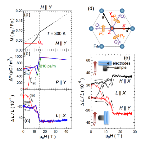
Magnetic domains can be present even in single ferroelectric domain crystals. The magnetic propagation vector points in one of the directions of the trigonal cell sosnovska1982 in the cycloidal spin ordered state below 640 K. The three-fold rotational symmetry around the -axis ( direction in this paper) leads to three equivalent , as shown in Fig. 1(d). The spins rotated primarily in the - plane in a magnetic domain with a given .
Recently, Tokunaga . indicated the emergence of an electric polarization perpendicular to the direction that was controlled by magnetic fields tokunaga2015 . Theoretical calculations suggested that the cycloidal spin order in BiFeO3 could involve electric polarization perpendicular to the - plane as illustrated as in Fig. 1(d) lee2015 ; miyahara2016 ; kaplan2011 . The existence of indicated that three-fold rotational symmetry was broken in the cycloidal state. Therefore, BiFeO3 had lower symmetry than at room temperature. Sosnowska . examined the crystal structure of BiFeO3 using synchrotron X-ray diffraction and proposed that monoclinic distortion led to the observed broadening of the Bragg peaks below 1038 K sosnowska2012 . However, relation between the magnetic order and the monoclinic distortion was not clear since this broadening was observed even at temperatures well above 640 K.
In this study, the magnetization and magnetostriction of single ferroelectric domain crystals of BiFeO3 synthesized by the laser-diode heating floating-zone method Ito2011 were measured in pulsed high magnetic fields at ISSP. The magnetization were measured by the induction method. Newly improved capacitance dilatometry enabled the measurement of magnetostriction using the capacitance method kido1989 . The neutron diffraction experiments were carried out on the BT-7 thermal neutron triple-axis spectrometer at the NIST Center for Neutron Research bt7 . The magnetic domains of the crystal were previously aligned by applying magnetic field along the direction [see Fig. 1(d)]. The single crystal was oriented
in the () or () scattering plane and was mounted in a 15 T vertical field superconducting magnet. The magnetic field was applied along direction. Details of the neutron experiment are described in the supplementary material supplementary .
Figure 1(a) shows the magnetization () curve at 300 K in the magnetic field () applied along the direction. The kink at 15 T indicated the existence of a magnetic transition at this field tokunaga2015 . Extrapolation of the linear - curve at high field to zero field indicated finite offsets in the vertical axis and thus suggested that the high field phase possesses spontaneous magnetization (). Figure 1(b) presents the change in electric polarization along the direction () caused by a magnetic field . The steeply changes below 10 T in the field increasing process of the first field cycle (red). However, this change was suppressed in the second field cycle (blue). This irreversible change (also known as the non-volatile effect) was ascribed to the reorientation of the magnetoelectric domains kawachi2016 ; tokunaga2015 . It was assumed that the transverse electric polarization changed the direction during the reorientation of the cycloidal domains to the domain in the initial field scan.
The emergence of indicates that three-fold
rotational symmetry was broken at 300 K. We measured the transverse magnetostriction with at 300 K to detect the relevant lattice distortion. The vertical axis in Fig. 1(c) corresponds to the field-induced change in the sample length along () normalized by the length at zero field (). The field dependence of followed that of , in the opposite sign, including the irreversible behavior below 10 T. This measurement demonstrated that the application of a temporal magnetic field slightly compressed the crystal normal to the - plane. Prior to this experiment, we measured the magnetostriction along the direction for while maintaining the capacitance cell set-up [insets of Fig. 1(e)]. This result is indicated by a black solid line in Fig. 1(e). In the case of , the crystal length along the direction increased. The initial position of the for was the same as its final position after the application of . Therefore, the data for is plotted with the vertical offset of . These irreversible behaviors below 10 T indicated that the sample length changed due
to the direction of . A neutron experiment in a recent study confirmed that application of of 6 T would stabilize the domain in Fig. 1(d) matsuda_unpub . Contraction of the sample along the direction for indicated that the sample slightly contracted along the vector. This result is consistent with the early report of neutron diffraction measurements showing that the population of the magnetic domain with the vector normal to the applied pressure direction decreased when uniaxial pressure was applied along the principal axis of the pseudocubic unit cell Ramazanoglu2011 .
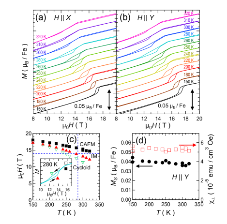
A systematic analysis of the data obtained after the domain reorientation in Figs. 1(a)-(c) indicated that all the quantities showed non-monotonic changes between 10 T and 15 T. In order to clarify this anomaly, we measured the magnetization with and at various temperatures. The results are shown in Figs. 2(a) and 2(b). As observed in these figures, no intrinsic differences were detected in the - curves for and . At 150 K, the magnetization showed a step-like change at the transition field. Conversely, - curves above 200 K showed the region with a large gradient in the intermediate field region. In the following, we will refer to the magnetic phase in this intermediate region as the IM phase. The transition from the cycloidal phase to the IM phase was discontinuous while that from the IM phase to the CAFM phase was continuous. The IM phase appeared from the lower field as the temperature increased. Figure 2(c) shows the phase diagram in the - plane determined by the magnetization curves. Here, characteristic fields were assigned in the magnetization curves as the transition fields as marked by several symbols in the inset of Fig. 2(c).
Gareeva . theoretically predicted the emergence of the intermediate phase gareeva2013 . Their study proposed that an antiferromagnetic cone (AF-cone) phase existed between the cycloidal and CAFM phases in the magnetic fields parallel as well as perpendicular to the trigonal axis. The calculations suggested that the boundary between the cycloidal and AF-cone phases corresponded to a first order phase transition, and this is consistent with the results of the present study. Their calculations focused on a one-dimensional spatially modulated spin structure along a fixed direction. Therefore, it is necessary to consider more general states in order to determine the actual spin order in the IM phase.
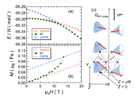
We performed calculations starting with the following spin Hamiltonian Jeong2012 ; Matsuda2012 ; Fishman2012 :
Here, , and , , represent the Fe sites and three adjacent directions in the pseudocubic cell as shown in Fig. 3(c), respectively. and represent nearest and next-nearest neighbor interaction. , , and denote DM interactions and single-ion anisotropy. Figure 3(a) shows the energy of several phases as a function of magnetic field applied normal to the direction with typical values of parameters parameters . An intermediate (IM) phase is stabilized between the cycloidal and CAFM phases. The IM phase shows an AF cone-type spin structure with the propagation vector pointing to the field direction as shown in Fig. 3(c). In the present Hamiltonian, the terms stabilize the cycloidal state, while the term favors the CAFM one. The AF cone state is a kind of the superposition of these two orders caused by the competition of these two DM interactions. Figure 3(b) shows calculated magnetization curves for the three phases. The gradual increase in magnetization for the IM phase reproduces the experimentally observed change in the slope shown in Fig. 2(b).
In this AF-cone state, spin susceptibility along the spin modulation vector will be larger than that normal to it. Accordingly, a flop of the modulation vector can be
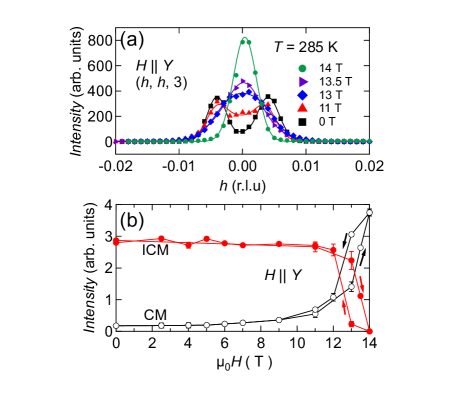
caused by the transition from the cycloidal to the AF-cone state. Therefore, we performed neutron diffraction measurements of BiFeO3 to study the field dependence of the spin modulation through this transition. We performed scans along the direction at 285 K under applied . The data were taken as we ramped up the magnetic field and these scans are shown in Figure 4(a). As the field increases, the incommensurate peaks at 0.004 are reduced in intensity, while in contrast, the commensurate peak at = 0 grows. In Fig. 4(b), we show the field dependence of the integrated intensities of the commensurate and incommensurate peaks. At 285 K, application of 14 T was sufficient to reach the IM phase, but insufficient to reach the CAFM phase, at this temperature as denoted by a cross point of vertical and horizontal dashed lines in Fig. 2(c). An increase in magnetic fields from 6 T led to a gradual increase and decrease in the commensurate and incommensurate scattering intensities, respectively. The spin structure appeared commensurate along the direction in the IM phase realized at 14 T. By using the results of the present study, it is not possible to conclude whether the spin structure was commensurate or incommensurate along the direction due to the limited resolution out of the scattering plane. A decrease in the magnetic field resulted in the change from the commensurate state to the incommensurate state showing hysteresis. The coexistence of commensurate/incommensurate scattering supports the conclusion that the transition from the cycloidal phase to the IM phase is first order. The disappearance of the incommensurate spin modulation along the direction in the IM phase did not contradict the picture of the AF-cone phase as shown in Fig. 3(c). We also performed neutron diffraction measurements with and found that the transition to the IM phase occurred at 14 T supplementary , consistent with the magnetization results.
In the IM phase, magnetization, electric polarization, and magnetostriction changed linearly as a function of magnetic field. The coefficient of the linear ME effect between 12 T and 15 T shown in Fig. 1(b) is approximately 210 ps/m. Although we cannot identify this value determined in a limited field region as the representative one in the IM phase, the observed large ME effect implies the presence of strong ME coupling in this phase.
Thus far, we have not succeeded in reproducing the ME effect in the IM phase based on the generalized inverse Dzyaloshinskii-Moriya effect miyahara2016 . Phenomenologically, the ME effect might be explained by slight tilting of the trigonal -axis by the monoclinic distortion. Using the reported lattice parameters sosnowska2012 , we determined that the tilting angle was supplementary . Assuming a spontaneous polarization of 1Cm2 along the -axis, the projected component will be between 200 and 800 Cm2, which is the same order of magnitude with the observed transverse component. The important point here is that the tilting is coupled to the spin system, and hence, can be controlled by an external magnetic field.
Finally, the study involved examining ways to realize the IM phase at lower magnetic fields than the fields observed in this study. In accordance with the Landau-Ginzburg theory for BiFeO3, exchange stiffness, DM interaction, magnetic anisotropy constant (), differential magnetic susceptibility (), and spontaneous magnetization in the CAFM phase () are fundamental parameters. Among these parameters, and were determined from the experimental results of the - curves. Figure 2(d) shows the temperature dependence of these parameters determined from the magnetization curves at various temperatures. These parameters were almost constant at temperatures from 150 K to 320 K. The temperature dependence of the transition field to the IM phase could be a result of the change in because the exchange stiffness and DM interaction are likely insensitive to temperature. Such temperature dependence of may appear as the change in anharmonicity in the cycloidal order, which is observed experimentally Ramazanoglu2011b . According to a theoretical study gareeva2013 , when was increased, while holding the other parameters constant, the transition field to the AF-cone phase was reduced. Therefore, future research could examine the AF-cone phase in thin films with large .
In summary, magnetization, magnetostriction, and neutron diffraction measurements were performed on single BiFeO3 crystals in magnetic fields applied normal to the trigonal axis. The observations indicated that the reorientation of multiferroic domains occurred below 10 T in conjunction with irreversible field-induced change in the lattice distortion. This demonstrated the existence of a monoclinic distortion in the cycloidal phase. The application of an increased magnetic field realized an intermediate phase prior to the transition to the canted antiferromagnetic state. A large ME effect was observed in this intermediate phase. Theoretical calculations indicated the presence of an antiferromagnetic cone-type spin order in this phase, consistent with the neutron diffraction measurements.
This work was supported by the MEXT of Japan Grant-in-Aid for Challenging Exploratory Research (16K05413), and Murata Science Foundation.
References
- (1) I. Kézsmárki, U. Nagel, S. Bordacs, R. S. Fishman, J. H. Lee, Hee Taek Yi, S.-W. Cheong, and T. Rõõm, Phys. Rev. Lett. 115, 127203 (2015).
- (2) Y.-H. Chu, L.W. Martin, M. B. Holcomb, M. Gajek, S.-J. Han, Q. He, N. Balke, C.-H. Yang, D. Lee, W. Hu, Q. Zhan, P.-L. Yang, A. F.-Rodríguez, A. Scholl, S. X. Wang, and R. Ramesh, Nat. Mater. 7, 478 (2008).
- (3) T. Choi, S. Lee, Y. J. Choi, V. Kiryukhin, and S. -W. Cheong, Science 324, 63 (2009).
- (4) S. M. Wu, Shane A. Cybart, P. Yu, M. D. Rossell, J. X. Zhang, R. Ramesh, and R. C. Dynes, Nat. Mater. 9, 756 (2010).
- (5) A. Q. Jiang, C. Wang, K. J. Jin, X. B. Liu, J. F. Scott, C. S. Hwang, T. A. Tang, H. B. Lu, and G. Z. Yang, Adv. Mater. 23, 1277 (2011).
- (6) C. Wang, K.-j. Jin, Z.-t. Xu, L. Wang, C. Ge, H.-b. Lu, H.-z. Guo, M. He, and G.-z. Yang, Appl. Phys. Lett. 98, 192901 (2011).
- (7) A. Tsurumaki, H. Yamada, and A. Sawa, Adv. Funct. Mater. 22, 1040 (2012).
- (8) S. Hong, T. Choi, J. H. Jeon, Y. Kim, H. Lee, H.-Y. Joo, I. Hwang, J.-S. Kim, S.-O. Kang, S. V. Kalinin, and B. H. Park, Adv. Mater. 25, 2339 (2013).
- (9) S. Kawachi, H. Kuroe, T. Ito, A. Miyake, and M. Tokunaga, Appl. Phys. Lett. 108, 162903 (2016).
- (10) S. Y. Yang, L. W. Martin, S. J. Byrnes, T. E. Conry, S. R. Basu, D. Paran, L. Reichertz, J. Ihlefeld, C. Adamo, A. Melville, Y.-H. Chu, C.-H. Yang, J. L. Musfeldt, D. G. Schlom, J. W. Ager III and R. Ramesh, Appl. Phys. Lett. 95, 062909 (2009).
- (11) I. Sosnowska, T. Peterlin-Neumaier, and E. Steichele, J. Phys. C 15, 4835 (1982).
- (12) C. Tabares-Muoz, J. -P. Rivera, A. Bezinges, A. Monnier, and H. Schmid, Japan. J. Appl. Phys. , 1051 (1985).
- (13) Y. F. Popov, A. K. Zvezdin, G. P. Vorob’ev, A. M. Kadomtseva, V. A. Murashev, and D. N. Racov, JETP Lett. 57, 69 (1993).
- (14) A. M. Kadomtseva, Y. F. Popov, G. P. Vorob’ev, and A. K. Zvezdin, Phys. B 211, 327 (1995).
- (15) B. Ruette, S. Zvyagin, A. P. Pyatakov, A. Bush, J. F. Li, V. I. Belotelov, A. K. Zvezdin, and D. Viehland, Phys. Rev. B 69, 064114 (2004).
- (16) M. Tokunaga, M. Akaki, A. Miyake, T. Ito, and H. Kuwahara, J. Magn. Magn. Mater. 383, 259 (2015).
- (17) M. Tokunaga, M. Akaki, T. Ito, S. Miyahara, A. Miyake, H. Kuwahara, and N. Furukawa, Nat. Commun. 6, 5878 (2015).
- (18) P. Chen, . Gnaydin-en, W. J. Ren, Z. Qin, T. V. Brinzari, S. McGill, S.-W. Cheong, and J. L. Musfeldt, Phys. Rev. B , 014407 (2012).
- (19) I. Sosnowska, M. Azuma, R. Przenioso, D. Wardecki, W.-t. Chen, K. Oka, and Y. Shimakawa, Inorg. Chem. , 13269 (2013).
- (20) H. Yamamoto, T. Kihara, K. Oka, M. Tokunaga, K. Mibu, and M. Azuma, J. Phys. Soc. Jpn. 85, 064704 (2016).
- (21) F. Bai, J. Wang, M. Wuttig, J. Li, N. Wang, A. P. Pyatakov, A. K. Zvezdin, L. E. Cross, and D. Viehland, Appl. Phys. Lett. , 032511 (2005).
- (22) H. Ba, M. Bibes, A. Barthlmy, K. Bouzehouane, E. Jacquet, A. Khodan, J.-P. Contour, S. Fusil, F. Wyczisk, A. Forget, D. Lebeugle, D. Colson, and M. Viret, Appl. Phys. Lett. , 072508 (2005).
- (23) D. Sando, A. Agbelele, D. Rahmedov, J. Liu, P. Rovillain, C. Toulouse, I. C. Infante, A. P. Pyatakov, S. Fusil, E. Jacquet, C. Carretero, C. Deranlot, S. Lisenkov, D. Wang, J-M. Le Breton, M. Cazayous, A. Sacuto, J. Juraszek, A. K. Zvezdin, L. Bellaiche, B. Dkhil, A. Barthelemy, and M. Bibes, Nat. Mater. 12, 641 (2013).
- (24) V. V. Shvartsman, W. Kleemann, R. Haumont, and J. Kreisel, Appl. Phys. Lett. 90, 172115 (2007).
- (25) D. Lebeugle, D. Colson, A. Forget, M. Viret, P. Bonville, J. F. Marucco, and S. Fusil, Phys. Rev. B 76, 024116 (2007).
- (26) G. Catalan and J. F. Scott Adv. Mater. 21, 2463 (2009).
- (27) S. Lee, T. Choi, W. Ratcliff, R. Erwin, S-W. Cheong, V. Kiryukhin, Phys. Rev. B 78, 100101(R) (2008).
- (28) J. H. Lee and R. S. Fishman, Phys. Rev. Lett. 115, 207203 (2015).
- (29) S. Miyahara and N. Furukawa, Phys. Rev. B 93, 014445 (2016).
- (30) T. A. Kaplan and S. D. Mahanti, Phys. Rev. B 83, 174432 (2011).
- (31) I. Sosnowska, R. Przenioslo, A. Palewicz, D. Wardecki, and A. Fitch, J. Phys. Soc. Jpn. 81, 044604 (2012).
- (32) T. Ito, T. Ushiyama, Y. Yanagisawa, R. Kumai, and Y. Tomioka, Cryst. Growth Des. 11, 5139 (2011).
- (33) G. Kido, Physica B 155, 199 (1989).
- (34) J. W. Lynn, Y. Chen, S. Chang, Y. Zhao, S. Chi, W. Ratcliff, II, B. G. Ueland, and R. W. Erwin, Journal of Research of NIST 117, 61 (2012).
- (35) See supplementary material at http://dx.doi.org/xxx for the neutron experimental details and estimation of the transverse polarization caused by the tilting of the trigonal -axis.
- (36) S. E. Dissanayake, T. Hong, T. Ito, and M. Matsuda, (unpublished).
- (37) M. Ramazanoglu, W. Ratcliff, II, H. T. Yi, A. A. Sirenko, S.-W. Cheong, and V. Kiryukhin, Phys. Rev. Lett. 107, 067203 (2011).
- (38) Z. V. Gareeva, A. F. Popkov, S. V. Soloviov, and A. K. Zvezdin, Phys. Rev. B 87, 214413 (2013).
- (39) J. Jeong, E. A. Goremychkin, T. Guidi, K. Nakajima, G. S. Jeon, S.-A. Kim, S. Furukawa, Y. B. Kim, S. Lee, V. Kiryukhin, S.-W. Cheong, and J.-G. Park, Phys. Rev. Lett. 108, 077202 (2012).
- (40) M. Matsuda, R. S. Fishman, T. Hong, C. H. Lee, T. Ushiyama, Y. Yanagisawa, Y. Tomioka, and T. Ito, Phys. Rev. Lett. 109, 067205 (2012).
- (41) R. S. Fishman, J. T. Haraldsen, N. Furukawa, and S. Miyahara, Phys. Rev. B 87, 134416 (2013).
- (42) We used S = 5/2, J1 = 5.32 meV, J2 = 0.24 meV, D = - 0.15 meV, D′ = 0.1 meV, K = 0.0055 meV, and g =2, which are slightly tuned from the values in Jeong2012 ; Matsuda2012 ; Fishman2012 .
- (43) M. Ramazanoglu, W. Ratcliff, II, Y. J. Choi, Seongsu Lee, S. -W. Cheong, and V. Kiryukhin, Phys. Rev. B 83, 174434 (2011).