The Construction of the Fiber-SiPM beam monitor system of the R484 and R582 Experiments at the RIKEN-RAL Muon facility.
Abstract
The scintillating fiber-SiPM beam monitor detectors, designed to deliver beam informations for the R484 and R582 experiments at the high intensity, low energy pulsed muon beam at the RIKEN-RAL facility, have been successfully constructed and operated. Details on their construction and first performances in beam are reported.
1 Introduction
The FAMU experiment at RAL, see reference [1] for further details, aims at the measurement of the hyperfine splitting (HFS) in the ground state (1S) of the muonic hydrogen [2], thus providing a high accuracy determination of the proton Zemach radius [3]. The experiment may thus contribute to solve the so-called “proton radius puzzle”: a 7 disagreement between the proton charge radius as determined from electrons or muons [4].
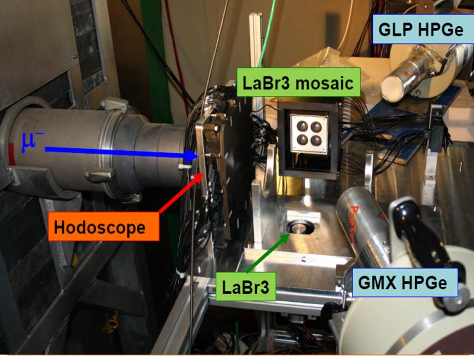
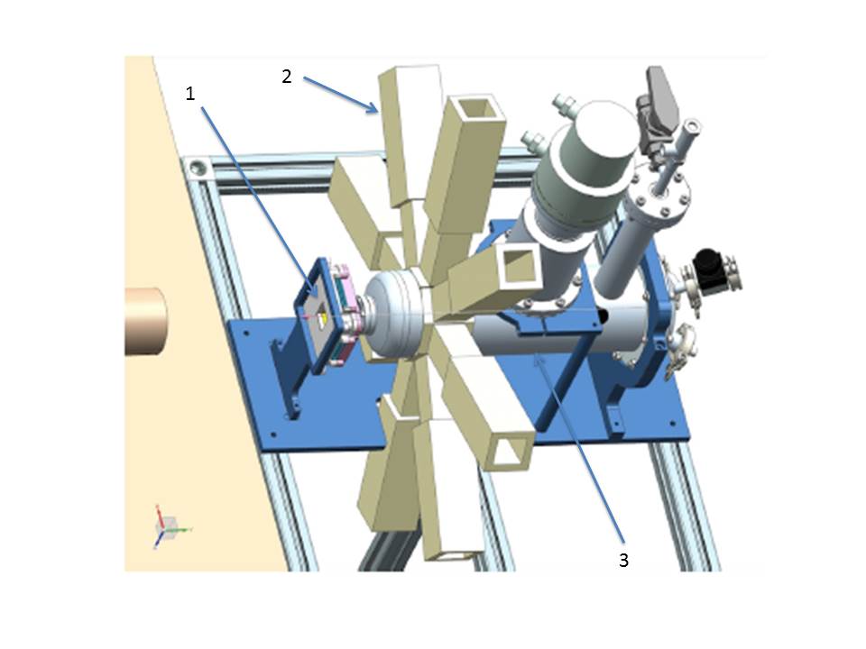
For this experiment, an important issue is the optimal steering of the impinging high intensity pulsed muon beam onto the hydrogen target, to maximize the muonic hydrogen production rate. A system of two beam hodoscopes has been developed for this scope. The first one is based on square mm2 scintillating fibers read by SiPM, for the R484 experiment, which had a data taking in June 2014, while the second one is based on square mm2 scintillating fibers read by SiPM, for the R582 experiment, which instead had a data taking in December 2015 and February 2016. A schematic layout of both experimental setup is shown in figure 1.
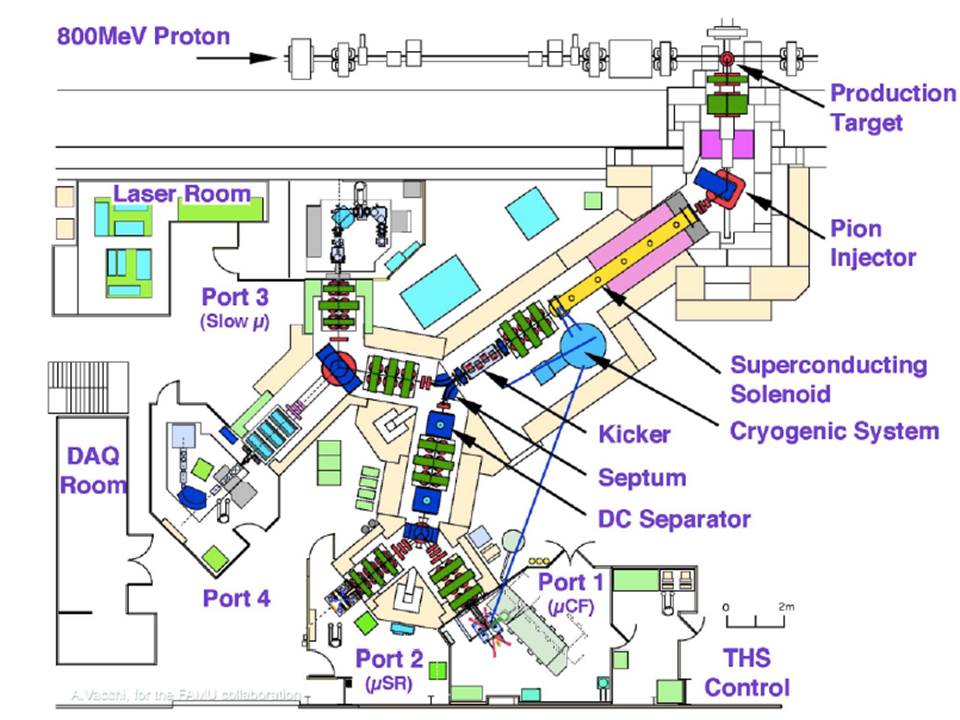
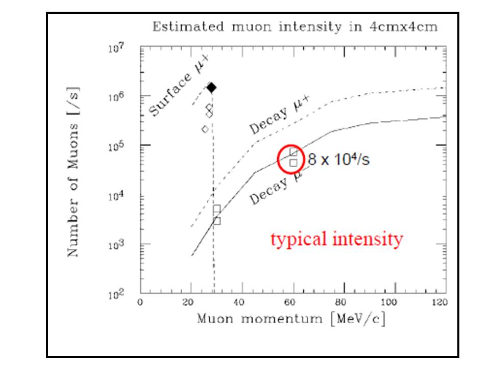
The RIKEN-RAL muon facility at Rutherford Appleton Laboratory (UK) provides high intensity pulsed muon beams at four experimental ports, as shown in figure 2. The ISIS primary proton beam at 800 MeV/c, with a 50 Hz repetition rate, impinges from the left on a secondary carbon target producing pions and then high intensity low energy pulsed muon beams. Surface (20-30 MeV/c) are produced by pions stopping close to the target surface, while decay (20-120 MeV/c) are produced from pion decay outside the target.
The muon beams reflect the primary beam structure: two pulses with a 70 ns FWHM and a 320 ns peak to peak distance are delivered. The FAMU experiment makes use of a negative decay muon beam at 60 MeV/c. The intensity is around /s in a typical size cm2 as shown in the right panel of figure 2. The energy spread is around and the angular divergence around 60 mrad.
2 Construction of the R484 and R582 beam hodoscopes
At the entrance of the FAMU target, the beam profile is nearly flat (see later) and thus we may expect mm in the 70 ns long spill (along transverse x/y directions). This fact puts severe constraints on the beam hodoscope construction and prevents a particle by particle identification.
2.1 The R484 experiment beam hodoscope
The R484 beam hodoscope (see figures 3 and 4 for details) consists of 32+32 scintillating fibers with square cross-section 333Bicron BCF12 single clad, side 3 mm, peak emission nm, trapping efficiency , attenuation length 270 cm, decay time ns, light yield photons/MeV arranged along X/Y axis (orthogonal axis perpendicular to the beamline). The use of square fibers makes the detector response independent from the position of the muon trajectory inside a fiber and minimizes the amount of dead spaces. The fibers have been cut to a length of mm with a Fiberfin4 machine at CERN, that provides directly polished ends ready to use, suited for a detector with a cm2 fiducial area. The fiber thickness of 3+3 mm corresponds approximately to of the range of a 60 MeV/c muon. A muon passing through a fiber produces scintillation light that is detected at one end of the fiber by a cm2 Silicon photomultiplier (SiPM) 444Advansid RGB type, with m cells. For space problems, as the SiPM package footprint is bigger than the fiber size, fibers are read from one edge only, alternating left/right (fibers along X-axis) and up/down (fibers along Y-axis) sides. Fibers were wrapped with an Al-film, m thick, to avoid channel to channel light cross-talk. Single RG174 cables, with MCX connectors on one side and LEMO00 connectors on the other side, convey both the SiPM’s bias (on the external braid shield) and signal ouput (on the cable inner connector). In this way, each SiPM may be powered individually. Each SiPM is mounted on a custom printed board (in groups of 16), as shown in figure 4. SiPMs were hand-soldered on one side of the PCB, facing the scintillating fibers, while MCX connectors were mounted on the other side of the PCB. The detector is housed in a 3D printed ABS case 555printed on a Stratasys Elite Dimension printer, with 0.18 mm resolution.
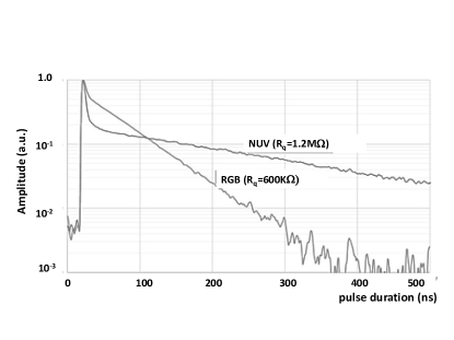
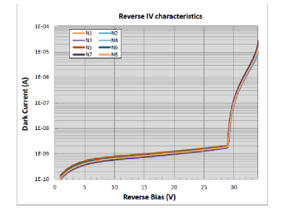
The choice of Advansid RGB SiPMs 666ASD-SiPM3S-P40, in a production batch, with a quenching resistor as photodetectors for the R484 beam hodoscope was dictated by their short pulse duration, their high photon efficiency, well matched to the BC12 fiber peak emission (PDE at nm, with 4 V overvoltage), their low operating voltage (V), their small breakdown voltage dependence from temperature () and their low dark noise, see figure 5 for details. All mm2 SiPMs were individually charaterized to determine their breakdown voltage by measuring their current-voltage charateristic, as shown in the right panel of figure 5.
The detector front-end was based on refurbished electronic boards from the INFN TPS project [5], that provide power to single SiPMs (up to 40 V). This feature allowed to use only Advansid or SENSL SiPMs, excluding Hamamatsu or KETEC ones, that needed higher voltages. The TPS electronic system is based on a VME-like crate, providing power to custom boards and a GPIB module interface. Each TPS electronics board, with 8 individual channels, provided individual channel voltage fine regulation, signal amplification and shaping, signal discrimination and trigger capability, by using the OR of the eight channels of a board. Output signals are also fed into a CAEN V792 QDC for measurement of the charge integrated signal.
The beam hodoscope has been first tested with cosmics at INFN Milano Bicocca, where it has been built, and at the Beam Test Facility (BTF) of the INFN LNF laboratory [6], before the R484 data-taking in mid 2014 at RAL. A custom data-acquisition system was based at first on the Bit3 VME-PCI interface and afterwards on the CAEN V2718 VME-PCI interface. Test beam results at BTF with impinging electrons 777490 MeV kinetic energy, nominal beam profile mm2, beam multiplicity 5 particles/spill, already reported in reference [7], show a signal to noise ratio better than 10 and a single to double MIP separation at . With 60 MeV muons, we expect photons/muon arriving at the mm2 window of a SiPM, giving a collected charge of pC at the QADC input, for a nominal SiPM’s gain of about . In order to match the V792 QADC range (0-400 pC), with the foreseen muon rate at RIKEN-RAL and avoid saturation, 10x attenuators had to be used before the QDC input.
2.2 The R582 experiment beam hodoscope
In the following R582 experiment at RIKEN-RAL, a 1 mm pitch beam hodoscope, to be put in front of the new cryogenic target, was developed.

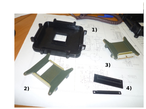
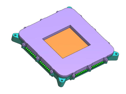
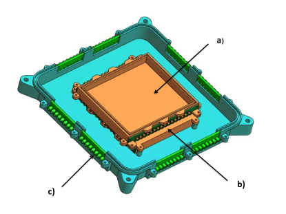
The main requirements were to reduce to a minimum the material in front of the target thin Be window and to try to simplify the layout of the front-end electronics based on one side on VME-like custom TPS boards, with a GPIB to USB control module and on the other side on VME-compliant QDAC and TDCs. To solve the first issue, 32+32 1 mm2 square scintillating Bicron BCF12 fibers 888coated with white Extra Mural Absorber (EMA), to avoid light cross-talk were used. They were arranged in two orthogonal planes along X/Y coordinates, giving a detector fiducial area of mm2 . As before, fibers were cut on a Fiberfin-4 machine at Cern, giving ready-to-use fibers with polished ends. The mechanics layout and the main mechanical components are shown in figure 6. The reduced size of mechanics details of some components gave severe problems for the 3D-printing: issues were solved using an ENVISIONTEC Perfactory 3D-printer at LNGS with a precision better than 0.025 mm.
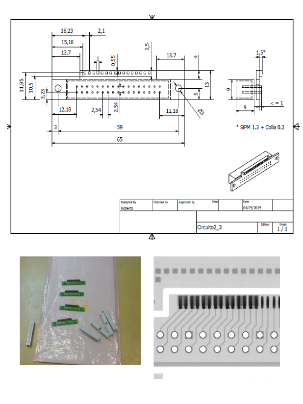
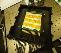
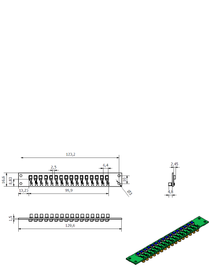
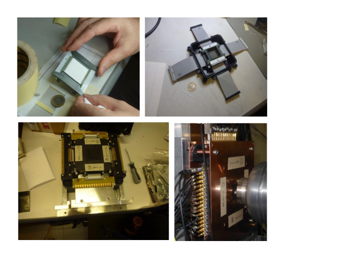
mm2 square SiPMs from Advansid 99940m cells, RGB type were used to detect scintillation light emitted by crossing muons in the detector’s fibers. As the SiPM’s footprint is slightly bigger than the fiber cross-section, fibers had to be read alternating left/right and up/down sides, as for the R484 hodoscope. Each SiPM is mounted on a custom PCB (in groups of 16) as shown in figure 7. On the side facing the fibers the SiPMs have been soldered 101010The mounting was realized at Mevinco srl, Soiano del Lago, Brescia and cross-checked with X-ray imaging, see the right panel of figure 7 for details, while on the opposite side a 34-way flat-cable connector was mounted, to convey bias and take out signals from the SiPMs. Some steps of the mounting of the detector are shown in figure 8, starting from the holder of one plane of fibers to the installation at RIKEN-RAL.
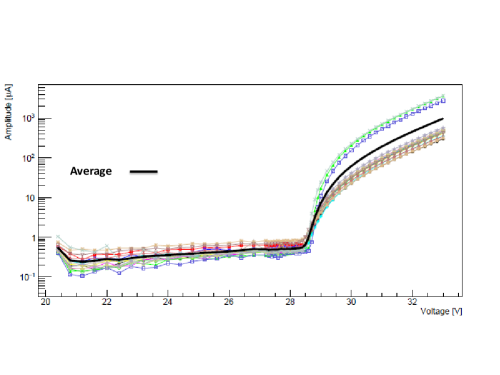
Advansid RGB mm2 SiPMs were chosen as photodetectors for the same reasons that dictated the choice for the mm2 SiPM of the R484 beam hodoscope. All available SiPMs (115 in all) were tested individually to determine their breakdown voltages by measuring their current-voltage characteristic, see the left panel of figure 9 for an example.
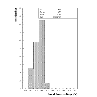
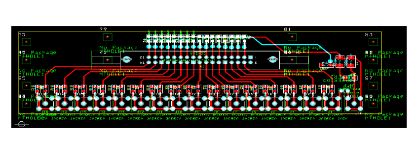
The right panel of figure 9 shows the distribution of their breakdown voltages: on average . It was thus possible, with a suitable selection of the SiPMs to be used, to employ a common voltage for the biasing of the SiPMs of a detector plane. We checked that the 34-way flat cable, that had not a impedance, gave no appreciable distortions to the signal, thanks to its short length. Figure 10 shows one of the four interface boards, with the flat cable socket on one side and angled MCX connectors for signal cables and one LEMO 00 connector for the power line on the other side.
Signals are then fed into a fast FADC 111111CAEN V1742 FAC with 5 GS/s, 12 bit, 1 Vpp input dynamic range, in VME standard operated at a reduced sampling rate of 1 Gs/s to increase the digitizing buffer time.
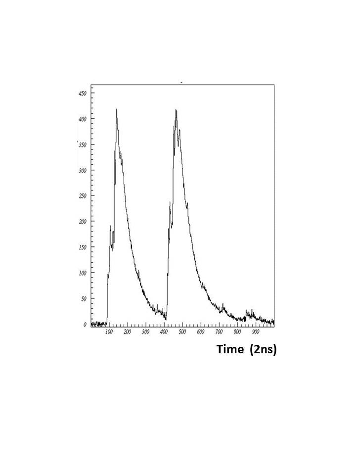
Foreseen developments include the addition of onboard thermistors to ensure long-term stability via correction of SiPMs gain thermal drift and the possibility to use also timing informations from the detector and the monitor of the beam intensity. The left panel of figure 12 shows the FADC waveform for a typical channel, where the two pulses beam structure is clearly visible. Signals were then processed via a custom DAQ sysyem based on a CAEN V2718 VME-PCI interface.
3 Preliminary performances at RIKEN-RAL.
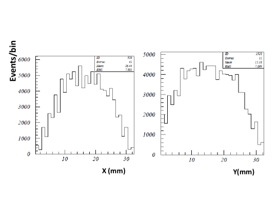
The two beam monitors have been used at RIKEN-RAL to optimize the beam steering inside the target. For the R484 experiment, the integrated charge provided by the CAEN V792 QDC was directly used, while for the R582 experiment the signal waveform for each channel was integrated, after subtracting the baseline, providing the same type of infos.
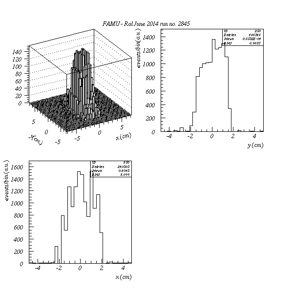
Results for a typical run in R484 are shown in figure 11, while results with standard optics for the R582 run are shown in figure 12. In both cases the beam size is defined by the collimator aperture, with a measured RMS smaller than 10 mm.
4 Conclusions
Two scintillating fibers beam hodoscopes with 1 mm and 3 mm pitch and X/Y readout by SiPM have been developed and used for the measurement of 50-60 MeV/c beam profiles at RIKEN-RAL muon beams. Performances in agreement with expectations are reported and foreseen developments include the possibility to monitor the beam intensity and use timing informations.
Acknowledgements
We would like to thank S. Banfi, M. Geigher (INFN Milano Bicocca), O.Barnaba,R.Nardó (INFN Pavia), A. Iaciofano (INFN Roma Tre) for help in mechanics and electronics. We acknowledge the help of T.Schneider (CERN) for fiber cutting at CERN, D. Orlandi (LNGS) for 3D-printing of some items of the detector at LNGS, N. Serra (Advansid) for SiPMs best handling and of P.Branchini and D.Tagnani (INFN Roma Tre) for the optimal use of TPS electronics . We would like to thank also the staff of ISIS and the RIKEN-RAL facility for the generous help during data-taking and in particular of K. Ishida for advice in the optimal use of our detectors in beam.
References
-
[1]
A. Vacchi et al., Measuring the size of
the proton SPIE Newsroom (2012)
DOI:10.1117/2.1201207.004274;
A. Adamczack et al., Steps towards the hyperfine splitting measurement of the muonic hydrogen ground state: pulsed muon beam and detection system characterization, JINST 11/05 (2016) P05007;
A. Adamczak et al., Theoretical and computational study of the energy dependence of the muon transfer rate from hydrogen to higher Z-gases, Phys. Lett. A379 (2015) 151;
M. Bonesini, The proton radius puzzle, contribution to ICFNP 2016, to be published on EPJ web of Physics -
[2]
A. Adamczack et al., Hyperfine spectroscopy of muonic hydrogen
and the PSI Lamb Shift experiment, Nucl. Instr. Meth. B281
(2012) 72;
D. Bakalov et al., Experimental method to measure the hyperfine splitting of muonic hydrogen , Phys. Lett. A172 (1993) 277;
- [3] A.C. Zemach Proton Structure and the Hyperfine Shift in Hydrogen, Phys. ReV. 104 (1956) 1771.
-
[4]
R.Pohl et al., The size of the proton
Nature 466 (2010) 213;
A. Antognini et al. Proton Structure from the Measurement of 2S-2P Transition Frequencies of Muonic Hydrogen, Science 339 (2013) 417 -
[5]
P. Branchini et al. An FPGA based general purpose
DAQ module for the KLOE-2 experiment, IEEE Trans. Nucl. Sci.
58 (2011) 1544;
R. Pleskac et al. The FIRST experiment at GSI, Nucl. Instr. Meth. A678 (2012) 130. - [6] G. Mazzitelli et al., Commissioning of the DANE beam test facility, Nucl. Instr. Meth. A515 (2003) 524.
- [7] R. Carbone et al., The fiber-SiPM beam monitor of the R484 experiment of the RIKEN-RAL muon facility, JINST 10 (2015) C03007