Thermal memristor and neuromorphic networks for manipulating heat flow
Abstract
A memristor is one of four fundamental two-terminal solid elements in electronics. In addition with the resistor, the capacitor and the inductor, this passive element relates the electric charges to current in solid state elements. Here we report the existence of a thermal analog for this element made with metal-insulator transition materials. We demonstrate that these memristive systems can be used to create thermal neurons opening so the way to neuromophic networks for smart thermal management and information treatment.
pacs:
44.10.+i, 05.45.-a, 05.60.-kDuring almost two centuries it was admitted that only three fundamental passive elements, the resistor, the capacitor and the inductor were the building blocks to relate voltage , current , charge , and magnetic flux in solid elements. However, in 1971 Chua Chua envisioned, through symmetry arguments, the existence of another fundamental element, the memristor a two-terminal non-linear component relating electric charge to flux in electronics circuits. In 2008 Strukov et al. Strukov shown using tunable doped metal-oxide-semiconductors films that this vision was true. The basic mathematical modelling of a memristive system typically takes the following form
| (1) |
where is a state variable and is a generalized resistance which depends on this variable and on either the voltage (i.e. for a voltage-controlled memristor) or on the intensity (i.e. for a current-controlled memristor). The distinction between memristive systems and arbitrary dynamical systems is the fact that the voltage (output) is always zero when the current (input) is zero, resulting in zero-crossing Lissajous curves. In this Letter we extend this concept to the heat transport by conduction and we explore the possibilities offered by thermal memristive systems to manage heat exchanges and make information treatment with heat rather than with electric currents as suggested by Li et al. BaowenLiEtAl2012 .
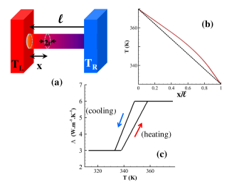
The basic system we consider is sketched on Fig. 1-a. It is a cylindrical wire of radius and length made with vanadium dioxide () a metal-insulator transition (MIT) material. This wire is in contact on its two extremities with two themal reservoirs at temperature and , respectively. The MIT material is able to change its thermal conductivity following a hystereris curve (see Fig. 1-b) with respect to the temperature around a critical temperature . Beyond the wire tends to become metallic (amorphous) and for sufficiently high temperatures its thermal conductivity is . At the opposite, below tends to be crystalline (i.e. insulating) and at sufficiently low temperature. However the evolution between these two extremes values follows a hysterezis loop Oh with respect to the temperature. Recent works have demonstrated that the thermal bistability of these MITs can be exploited to store thermal information BaowenLi3 ; Xie ; Slava ; DyakovMemory .
By changing the temperature gradient along the wire, the phase front moves along the wire so that its thermal resistance changes with respect to the temperature difference between the two reservoirs. In steady state regime and without convection on the external surface of wire, the heat conduction obeys the following equation
| (2) |
By applying a Kirchoff’s transformation
| (3) |
on the thermal conductivity , it is straighforward to show that the temperature profile along the wire is solution of the following equation
| (4) |
Using the piecewise decomposition
| (5) |
of the conductivity with respect to the temperature, an explicit expression for the temperature profile can be derived SupplMat from (4). In this decomposition, the subscript refers to the heating () or the cooling () phase.
The flux flowing accross a wire of section is related to the temperature difference between the two reservoirs and to the thermal resistance by the simple system of equations
| (6) |
where the state variables and represent here the location along the wire below (resp. beyond) which the MIT material becomes metallic (resp. insulating) during the heating or cooling phase. denotes the function which drive the location of phase front inside the wire. Note that, depending on the thermal boundary conditions applied on the wire, these points can potentially be located outside of the wire (see SupplMat ). The thermal resistance is obtained by summing the resistances in series along wire below , between and and beyond . Accordingly
| (7) |
with , and . Notice that these resistances can vanish depending on the value of state variables and .
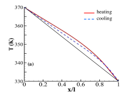
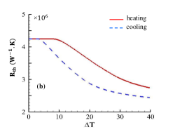
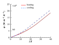
In Fig. 2(a) are plotted the temperature profiles along a wire under a temperature gradient during the cooling and heating steps. Contrary to a classical conduction process those temperature profiles are not linear because of the temperature dependence of the thermal resistance as shown in Fig. 2(b). It results from this nonlinearity a nonlinear variation of flux crossing the wire as well (Fig. 2(c)) with respect to the temperature difference applied on it.
Following a similar approach as in the Chua′ s work Chua , based on symmetry arguments, we can derive the equivalence rules between the electronic and the thermal problem for the fundamental quantities.
| (8) |
where and denote the thermal charge obtained by time integration of heat flux and the classical electric charge, respectively. It follows that the thermal capacity can be defined as
| (9) |
As for the thermal analog of magnetic flux, it is given by
| (10) |
Finally, the thermal memristance ("the missing element") reads
| (11) |
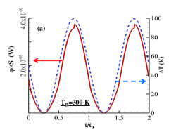
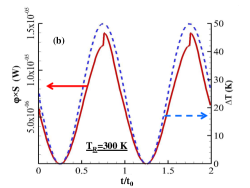
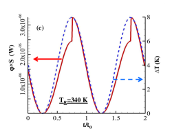
A key point for a memristor is its operating mode under a transient excitation. Provide the timescale at which the boundary conditions varie is large enough compared with the relaxation time of temperature field inside the wire itself, the variation of flux crossing the system can be calculated from relation (6). In typical solids, the thermalization timescale varies between few picosecond at nanoscale (phonon-relaxation time) to few microsecond at microscale (diffusion time , being the thermal diffusivity). The application of an external bias across the system moves the position of state variables and causing a time evolution of the thermal resistance . In Fig. 3 we show the time evolution of this flux for a sinusoidal variation of with a period large enough compared to the relaxation time of memristor. Since the effective conductance (resp. resistance) of memristor increases (resp. decreases) when the system switch from the heating to the cooling phase we observe a significant enhancement of heat flux (up to ) flowing through the memristor each time decays. This sharp variation of physical properties can be exploited to design basic neuronal circuits and make logical operations with thermal signals.
Recent works have demonstrated the possibility to make such logical operations with acoustic phonons BaowenLi2 ; BaowenLi3 ; BaowenLiEtAl2012 or thermal photons OteyEtAl2010 ; BasuFrancoeur2011 ; Huang ; Dames ; PBA_APL ; Ito ; van Zwol1 ; PBA_PRL2014 by using phononic and photonic counterpart of diodes and transistors. Here, we demonstrate that memristive systems can be an alternative to these systems. To show that, let us consider a simple neuron McCulloch made with two memristors connected to the same node (output) as sketched in Fig. 4. One temperature () is used as an input signal while the second temperature plays the role of a simple bias and is held at a fixed value. The time variation of the first input (related to the power added or extracted from the solid in contact to the left side of first memristor) set the second input parameter. Depending on its sign (i.e. heating or cooling process) this parameter can be assimilated to a binary parameter as shown on the truth table in Fig. 4. Then, the output temperature is obtained with respect to and by solving, in steady state regime, the energy balance equation
| (12) |
According to the change in the two inputs signals, a sharp transition for the output can be observed (Fig. 4). This transition occurs precisely when the memristors switches from their heating to their cooling operating mode. The horizontal lines in Fig.4 given by and (where ) allow to define the and states for the gate. By using the truth table shown in Fig. 4 it appears that this simple neuron operates as an AND gate. Beyond this logical operation more complex neuronal architectures, where the memristors are used as on/off temperature dependent bistable switchs, can be designed to implement other boolean operations.
To summarize, we have introduced the concept of phase-change thermal memristor and shown that it constitutes a fundamental building block for the implementation of basic logical operations with neurons entirely driven by heat. The relaxation dynamic of these memristors combined with the massively parallelism of neuronal networks make promising these systems both for thermal computing and active thermal management at a submicronic time scale.
Supplementary Material
In the supplementary material we give the analytical expression of parameter and of temperature field inside a memristor with respect to the temperature difference apply on it.
Acknowledgments
P.B.-A. acknowledges discussions with Dr I. Latella
References
- (1) L. O. Chua, IEEE Trans. Circuit Theory 18, 507-519 (1971).
- (2) D. B. Strukov, G. S. Snider, D. R. Stewart and R. S. Williams, Nature, 453, 1 May (2008).
- (3) N. Li, J. Ren, L. Wang G. Zhang, P. Hänggi, and B. Li, Rev. Mod. Phys. 84, 1045 (2012).
- (4) D.W. Oh, C Ko, S Ramanathan, DG Cahill. APL, 96, 151906 (2010).
- (5) L. Wang and B. Li, Phys. Rev. Lett. 101, 267203 (2008).
- (6) R. Xie, C. Ting Bui, B. Varghese, Q. Zhang, C. Haur Sow, B. Li and J. T. L. Thong, Adv. Funct. Mater. 21, 1602 (2011).
- (7) V. Kubytskyi, S.-A. Biehs and P. Ben-Abdallah, Phys. Rev. Lett. 113, 074301 (2014).
- (8) S.A. Dyakov, J. Dai, M. Yan, M. Qiu, J.of Phys. D: Applied Physics 48 (30), 305104 (2015).
- (9) See EPAPS Document No. [number will be inserted by publisher].
- (10) L. Wang, B. Li, Phys. Rev. Lett. 99, 177208 (2007).
- (11) C. R. Otey, W. T. Lau, and S. Fan, Phys. Rev. Lett. 104, 154301 (2010).
- (12) S. Basu and M. Francoeur, Appl. Phys. Lett. 98, 113106 (2011).
- (13) J. G. Huang, Q. Li, Z. H. Zheng and Y. M. Xuan, Int. J. Heat and Mass Trans., 67, 575 (2013).
- (14) Z. Chen, C. Wong, S. Lubner, S. Yee, J. Miller, W. Jang, C. Hardin, A. Fong, J. E. Garay and C. Dames, Nature Comm., 5, 5446 (2014).
- (15) P. Ben-Abdallah and S.-A. Biehs, Appl. Phys. Lett. 103, 191907 (2013).
- (16) K. Ito, K. Nishikawa, H. Lizuka and H. Toshiyoshi, Appl. Phys. Lett. 105, 253503 (2014).
- (17) P. van Zwol, K. Joulain, P. Ben-Abdallah, and J. Chevrier, Phys. Rev. B, 84, 161413(R) (2011).
- (18) P. Ben-Abdallah and S.-A. Biehs, Phys.Rev. Lett. 112, 044301 (2014).
- (19) W. S. McCulloch and W. Pitts, Bull. Mathematical Biophysics, 5, 115 (1943).