Magnetization reversal by superconducting current in Josephson junctions
Abstract
We study magnetization reversal in a Josephson junction with direct coupling between magnetic moment and Josephson current. Our simulations of magnetic moment dynamics show that by applying an electric current pulse, we can realize the full magnetization reversal. We propose different protocols of full magnetization reversal based on the variation of the Josephson junction and pulse parameters, particularly, electric current pulse amplitude, damping of magnetization and spin-orbit interaction. We discuss experiments which can probe the magnetization reversal in -junctions.
Spintronics, which deals with an active control of spin dynamics in solid state systems, is one of the most rapidly developing field of condensed matter physics sdsrev . An important place in this field is occupied by superconducting spintronics dealing with the Josephson junctions (JJ) coupled to magnetic systems linder15 . The possibility of achieving electric control over the magnetic properties of the magnet via Josephson current and its counterpart, i.e., achieving magnetic control over Josephson current, recently attracted a lot of attention buzdin05 ; bergeret05 ; golubov04 . Spin-orbit coupling plays a major role in achieving such control. For example, in superconductor/ferromagnet/superconductor (S/F/S) JJs, its presence in a ferromagnet without inversion symmetry provides a mechanism for a direct (linear) coupling between the magnetic moment and the superconducting current. In such junctions, called hereafter -junction, time reversal symmetry is broken, and the current–phase relation is given by , where the phase shift is proportional to the magnetic moment perpendicular to the gradient of the asymmetric spin-orbit potential, and also to the applied current.buzdin08 ; krive05 ; reynoso08 . Thus such JJs allow one to manipulate the internal magnetic moment by Josephson current buzdin08 ; konschelle09 . The static properties of structures are well studied both theoretically and experimentally; however, the magnetic dynamics of these systems has not been studied in detail beyond a few theoretical works buzdin08 ; konschelle09 ; waintal02 ; braude08 ; linder83 ; cai10 ; chud2016 .
The spin dynamics associated with such -junctions was studied theoretically in Ref. konschelle09, . The authors considered a -junction in a low frequency regime which allowed usage of quasi-static approach to study magnetization dynamics. It was demonstrated that a DC superconducting current produces a strong orientation effect on the magnetic moment of the ferromagnetic layer. Thus application of a DC voltage to the -junction is expected to lead to current oscillations and consequently magnetic precession. This precession can be monitored by the appearance of higher harmonics in current-phase relation; in addition, it also leads to the appearance of a DC component of the current which increases near a ferromagnetic resonancekonschelle09 . It is then expected that the presence of external radiation in such a system would lead to several phenomena such as appearance of half-integer steps in the current-voltage (I-V) characteristics of the junction and generation of an additional magnetic precession with frequency of external radiation konschelle09 .
In this paper we study the magnetization reversal in -junction with direct coupling between magnetic moment and Josephson current and explore the possibility of electrically controllable magnetization reversal in these junctions. We carry out investigations of the magnetization dynamics for two types of applied current pulse: rectangular and Gaussian forms. An exact numerical simulation of the dynamics of magnetic moment of the ferromagnetic layer in the presence of such pulses allows us to demonstrate complete magnetization reversal in these systems. Such reversal occurs for specific parameters of the junction and the pulse. We chart out these parameters and suggest a possible way for determination of spin-orbit coupling parameter in these systems. We discuss the experiment which can test our theory.
In order to study the dynamics of the S/F/S system, we use the method developed in Ref. konschelle09, . We assume that the gradient of the spin-orbit potential is along the easy axis of magnetization taken to be along . The total energy of this system can be written as
| (1) |
where is the phase difference between the superconductors across the junction, is the external current, , and is the Josephson energy. Here is the flux quantum, is the critical current, , is Fermi velocity, , is the length of layer, is the exchange field of the layer, , the parameter characterizes a relative strength of spin-orbit interaction, is the anisotropic constant, and is the volume of the layer.
The magnetization dynamics is described by the Landau-Lifshitz-Gilbert equationbuzdin05 (see also Supplementary Material) which can be written in the dimensionless form as
| (2) |
where is a phenomenological Gilbert damping constant, , and . The satisfy the constraint . In this system of equations time is normalized to the inverse ferromagnetic resonance frequency , is the gyromagnetic ratio, and . In what follows, we obtain time dependence of magnetization , phase difference and normalized superconducting current via numerical solution of Eq.(2).
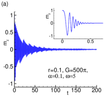
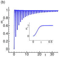
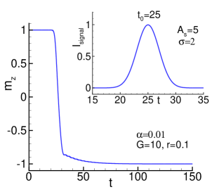
Let us first investigate an effect of superconducting current on the dynamics of magnetic momentum. Our main goal is to search for cases related to the possibility of the full reversal of the magnetic moment by superconducting current. In Ref.konschelle09, the authors have observed a periodic reversal, realized in short time interval. But, as we see in Fig. 1, during a long time interval the character of dynamics changes crucially. At long times, becomes parallel to -axis, as seen from Fig.1(b)) demonstrating dynamics of . The situation is reminiscent of Kapitza pendulum (a pendulum whose point of suspension vibrates) where the external sinusoidal force can invert the stability position of the pendulum.kapitza Detailed features of Kapitza pendulum manifestation will be presented elsewhere.
The question we put here is the following: is it possible to revers the magnetization by the electric current pulse and then preserve this reversed state. The answer may be found by solving the system of equations (2) together with Josephson relation , written in the dimensionless form. It was demonstrated in Ref.cai10, that using a specific time dependence of the bias voltage, applied to the weak link leads to the reversal of the magnetic moment of the nanomagnet. The authors showed the reversal of nanomagnet by linearly decreasing bias voltage (see Fig.3 in Ref.cai10, ). The magnetization reversal, in this case, was accompanied by complex dynamical behavior of the phase and continued during a sufficiently long time interval.
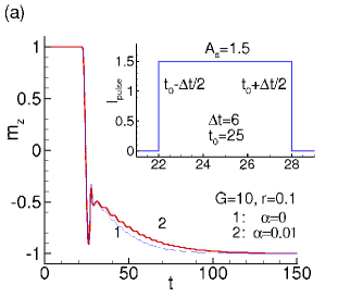
In contrast, in the present work we investigate the magnetization reversal in the system described by the equations (2) under the influence of the electric current pulse of rectangular and Gaussian forms. The effect of rectangular electric current pulse are modeled by in the time interval () and in other cases. The form of the current pulse is shown in the inset to Fig.2(a).
Here we consider the JJ with low capacitance C ( , where is the inductance of the JJ and is its resistance), i.e., we do not take into account the displacement current. So, the electric current through JJs is
| (3) |
where , , - critical current, - resistance of JJ, - characteristic frequency. We solved the system of equations ( 2) together with equation ( 3) and describe the dynamics of the system. Time dependence of the electric current is determined through time dependence of phase difference and magnetization components , , .
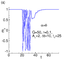
We first study the effect of the rectangular pulse shown in the inset to Fig.2(a). It is found that the reversal of magnetic moment can indeed be realized at optimal values of JJ () and pulse () parameters . An example of the transition dynamics for such reversal of with residual oscillation is demonstrated in Fig. 2(a); the corresponding parameter values are shown in the figure.
Dynamics of the magnetic moment components, the phase difference and superconducting current is illustrated in Fig.2(b). We see that in the transition region the phase difference changes from to and, correspondingly, the superconducting current changes its direction twice. This is followed by damped oscillation of the superconducting current.
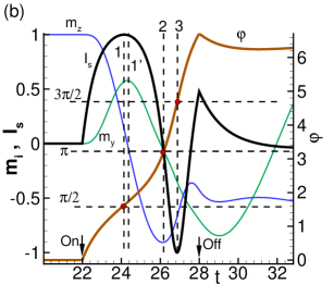
There are some characteristic time points in Fig.2(b), indicated by vertical dashed lines. Line 1 corresponds to a phase difference of and indicate maximum of superconducting current . The line which corresponds to the maximum of , and has a small shift from line 1. This fact demonstrates that, in general, the characteristic features of and time dependence do not coincide with the features on the , i.e., there is a delay in reaction of magnetic moment to the changes of superconducting current. Another characteristic point corresponds to the . At this time line 2 crosses points , , and minimum of . At time moment when line 3 crosses minimum of . When pulse is switched off, the superconducting current starts to flow through the resistance demonstrating damped oscillations and causing residual oscillations of magnetic moment components. Note also, that the time at which the current pulse ends () is actually does not manifest itself immediately in the (and not shown here ) dynamics. They demonstrate continuous transition to the damped oscillating behavior.
Fig. 2(b) provides us with a direct way of determining the spin-orbit coupling strength in the junction via estimation of . For this, we note that the can be determined, up to a initial time-independent constant , in terms of the voltage across the junction. Moreover, the maxima and minima of occurs at times and (see Fig. 2(b)) for which Eliminating from these equations, one gets
| (4) |
which allows us, in principal, to determine in terms of the magnetization at the position of maxima and minima of the supercurrent and the voltage across the junction. We stress that for the experimental realization of proposed method one would need to resolve the value of the magnetization at the time difference of the order of - c. At the present stage the study of the magnetization dynamics with such a resolution is extremely challenging. To determine the spin-orbit coupling constant experimentally it may be more convenient to vary the parameters of the current pulse and study the threshold of the magnetic moment switching.
The dynamics of the system in the form of magnetization trajectories in the planes and during a transition time interval at the same parameters of the pulse and JJ at is presented in Fig.3.
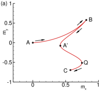
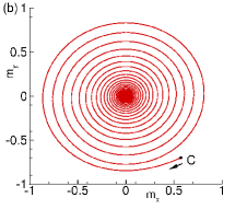
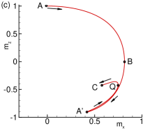
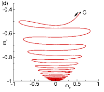
We see that magnetic moment makes a spiral rotation approaching the state with after switching off the electric current pulse. The figures show clearly the specific features of the dynamics around points , and and damped oscillations of the magnetization components (see Fig.3(b) and Fig.3(d)). The cusps at point B in Fig.3(a) corresponds just to the change from an increasing of absolute value of to its decreasing and, opposite, at point in Fig.3(c). The behavior of magnetic system happens to be sensitive to the parameters of the electric current pulse and JJ. In the Supplement we show three additional protocols of the magnetization reversal by variation of , and .
It is interesting to compare the effect of rectangular pulse with the Gaussian one of the form
| (5) |
where denotes the full width at half-maximum of the pulse and is its maximum amplitude at . In this case we also solve numerically the system of equations (2) together with equation (3) using (5). An example of magnetic moment reversal in this case is presented in Figure 4, which shows the transition dynamics of for the parameters , , , at small dissipation .
We see that the magnetization reversal occurs more smoothly in compare with a rectangular case.
We also note that very important role in the reversal phenomena belongs to the effect of damping. It’s described by term with in the system of equations (2), where is a damping parameter. The examples of the magnetization reversal at , and different values of are presented in Fig.5.
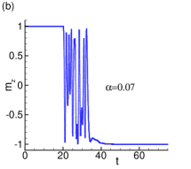
We see that dissipation can bring the magnetic system to full reversal, even if at the system does not demonstrate reversal. Naturally, the magnetic moment, after reversal, shows some residual oscillations as well. We stress that the full magnetization reversal is realized in some fixed intervals of dissipation parameter. As expected, the variation of phase difference by reflects the maxima in the time dependence of the superconducting current. Fig.6 demonstrates this fact.
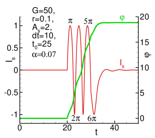
The presented data shows that the total change of phase difference consists of , which corresponds to the six extrema in the dependence . After the full magnetization reversal is realized, the phase difference shows the oscillations only.
One of the important aspect of the results that we obtain here is the achievement of a relatively short switching time interval for magnetization reversal. As we have seen in Figs. 2(a) and 4, the time taken for such reversal is which translate to seconds for typical . We note that this amounts to a switching time which is of that obtained in Ref. cai10, .
Experimental verification of our work would involve measurement of in a junction subjected to a current pulse. For appropriate pulse and junction parameters as outlined in Figs. 4 and 5, we predict observation of reversal of at late times . Moreover, measurement of at times and where reaches maximum and minimum values and the voltage across the junction between these times would allow for experimental determination of via Eq. 4.
As a ferromagnet we propose to use a very thin layer on dielectric substrate. Its presence produces the Rashba-type spin-orbit interaction and the strength of this interaction will be large in metal with large atomic number . The appropriate candidate is a permalloy doped with .Hrabec In the spin-orbit interaction play a very important role in electronic band formation and the parameter , which characterizes the relative strength of the spin-orbit interaction is . On the other hand, the doping of permalloy up to 10 did not influenced significantly its magnetic properties Hrabec and then we may expect to reach in this case 0.1 also. If the length of layer is of the order of the magnetic decaying length , i.e. , we have . Another suitable candidate may be a bilayer, ferromagnet without inversion symmetry like MnSi or FeGe. If the magnetic moment is oriented in plane of the F layer, than the spin-orbit interaction should generate a Josephson junctionbuzdin08 with finite ground phase difference. The measurement of this phase difference (similar to the experiments in Ref.Szombati, ) may serve as an independent way for the parameter evaluation. The parameter has been evaluated in Ref.konschelle09, for weak magnetic anisotropy of permalloy (see Ref.Rusanov, ) and junction with and K as . For stronger anisotropy we may expect .
In summary, we have studied the magnetization reversal in -junction with direct coupling between magnetic moment and Josephson current. By adding the electric current pulse, we have simulated the dynamics of magnetic moment components and demonstrate the full magnetization reversal at some parameters of the system and external signal. Particularly, time interval for magnetization reversal can be decreased by changing the amplitude of the signal and spin-orbit coupling. The observed features might find an application in different fields of superconducting spintronics. They can be considered as a fundamental basis for memory elements, also.
See supplementary material for demonstration of different protocols of the magnetization reversal by variation of Josephson junction and electric current pulse parameters.
Acknowledgment: The authors thank I. Bobkova and A. Bobkov for helpful discussion. The reported study was funded by the RFBR research project 16–52–45011India, 15–29–01217, the the DST-RFBR grant INT/RUS/RFBR/P-249, and the French ANR projects ”SUPERTRONICS”.
References
- (1) I. Zutic, J. Fabian, and S. Das Sarma, Rev. Mod. Phys. 76, 323 (2004).
- (2) Jacob Linder and W. A. Jason Robinson, Nature Physics, 11, 307 (2015).
- (3) A. I. Buzdin, Rev. Mod. Phys., 77, 935 (2005).
- (4) F. S. Bergeret, A. F. Volkov, and K. B. Efetov, Rev. Mod. Phys., 77, 1321 (2005).
- (5) A. A. Golubov, M. Y. Kupriyanov, and E. Ilichev, Rev. Mod. Phys. , 76, 411 (2004).
- (6) A. Buzdin, Phys. Rev. Lett., 101, 107005 (2008).
- (7) I. V. Krive, A. M. Kadigrobov, R. I. Shekhter, and M. Jonson, Phys. Rev. B 71, 214516 (2005).
- (8) A. A. Reynoso, G. Usaj, C. A. Balseiro, D. Feinberg, and M. Avignon, Phys. Rev. Lett. 101, 107001 (2008).
- (9) F. Konschelle, A. Buzdin, Phys. Rev. Lett ., 102 , 017001 (2009).
- (10) X. Waintal and P. W. Brouwer, Phys. Rev., B 65, 054407 (2002).
- (11) V. Braude and Ya. M. Blanter, Phys. Rev. Lett., 100, 207001 (2008).
- (12) J. Linder and T. Yokoyama, Phys. Rev., B 83, 012501 (2011).
- (13) Liufei Cai and E. M. Chudnovsky, Phys. Rev., B 82, 104429 (2010).
- (14) Eugene M. Chudnovsky, Phys. Rev., B 93, 144422 (2016).
- (15) P. L. Kapitza, Soviet Phys. JETP, B21, 588-592 (1951); Usp. Fiz. Nauk, B44, 7-15 (1951).
- (16) A. Hrabec, F. J. T. Goncalves, C. S. Spencer, E. Arenholz, A. T. N Diaye, R. L. Stamps and Christopher H. Marrows, Phys. Rev. B 93, 014432 (2016).
- (17) D. B. Szombati, S. Nadj-Perge, D. Car, S. R. Plissard, E. P. A. M. Bakkers and L. P. Kouwenhoven, Nture Physics 12, 568 (2016).
- (18) A. Yu. Rusanov, M. Hesselberth, J. Aarts, A. I. Buzdin, Phys. Rev. Lett. 93, 057002 (2004).
Supplementary Material to “Magnetization reversal by superconducting current in Josephson junctions”
I Geometry and equations
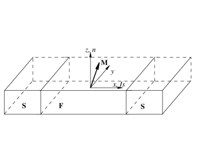
Geometry of the considered -junctionkonschelle09 is presented in Fig. 7. The ferromagnetic easy-axis is directed along the z-axis, which is also the direction n of the gradient of the spin-orbit potential. The magnetization component is coupled with Josephson current through the phase shift term , where is the superconducting order parameter ( is along the x-axis in the system considered here).
In order to study the dynamics of the S/F/S system, we use the method developed in Ref. konschelle09, . We assume that the gradient of the spin-orbit potential is along the easy axis of magnetization taken to be along . The total energy of this system is determined by the expression (S1) in the main text.
The magnetization dynamics is described by the Landau-Lifshitz-Gilbert equationbuzdin05
| (6) |
where is the gyromagnetic ratio, is a phenomenological Gilbert damping constant, and . The effective field experienced by the magnetization is determined by , so
| (7) |
where , and .
II Magnetization reversal under electric current pulse
Magnetic system is very sensitive to the parameters of the electric current pulse and Josephson junction. Here we show three additional protocols of the magnetization reversal by variation of , and .
II.1 Effect of -variation
Figure 8 demonstrates the magnetization reversal by changing pulse parameter .
We see that change of pulse amplitude to reverses magnetic moment. At this feature is still conserved, but disappears at larger values.
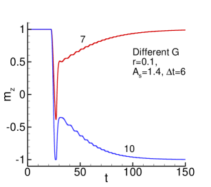
II.2 Effect of -variation
Figure 9 demonstrates the magnetization reversal by changing Josephson junction parameter .
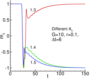
II.3 Effect of -variation
Figure 10 demonstrates the magnetization reversal by changing Josephson junction parameter of spin-orbital coupling .
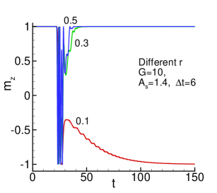
Figure 10 demonstrates the magnetization reversal by changing Josephson junction parameter of spin-orbital coupling .We see that there is a possibility of magnetization reversal around . In this case a decrease of spin-orbit parameter may lead to the magnetization reversal also. The magnetization reversal depends on the other parameters of the system and, naturally, the minimal value of parameter depends on their values. In particular case presented here it is around 0.05.