Work-sharing of qubits in topological error corrections
Abstract
Topological error-correcting codes, such as surface codes and color codes, are promising because quantum operations are realized by two-dimensionally (2D) arrayed quantum bits (qubits). However, physical wiring of electrodes to qubits is complicated, and 3D integration for the wiring requires further development of fabrication technologies. Here, we propose a method to reduce the congestion of wiring to qubits by just adding a SWAP gate after each controlled-NOT (CNOT) gate. SWAP gates exchange roles of qubits. Then, the roles of qubits are shared between different qubits. We found that our method transforms the qubit layout and reduces the number of qubits that cannot be accessed two-dimensionally. We show that fully 2D layouts including both qubits and control electrodes can be achieved for surface and color codes of minimum sizes. This method will be beneficial to simplifications of fabrication process of quantum circuits in addition to improvements of reliability of qubit system.
pacs:
03.67.Lx, 03.67.Mn, 73.21.LaI Introduction
Solid-state quantum computers Yamamoto ; Niskanen0 ; Mooij ; Wallraff ; Xmon1 ; Xmon2 ; Ladd ; Schoelkopf have made significant progress recently in experiments of quantum error corrections stabilizer ; Kelly ; IBM . Topological error-correcting codes, such as surface codes Kitaev1 ; Kitaev2 ; Fowler1 ; Fowler2 ; Hill ; Devitt and color codes Bombin ; Landahl ; Jones ; Nigg , have been intensively investigated because quantum operations are realized through physical interactions between nearest neighboring qubits. However, physical wiring of electrodes to qubits is complicated and 3D integration for the wiring requires further development of fabrication technologies Brecht . The complexity of wiring is mainly attributable to connections to syndrome-qubits from data-qubits. Although quantum annealing machines based on superconducting qubits have already been developed Dwave , in order to realize quantum computation, accurate control of quantum error correction is necessary.
Here, we propose a method to reduce the congestion of wiring to qubits. We just add a SWAP gate Nielsen after each controlled-NOT (CNOT) gate. Because SWAP gates exchange roles of qubits, the roles of syndrome measurements are shared between different qubits. This transforms the qubit layout and reduces the number of qubits that cannot be accessed two-dimensionally. In particular, we show that fully 2D layouts including both qubits and control electrodes can be achieved for surface and color codes of minimum sizes. Because a CNOT gate is indispensable to every quantum computer, the work-sharing of qubits by SWAP gates will be applicable to general quantum circuits to improve uneven workloads of qubits.
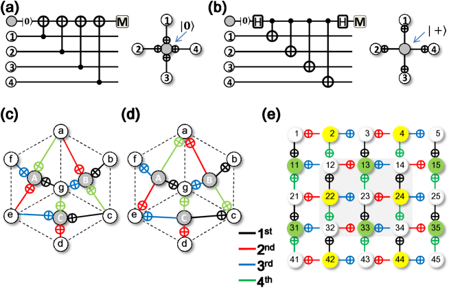
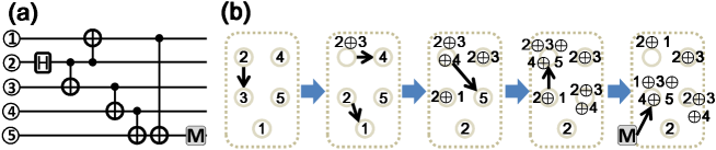
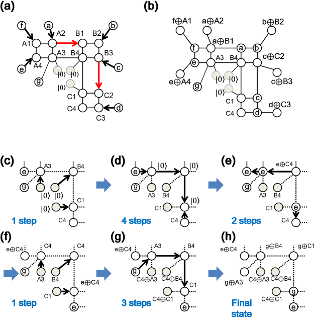
Topological codes are based on the stabilizer formalism Nielsen ; Gottesman , where a parity check process is carried out by summing ‘1’ of data-qubits by using CNOT operations. Errors can be detected by change of the parity. As an example, when a wave function of four data-qubits is given by and a syndrome-qubit is initialized as , the measurement process of a -type check operator (-check) is given by (Fig.1(a)), where denotes summation modulo 2. Similarly, the measurement process of a -type check operator (-check) is illustrated in Fig.1(b) (). When the number of data-qubits increases, the corresponding number of wirings to a single syndrome-qubit increases. Physical wires have a finite width and when many wires are arranged closely, the crosstalk problem also appears Xmon2 . Thus, it is desirable to avoid the concentration of wires in a small space.
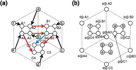
Using local interactions between nearest-neighbor qubits on a two-dimensional (2D) physical plane, surface codes Kitaev1 ; Kitaev2 ; Fowler1 ; Fowler2 ; Hill ; Devitt and color codes Bombin ; Landahl ; Jones ; Nigg have a high tolerance against errors. However, control gate electrodes are not generally placed in the same physical plane as qubits, and vertical access to qubits is unavoidable. Figures 1(c) and 1(d) show -checks and checks of the 7-qubit color code, respectively. The three syndrome-qubits ‘A-C’ are connected to seven data-qubits, where the data-qubit ‘g’ should be accessed from the vertical direction by stacking an additional wiring layer. Figure 1(e) shows a distance-3 surface code, where -checks and -checks are performed simultaneously Kitaev1 ; Kitaev2 ; Fowler1 ; Fowler2 . The code-distance is the measure of a code in which physical errors can be corrected by repeated measurements, and corresponds to the array size in the surface code. In this code, the inner nine qubits should be accessed vertically Fowler1 . Thus, many stabilizer codes lead to a concentration of wires to syndrome-qubits and the complexity of wiring between qubits is unavoidable Xmon2 ; IBM . Because qubits are sensitive to decoherence, the fabrication process of wiring is particularly difficult in view of the state-of-the-art techniques.
Our method for reducing wiring congestion is to just add a SWAP gate after each CNOT gate in stabilizer measurements. SWAP gates are widely used in quantum operations and exchange qubit states without changing system entanglement DiV ; DiV2 . The combination of a SWAP gate and a CNOT gate (hereafter a ‘CNOT+SWAP gate’) shifts the role of syndrome-qubits, and reduces the congestion of wiring. The replacement of CNOT gates by CNOT+SWAP gates is effective in stabilizer measurements because syndrome measurements are repeated many times. We show that this method changes qubit layouts, and importantly, for codes of small sizes, wiring can be set on the same physical plane as qubit array.
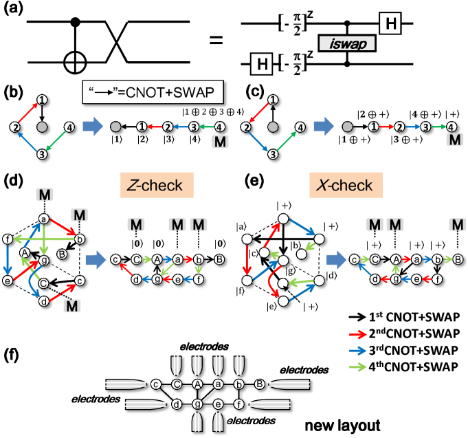
The insertion of a SWAP gate in each CNOT gate imposes no overhead but rather it is advantageous when physical interactions between qubits are interactions XY . The CNOT+SWAP gate can be performed directly by the interaction (iSWAP) with single-qubit rotations (Fig.2(a)) XY ; Schuch . On the other hand, a CNOT gate needs two iSWAP gates, which makes the CNOT operation complicated and more fragile. Thus, in the case of the interaction, the replacement of CNOT gates by CNOT+SWAP gates makes quantum operations more reliable and saves operation time iSWAP ; iSWAP2 ; Wei . Moreover, high-precision iSWAP gates are experimentally feasible Bialczak ; Dewes ; McKay .
This paper is organized as follows: In Sec. II we show an example of the application of replacement of CNOT gate by CNOT+SWAP gate to fundamental stabilizer measurement. In Sec. III, we show layout changes of a minimum 7-qubit color code and the second smallest color code by our method. In Sec. IV, we first show layout changes of standard surface codes. Next we consider the application of our method to a rotated surface code, and we also show results of numerical simulations of logical error probabilities. Sec. V is devoted to a conclusion. In Appendix, we show detailed explanations of the numerical simulation of Sec. IV and a process of fault tolerant 7-qubit color code.
II Stabilizer code
The effect of the insertion of a SWAP gate after each CNOT gate is easily understood when we apply this to the single stabilizer measurement shown in Figs. 1(a) and 1(b), the results of which are shown in Figs. 2(b) and 2(c), respectively. For the -check, we have
| (1) | |||||
We can see that the SWAP gates shift the roles of qubits one by one, and finally if we regard qubit ‘4’ as a new syndrome-qubit, we obtain the same wave function as that of Fig. 1(a). As shown in Fig. 2(b), the qubit layout is now transformed to a one-dimensional qubit array. The same thing holds for the -check (Fig. 2(c)):
If we measure qubit ‘4’, we obtain the same wave function as that in Fig. 1(b). Thus, we can avoid the congestion of wiring to one syndrome-qubit by just inserting SWAP gates. After the -checks in Fig. 2(b), when qubit ‘4’ is initialized to a state, and the process of Fig. 2(b) is reversed from the green operation to the black operation, we can restore the qubits to their original roles (closed circle is back to the syndrome-qubit). Thus, serial operations of -checks following -checks can be repeated, and the role of syndrome qubit is shared between the two end qubits.
III Color code
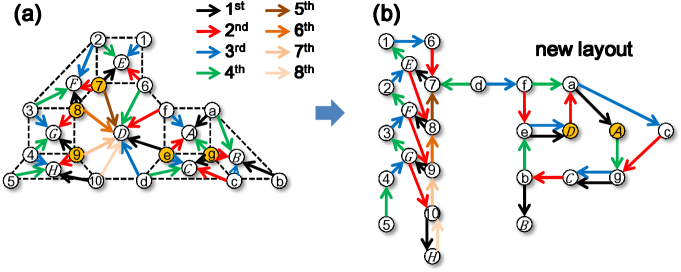
Let us show the effect of the replacement of CNOT gates by CNOT+SWAP gates in the 7-qubit color code, which is the minimum color code (code distance 3) Bombin ; Landahl . New connections between qubits are determined such that each step reproduces the same qubit states as those of Figs. 1(c) and 1(d). Figures 2(d) and 2(e) show the results of applying CNOT+SWAP gates, instead of CNOT gates, to the 7-qubit color code. This replacement transforms the qubit layout to a quasi-one-dimensional layout, where 2D access to all qubits is possible (Fig. 2(f)), and consequently no additional 3D layer for wiring is needed. Figure 2(e) is carried out after Fig. 2(d), where the order of CNOT+SWAP gates is reversed between Figs. 2(d) and 2(e). That is, we can use the same connections between the -checks and -checks, and syndrome measurements, in which the role of syndrome-qubits is shared in five qubits (qubits ‘A’, ‘B’, ‘C’, ‘a’ and ‘b’), can be repeated. The application of our method to the next larger code (code distance 5) also reduces the number of qubits that cannot be accessed two-dimensionally from 5 to 2 qubits as shown in Fig. 3.
So far, the stabilizer measurements have been assumed to be error-free. Otherwise, unexpected errors propagate through the stabilizer measurements for the color codes. The fault-tolerant version Gottesman2 of the 7-qubit code is described in Appendix.
IV Surface code
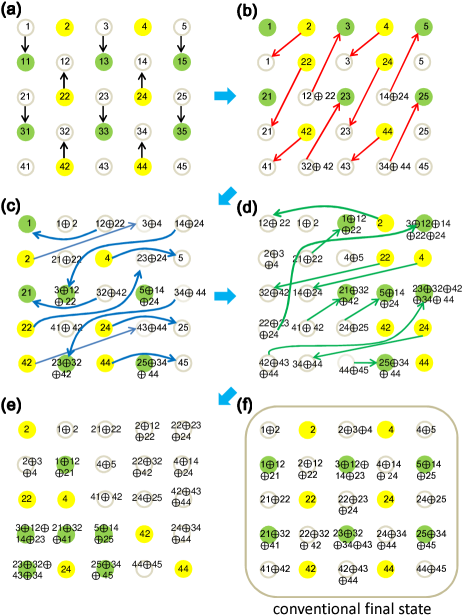
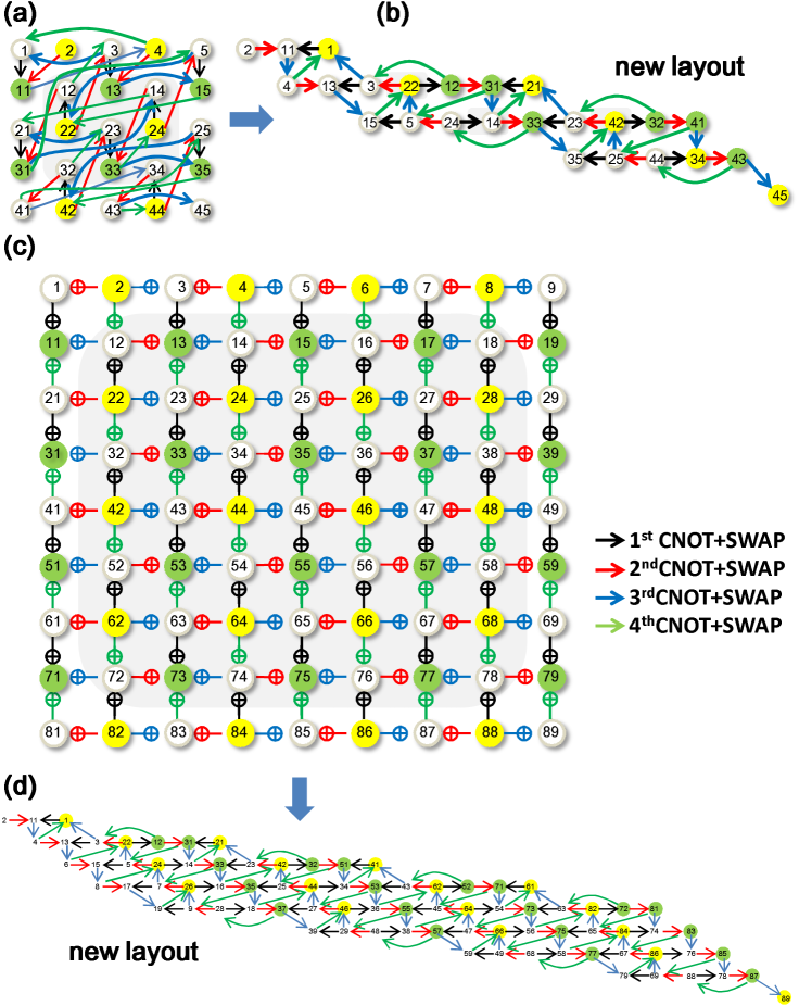
Next, we apply our idea to the standard surface code as shown in Fig. 4. In each step, the quantum state of Fig. 4 coincides with that of the standard state of Fig. 1(e). Figure 5(a) shows the new connections between qubits of a distance-3 surface code after the replacement of CNOT gates by CNOT+SWAP gates. When the connected qubits are rearranged closely, a new layout of qubits arises, as illustrated in Fig. 5(b), where 20 qubits share the role of the syndrome measurement. The number of the qubits to which two-dimensional access is impossible is reduced to three (qubits ‘14’, ‘22’ and ‘42’) from nine (=33 in Fig. 1(e)). Similarly, the number of the qubits that cannot be accessed two-dimensionally for a distance-5 surface code is reduced from 49 (=77) to 35 (=75), as shown in Fig 5(c) and Fig. 5(d), respectively. In general, the number of two-dimensionally inaccessible qubits for a distance- surface code is reduced from to by our method.
For distance- codes, a set of syndrome measurements is repeated more than times. The next processes of Figs. 5(b),(d) are carried out by reversing both the order of the connections and the directions of arrows. That is, the green connections are carried out first and the black one last, reversing the directions of the interactions. After the reversing process, the next connections are the same as Figs. 5(a),(c).
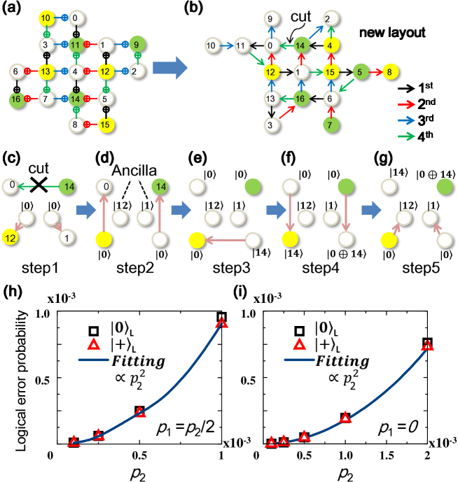
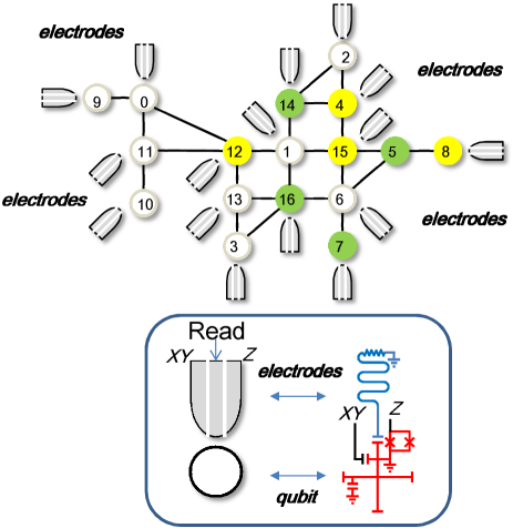
Rotated surface codes are known to be efficient surface codes Horsman . In the case of distance-3 surface codes, the number of qubits is reduced from 25 (Fig. 1(e)) to 17 (Fig. 6(a)). The order of operations is crucial for the fault-tolerance Tomita . Figure 6(b) shows the result of the replacement of CNOT gates by CNOT+SWAP gates. 12 qubits share the role of the syndrome measurements. Since the central qubit cannot be accessed two-dimensionally as before, we introduce a technique for cutting the connections, as a result of which a fully 2D layout is achieved. The cut technique is carried out by the additional five processes shown in Figs. 6(c)-(g) with ancilla qubits. (These operations are performed following the fourth time step shown in Fig. 6(b).) The ancilla qubits are initialized to states and used to hold the quantum states of the qubits ‘0’ and ‘14’. By serial application of CNOT+SWAP gates, the same operations as those without the cut can be realized. To demonstrate the usefulness of the cut technique, we evaluated the logical error probabilities of the distance-3 rotated surface code (Figs. 6(h),(i)) by numerical simulations Goto (see Appendix for details). The simulation results shown in Figs. 6(h) and (i) not only prove the fault-tolerance but also show substantial reduction of error probabilities. New rotated surface code layout with electrodes is shown in Fig. 7 where each electrode represents a set of wiring lines as used in Ref. Xmon1 ; Xmon2 .
V Conclusion
Replacement of CNOT gates by CNOT+SWAP gates which corresponds to iSWAP gates changes layouts of quantum error-correcting codes and relaxes the congestions of wiring between qubits. Importantly, we showed that fully 2D layouts including both qubits and control electrodes can be achieved for surface and color codes of minimum sizes. By the work-sharing, the concentration of workloads to specific qubits can be relaxed, and the degradation of the qubits will be mitigated. This will improve the reliability of a quantum circuit. Moreover, it is considered that simple 2D circuits are important for initial development phases of experiments. In general, it is not easy to operate circuits as expected, because some mistakes are often found in designs after fabrications. Thus, repeated fabrications of chips are necessary. Simple circuit layouts are beneficial for a reduction of fabrication period as well as fabrication process.
Acknowledgements.
We thank A. Nishiyama, M. Koyama, H. Hieda and S. Yasuda for discussions.Appendix A Simulation method.
To show the usefulness of the cut technique, we performed numerical simulations and evaluated the performance. Figure 4(h) shows the results where single-qubit error probabilities () are comparable to the two-qubit error probability () such as . Figure 4(i) shows the results where the single-qubit errors are rare compared to the two-qubit errors such as . Here, we assume that the two-qubit error is an error during a CNOT+SWAP operation. The curves in Figs. 4(h) and 4(i) are the fits to the simulation results with a function form of , where is a single fitting parameter. These excellent fits mean that any single-qubit errors have been corrected and therefore prove the fault tolerance of the syndrome measurements with the cut technique. It is also notable that the logical error probabilities are comparable to those in Ref. Tomita , where the cut technique is not used. Thus, we conclude that the cut technique is useful to realize fully accessible 2D layouts without spoiling performance.
In this simulation, we initially prepare error-free logical or and repeat syndrome measurements. In Fig. 6, the next process is carried out by reversing the order of the connections such that the cut is carried out first and the black one last. At the end of each round of syndrome measurements, we perform recovery operations according to the measurement results, where we estimate error positions with the lookup table decoder designed for the present case (see Tables 1-4). After the recovery, we estimate the logical error probabilities by error-free measurements and decoding the results. The error model assumed here is the standard depolarizing noise model: One of the three single-qubits Pauli errors occurs with probability on each idle qubit, after each initialization to and each Hadamard gate, and before each computational-basis measurement; one of the fifteen two-qubit Pauli errors occurs with probability after each CNOT+SWAP gate. For this simulation, we used the same stabilizer simulator as Ref. Goto . From the simulation results, we estimated logical error probabilities per round with the results of 40 rounds.
| Syndrome 1 | Syndrome 2 | Errors |
|---|---|---|
| 1 | 1 | |
| 2 | 2 | |
| 0 | 3 | |
| 1 | 3 | |
| 3 | 3 | |
| 4 | 4 | |
| 1 | 5 | |
| 0 | 6 | |
| 2 | 6 | |
| 6 | 6 | |
| 8 | 8 | |
| 2 | 10 | |
| 1 | 12 | |
| 4 | 12 | |
| 12 | 12 | |
| 0 | 13 |
Table 1: Lookup table for the -numbered round of -check. “Syndrome 1” and “Syndrome 2” columns show the penultimate and last rounds of syndrome measurements, respectively. The values in the columns are , where , , and are the computational-basis measurement results of the syndrome qubits initially placed at qubit 9, qubit 11, qubit 14, and qubit 16, respectively.
| Syndrome 1 | Syndrome 2 | Errors |
|---|---|---|
| 1 | 1 | |
| 2 | 2 | |
| 0 | 3 | |
| 2 | 3 | |
| 4 | 4 | |
| 4 | 5 | |
| 0 | 6 | |
| 4 | 6 | |
| 8 | 8 | |
| 8 | 10 | |
| 0 | 12 | |
| 8 | 12 | |
| 12 | 12 | |
| 12 | 13 |
Table 2 :Lookup table for the -numbered round of -check. The values in the columns are defined as in Table 1.
| Syndrome 1 | Syndrome 2 | Errors |
|---|---|---|
| 1 | 1 | |
| 2 | 2 | |
| 1 | 3 | |
| 4 | 4 | |
| 0 | 5 | |
| 1 | 5 | |
| 5 | 5 | |
| 0 | 6 | |
| 4 | 6 | |
| 6 | 6 | |
| 8 | 8 | |
| 0 | 10 | |
| 2 | 10 | |
| 10 | 10 | |
| 4 | 12 |
Table 3 :Lookup table for the -numbered round of -check. The values in the columns are , where , , and are the computational-basis measurement results of the syndrome qubits initially placed at qubit 10, qubit 12, qubit 13, and qubit 15, respectively.
| Syndrome 1 | Syndrome 2 | Errors |
|---|---|---|
| 1 | 1 | |
| 2 | 2 | |
| 2 | 3 | |
| 4 | 4 | |
| 0 | 5 | |
| 4 | 5 | |
| 0 | 6 | |
| 2 | 6 | |
| 8 | 8 | |
| 0 | 10 | |
| 8 | 10 | |
| 8 | 12 |
Table 4: Lookup table for the -numbered round of -check. The values in the columns are defined as in Table 3.
Appendix B Fault-tolerant 7-qubit code.
One way to meet the condition of fault tolerance Nielsen is to use cat states in the stabilizer measurements Shor . Figure 8(a) shows a direct application of the four-qubit cat-state to the color code in Z-check. (Creation of the cat state is described in Fig. 9.) The connections between qubits change when it is compared with Fig. 2(d) in the text, because at most four data-qubits can access the cat state simultaneously. Note that the connections A4-A3-B4-C1-C4-A4 constitute a closed loop, and consequently the qubit ‘g’ cannot be accessed in the same physical plane.
By cutting the connection between ‘A4’ and ‘C4’, we can realize the fault-tolerant 7-qubit color code where all qubits can be accessed two-dimensionally. Three ancilla qubits that interact with the qubits ‘A3’, ‘B4’, ‘C1’ are introduced to store the quantum states of those qubits. The interaction between ‘A4’ and ‘C4’ with the cut technique is carried out by connecting qubit pairs among ‘A3’, ‘B4’, and ‘C1’ one by one. Additional 11 steps are required (see Fig. 10).
References
- (1) T. Yamamoto, Y.A. Pashkin, O. Astafiev, Y. Nakamura, and J.S. Tsai, Nature 425, 941 (2003).
- (2) A.O. Niskanen, K. Harrabi, F. Yoshihara, Y. Nakamura, S. Lloyd, and J.S. Tsai, Science, 316, 723 (2007).
- (3) J.H. Plantenberg, P.C. de Groot, C.J. Harmans, and J.E. Mooij, Nature 447, 836 (2007).
- (4) A. Wallraff, D.I. Schuster, A. Blais, L. Frunzio, R.S. Huang, J. Majer, S. Kumar, S.M. Girvin, and R.J. Schoelkopf, Nature 431, 162 (2004).
- (5) R. Barends, J. Kelly, A. Megrant, D. Sank, E. Jeffrey, Y. Chen, Y. Yin, B. Chiaro, J. Mutus, C. Neill, P . ÓMalley, P. Roushan, J. Wenner, T.C. White, A.N. Cleland, and J.M. Martinis, Phys. Rev. Lett. 111, 080502 (2013).
- (6) R. Barends, J. Kelly, A. Megrant, A. Veitia, D. Sank, E. Jeffrey, T.C. White, J. Mutus, A.G. Fowler, B. Campbell, Y. Chen, Z. Chen, B. Chiaro, A. Dunsworth, C. Neill, P. ÓMalley, P. Roushan, A. Vainsencher, J. Wenner, A.N. Korotkov, A. N. Cleland, and J.M. Martinis, Nature 508, 500 (2014).
- (7) T.D Ladd, F. Jelezko, R. Laflamme, Y. Nakamura, C. Monroe, and J.L. ÓBrien, Nature 464, 45 (2010).
- (8) R.J. Schoelkopf and S.M. Girvin,Nature 451, 664 (2008).
- (9) D. Ristè, S. Poletto, M.Z. Huang, A. Bruno, V. Vesterinen, O.P. Saira, and L. DiCarlo, Nat. Commun. 6, 6983 (2015).
- (10) J. Kelly, R. Barends, A.G. Fowler, A. Megrant, E. Jeffrey, T.C. White, D. Sank, J.Y. Mutus, B. Campbell, Yu Chen, Z. Chen, B. Chiaro, A. Dunsworth, I.C. Hoi, C. Neill, P. J. J. ÓMalley, C. Quintana, P. Roushan, A. Vainsencher, J. Wenner, A.N. Cleland, and J.M. Martinis, Nature 519, 66 (2015).
- (11) A.D. Córcoles, E. Magesan, S.J. Srinivasan, A.W. Cross, M. Steffen, J.M. Gambetta, and J.M. Chow, Nat. Commun. 6, 6979 (2015).
- (12) S.B. Bravyi and A.Y. Kitaev, arXiv:quant-ph/9811052.
- (13) E. Dennis, A. Kitaev, Y.A. Landahl, and J. Preskill, J. Math.Phys.43, 4452 (2002).
- (14) A.G. Fowler, M. Mariantoni, J.M. Martinis, and A.N. Cleland, Phys. Rev. A 86, 032324 (2012).
- (15) A.G. Fowler, A.C. Whiteside, A.L. McInnes, and A. Rabbani, Phys. Rev. X 2 041003 (2012).
- (16) C.D. Hill, E. Peretz, S.J. Hile, M.G. House, M. Fuechsle, S. Rogge, M.Y. Simmons, and L.C.L. Hollenberg, Sci. Adv.1, e1500707 (2015).
- (17) S.J. Devitt, Phys. Rev. A 94, 032329 (2016).
- (18) H. Bombin and M.A. Martin-Delgado, Phys. Rev. Lett. 97, 180501 (2006).
- (19) A.J. Landahl, J.T. Anderson, and P.R. Rice, arXiv:1108.5738.
- (20) C. Jones, P. Brooks, and J. Harrington, Phys. Rev. A 93, 052332 (2016).
- (21) D. Nigg, M. Mueller, E. A. Martinez, P. Schindler, M. Hennrich, T. Monz, M.A. Martin-Delgado, and R. Blatt, Science 345, 302 (2014).
- (22) T. Brecht, W. Pfaff, C. Wang, Y. Chu, L. Frunzio, M.H. Devoret, and R.J. Schoelkopf, npj Quantum Information 2 16002 (2016).
- (23) T. Lanting, A.J. Przybysz, A.Y. Smirnov, F.M. Spedalieri, M.H Amin, A.J. Berkley, R. Harris, F. Altomare, S. Boixo, P. Bunyk, N. Dickson, C. Enderud, J.P. Hilton, E. Hoskinson, M.W. Johnson, E. Ladizinsky, N. Ladizinsky, R. Neufeld, T. Oh, I. Perminov, C. Rich, M.C. Thom, E. Tolkacheva, S. Uchaikin, A.B. Wilson and G. Rose, Phys. Rev. X 4, 021041 (2014).
- (24) M.A. Nielsen and I.L. Chuang, Quantum Computation and Quantum Information (Cambridge Univ. Press, 2000).
- (25) D. Gottesman, quant-ph/9705052.
- (26) D.P. DiVincenzo, D. Bacon, J. Kempe, G. Burkard, and K.B. Whaley, Nature 408, 339 (2000).
- (27) K.M. Svore, B.M. Terhal, and D.P. DiVincenzo, Phys. Rev. A 72, 022317 (2005).
- (28) The model is expressed by the Hamiltonian where are the Pauli matrices acting on the -th qubit with basis and . The iSWAP operation acting on qubits ‘1’ and ‘2’ is given by such as , , , and
- (29) N. Schuch and J. Siewert, Phys. Rev. A 67, 032301 (2003).
- (30) T. Tanamoto, Y.X. Liu, X. Hu, and F. Nori, Phys. Rev. Lett. 102, 100501 (2009).
- (31) T. Tanamoto, K. Maruyama, Y.X. Liu, X. Hu, and F. Nori, Phys. Rev. A 78, 062313 (2008).
- (32) L.F. Wei, J.R. Johansson, L.X. Cen, S. Ashhab, and F. Nori, Phys. Rev. Lett. 100, 113601 (2008).
- (33) R.C. Bialczak, M. Ansmann, M. Hofheinz, E. Lucero, M. Neeley, A.D. ÓConnell, D. Sank, H. Wang, J. Wenner, M. Steffen, A.N. Cleland, and J.M. Martinis, Nat. Phys 6, 409 (2010).
- (34) A. Dewes, F.R. Ong, V. Schmitt, R. Lauro, N. Boulant, P. Bertet, D. Vion, and D. Esteve, Phys. Rev. Lett. 108, 057002 (2012).
- (35) D.C. McKay, S. Filipp, A. Mezzacapo, E. Magesan, J.M. Chow, and J.M. Gambetta, arXiv:1604.03076.
- (36) D. Gottesman, Proc. Sympos. Appl. Math 68, 13 (2010).
- (37) C. Horsman, A.G. Fowler, S. Devitt, and R. Van Meter, New J. Phys.14, 123011 (2012).
- (38) Y. Tomita and K.M. Svore, Phys. Rev. A 90, 062320 (2014).
- (39) H. Goto and H. Uchikawa, Sci. Rep. 3, 2044 (2013).
- (40) P.W. Shor, quant-ph/9605011.