Optically driven ultra-stable nanomechanical rotor
Abstract
Nanomechanical devices have attracted the interest of a growing interdisciplinary research community, since they can be used as highly sensitive transducers for various physical quantities. Exquisite control over these systems facilitates experiments on the foundations of physics. Here, we demonstrate that an optically trapped silicon nanorod, set into rotation at MHz frequencies, can be locked to an external clock, transducing the properties of the time standard to the rod’s motion with the remarkable frequency stability of . While the dynamics of this periodically driven rotor generally can be chaotic, we derive and verify that stable limit cycles exist over a surprisingly wide parameter range. This robustness should enable, in principle, measurements of external torques with sensitivities better than 0.25 zNm, even at room temperature. We show that in a dilute gas, real-time phase measurements on the locked nanorod transduce pressure values with a sensitivity of 0.3 %.
Introduction
Frequency is the most precisely measured quantity in physics, and stable oscillators have found a plethora of applications in metrology. While pendulum clocks exploited the stability of mechanical motion to keep track of time, state-of-the-art atomic clocks rely on well-defined internal resonances of atoms, achieving a precision of a few parts in Ludlow2015 . To exploit the stability of clocks for physical applications, it is essential to develop “gearboxes” that can be synchronized to a good time standard, translating atomic definiteness into other domains of physics. Phase-locked quartz oscillators Vig1999 and frequency combs are examples of such transducers, imprinting clock stability onto a mechanical system or light field respectively, with high accuracy Udem2002 .
Nano- and micromechanical systems are of great technological interest, due to their low mass and extreme sensitivity to external forces Rugar01 ; Kippenberg12 ; Geraci15 , torques Kim13 ; Kim16 , acceleration Painter12 , displacement Lehnert09 ; Wilson15 , charge Roukes98 , and added mass Bachtold12 ; Zadeh13 . Many of these systems are themselves realizations of harmonic oscillators, with frequency stabilities reaching Norte16 ; Schliesser16 , which can be further improved through mechanical engineering Ghaffari14 , injection locking Vahala08 ; Coppock16 , electronic feedback Roukes08 , or parametric driving Villanueva11 . The contact-free mechanical motion of particles suspended by external fields in vacuum Twamley12 ; Gieseler12 ; Yin13 ; Kiesel13 ; Vamivakas14 ; Millen15 ; Hoang2016 ; Kuhn16 , can reach a frequency stability that is only limited by laser power fluctuations and collisional damping by residual gas particles Chang10 .
In this work, we transduce clock stability into the rotation of an optically trapped silicon nanorod in vacuum. By periodically driving the rotation with circularly polarized light, we create a nanomechanical rotor whose rotation frequency , and frequency noise, is determined by the periodic drive alone. This driven rotor is sensitive to non-conservative forces, and the operating frequency can be tuned by almost times its linewidth. Through our method, the frequency stability is independent of material stress, laser noise, and collisional damping. The driven nanorotor operates at room temperature, and across a wide pressure range from low vacuum to medium vacuum, achieving a pressure resolution of 3 parts-per-thousand, and in principle allowing a torque sensitivity below the zepto-Nm level.
Results
Frequency locking
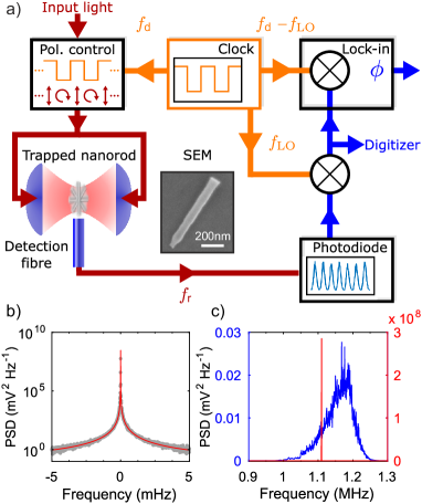
We levitate a nanofabricated silicon nanorod in the standing light wave formed by two counterpropagating laser beams, and track its motion by monitoring the scattered light, see Fig.1a and Methods. When the laser is linearly polarized, the nanorod is harmonically trapped in an antinode of the standing wave and aligned with the field polarization. When the laser is circularly polarized, the scattered light exerts a torque Tong09 ; Dholakia13 ; Kuhn16 and propels the nanorod in the plane orthogonal to the beam axis, while its centre-of-mass remains trapped Kuhn16 . The maximum rotation frequency of the rod is determined by its size, the pressure, and the laser intensity Kuhn16 . Collisions with gas particles, and centre-of-mass excursions into regions of different light intensity, give rise to a broad distribution of rotational frequencies Kuhn16 , as shown by the blue curve in Fig. 1c.
However, if the rod is driven by periodically switching the laser polarization between linear and circular, the rod can frequency-lock to this modulation, leading to a sharp peak in the power spectral density (PSD) of the scattered light (Fig. 1b). The locked rotation peak is eleven orders of magnitude narrower than in the unlocked case (see Fig.1c). The rotation frequency can be continuously tuned over a range of linewidths whilst locked to the periodic drive, retaining its high frequency stability.
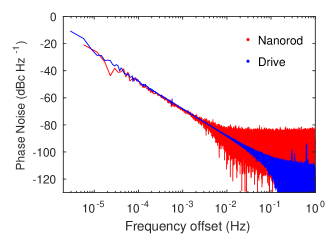
In order to characterize the frequency-locked rotation, we drive the nanorod with frequency MHz, at a gas pressure mbar and total laser power W. We record its motion continuously for four days (see Methods section). The PSD of the locked rotation is shown in Fig. 1b. We record an extremely narrow feature, which yields a Lorentzian FWHM below Hz within one standard deviation. In this way, we achieve rotational stability with a phase noise dBc Hz-1 below the signal at only mHz from the carrier frequency (Fig. 2).
Stable limit cycles
To explain this ultra-stable rotation, we model the dynamics of the rod’s orientation with respect to the polarization axis Kuhn16 . Denoting by the damping rate due to gas collisions (a function of gas pressure ), by the torque exerted by the circularly polarized standing wave (a function of laser power ) and by the maximum potential energy of the rod in a linearly polarized standing wave, the equation of motion is
| (1) |
where is the moment of inertia and represents the periodic driving, with for circular polarization at and for linear polarization at ; expressions for , , and are given in the Methods section.
In the limit of long driving times the nanorod rotates with constant mean rotation frequency , and its motion approaches one of two qualitatively distinct types of limit cycle. In the first type, threshold rotation, is determined by the balance between and the time averaged radiation torque . Threshold rotation exhibits a broad frequency distribution, as shown by the blue curve in Fig. 1c, due to its dependence on and Kuhn16 . It should be noted, that the behaviour of threshold rotation is almost identical to illuminating the nanorotor continuously with circularly polarized light, which propels the rod at a maximum rotation frequency .
In the second type of limit cycle, the aforementioned locked rotation, locks to a rational fraction of the driving frequency. Experimentally, we observe - and - locking, where the rod performs one rotation in two or four driving periods, respectively. The rotational frequency now does not depend on environmental parameters such as or , but only on the frequency stability of the drive. Locked rotation is shown in Fig. 1b and the red curve in Fig. 1c.
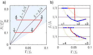
The realized limit cycle is determined by the initial dynamics of the nanorod, and by experimental parameters such as , and the rod dimensions. For a given nanorod the ratio between torque and potential is fixed, and thus Eq. (1) depends only on the dimensionless damping rate and dimensionless torque . In Fig. 3a we show this reduced parameter space. The blue shaded area indicates the region where - locking is possible. The labelled solid lines indicate where threshold and locked rotations have the same frequency, and locking occurs independent of the initial conditions.
Rotational dynamics
To explore the dynamics of the driven nanorotor, we experimentally vary and , thereby following a path through parameter space (red line in Fig. 3a). The observed are shown as blue points in Fig. 3b, the top panel showing the path 1-2-3, and the lower panel 3-4. This plot shows that for certain parameters both types of limit cycles can be observed, depending on the initial conditions. When starting from 1, the rotation - locks to the drive (horizontal solid line). When increasing along 1-2, the rod jumps out of lock, and exhibits threshold rotation. When decreasing along 2-3, the rod remains at threshold rotation, following the theoretically expected frequencies with excellent agreement (orange dotted lines). Decreasing along 3-4, the rod first follows the threshold rotation frequency until it crosses the horizontal line, where it briefly enters - locked rotation, returns to threshold rotation and eventually jumps into - locked rotation. The solid red lines in Fig. 3b are the theoretically predicted for an adiabatic path through parameter space, with the discrepancy due to imperfect adiabatic control in the experiment.
Applications
For - locked rotation, the phase lag between the drive and the rotation is
| (2) |
it depends upon gas pressure through and on laser power through and . The requirement that this phase is real defines the shaded region in Fig. 3a. The phase is sensitive to non-conservative forces, such as light or gas scattering.
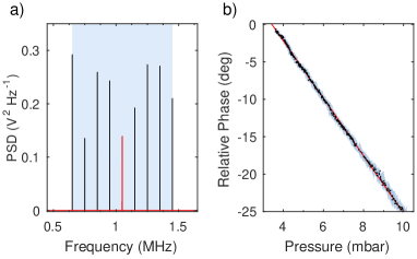
A lock-in amplifier is used to monitor (see the Methods section), yielding real-time readout of phase variations. For a constant laser power , measuring the phase amounts to local sensing of the gas pressure , as shown in Fig. 4b. We achieve a relative pressure sensitivity of %, which is currently limited only by the intensity noise of the fiber amplifier. This sensitivity may still be improved by five to six orders of magnitude by stabilizing the power Kwee11 . This shows the great potential of our system as a pressure sensor. The fine spatial resolution provided by the micrometer-sized rotor could allow, for instance, mapping of velocity fields and turbulences in rarefied gas flows or atomic beams.
The driven nanorod is sensitive to externally applied torques through Eq. (1). In analogy to the pressure sensing application, the phase between the drive and the driven rotation of the locked rotor provides a real-time readout with a bandwidth of 100 kHz set by the lock-in amplifier. From Eq. (2), the torque sensitivity can be estimated as Nm for our current experimental parameters, which at room temperature would be the highest value achieved in state of the art systems Kim16 , and which could also be significantly improved by laser power stabilization. This sensitivity can be reached for any non-conservative force, that varies on a timescale longer than . The bandwidth and sensitivity of this sensor for arbitrary torques warrants further investigation.
Discussion
In conclusion, we have presented a technique for locking the rotation of a levitated nanomechanical rotor to a stable frequency reference, leading to a high mechanical frequency stability which can be used for instantaneous, highly sensitive local measurements of pressure or torque. One great advantage of the locked nanorotor over nanomechanical resonators is the absence of an intrinsic resonance frequency. By varying we can tune the rotation frequency over almost linewidths while retaining its stability, as shown in Fig. 4a, circumventing the low bandwidth that naturally comes with highly sensitive resonant detectors. Measuring a phase lag rather than a frequency shift allows us to monitor force variations in real time, bypassing the inherent growth in measurement time that comes with decreasing linewidth in a resonant sensor.
Our system is sensitive to non-conservative forces, such as those due to photon absorption or emission, shear forces in gas flows, radiation pressures in light fields, optical potentials, mass and size variations of the rod due to gas accommodation, and local pressure and temperature variations in the gas. Employing higher optical powers, larger duty cycles of the drive, or lower gas pressures will increase the sensing range by a factor of more than ten, while retaining the exquisite sensitivity. The stability of the locked nanorotor may be further increased by driving it with a more stable clock. By reaching ultra high vacuum, this technique may also be suited to prepare quantum coherent rotational dynamics Bhattacharya16 , for which the high frequency stability may be exploited.
Methods
Nanorod trapping
A silicon nanorod of length nm and diameter nm (with mass kg) is trapped at a pressure of mbar, using light of total power W with RMS power fluctuations of 0.3 %. Our method of producing and trapping the nanorods is described in Refs. Kuhn15 ; Kuhn16 . The motion is monitored by placing a 1 mm core multimode fibre less than m from the trapped nanorod, which collects the light that the nanoparticle scatters, yielding information about all translational and rotational degrees of freedom.
Rotation analysis
In order to record a time series as long as 4 days we mix down the scattered light with a local oscillator at frequency such that the rotational motion signal of the rod is shifted to a frequency of 190 Hz (see Fig. 1a) and digitized with a sampling rate of kS s-1. This signal can then be used to calculate the phase noise in units of dBc Hz-1. The drive signal is recorded and analysed in the same way.
To extract the relative phase of the nanorod rotation with respect to the drive we use a Stanford Research Systems lock-in amplifier (SR830) which performs a homodyne measurement on the mixed-down 190 Hz scattering signal. For this purpose both the modulation frequency and the local oscillator are synced to a common clock.
Rotational dynamics
The rotational motion depends crucially on the damping rate , the radiation torque , and the laser potential , through Eq. (1). All three quantities can be evaluated microscopically as detailed in Refs. Kuhn16 ; Stickler16 . Specifically, the rotational damping rate due to diffuse reflection of gas atoms with mass , evaluated in the free molecular regime, is , where denotes the gas temperature. The optical torque exerted by a circularly polarized standing wave can be evaluated by approximating the internal polarization field according to the generalized Rayleigh-Gans approximation Stickler16 as , where is the wavenumber, depends on the two independent components of the susceptibility tensor and and Kuhn16 . In a similar fashion, one obtains for the laser potential .
The phase lag (2) is obtained by averaging the equation of motion (1) over one driving period and exploiting that the motion is 1:2-locked, while and, consequently, . The phase difference between the polarization change from circular to linear and the maximum scattering signal observed when the rod is oriented orthogonal to the detector () is leading to Eq. (2).
Data Availability
All relevant data are available from the corresponding author upon request.
References
- (1) Ludlow, A. D., Boyd, M. M., Ye, J., Peik, E. and Schmidt, P. O., “Optical atomic clocks.” Rev. Mod. Phys. 87, 637-701 (2015).
- (2) Vig, J. R., “Quartz crystal oscillators and resonators‘.” Technical Report No. SLCET-TR-88-1, Army Research Laboratory, (1999).
- (3) Udem, Th., Holzwarth, R., Hänsch, T. W., “Optical frequency metrology.”, Nature 416, 233-237 (2002).
- (4) Mamin, H. J. and Rugar, D., “Sub-attonewton force detection at millikelvin temperatures.” Appl. Phys. Lett. 79, 3358-3360 (2001).
- (5) Gavartin, E., Verlot, P. and Kippenberg, T. J., “A hybrid on-chip optomechanical transducer for ultrasensitive force measurements.” Nature Nanotech. 7, 509-514 (2012).
- (6) Ranjit, G., Atherton, D. P., Stutz, J. H., Cunningham, M. and Geraci, A. A., “Attonewton force detection using microspheres in a dual-beam optical trap in high vacuum.” Phys. Rev. A 91, 051805 (2015).
- (7) Kim, P. H. et al., “Nanoscale torsional optomechanics.” Appl. Phys. Lett. 102, 053102 (2013 ).
- (8) Kim, P. H., Hauer, B. D., Doolin, C., Souris, F. and Davis, J. P., “Approaching the standard quantum limit of mechanical torque sensing.” Nature Communs. 7, 13165 (2016).
- (9) Krause, A. G., Winger, M., Blasius, T. D., Lin, Q. and Painter, O., “A high-resolution microchip optomechanical accelerometer.” Nature Photonics 6, 768-772 (2012).
- (10) Teufel, J. D., Donner, T., Castellanos-Beltran, M. A., Harlow, J. W. and Lehnert, K. W., “Nanomechanical motion measured with an imprecision below that at the standard quantum limit.” Nature Nanotech. 4, 820-823 (2009).
- (11) Wilson, D. J. et al., “Measurement-based control of a mechanical oscillator at its thermal decoherence rate.” Nature 524, 325-329 (2015).
- (12) Cleland, A. and Roukes, M., “A nanometre-scale mechanical electrometer.” Nature 392, 160-162 (1998).
- (13) Chaste, J., Eichler, A., Moser, J., Ceballos, G., Rurali. R and Bachtold, A., “A nanomechanical mass sensor with yoctogram resolution.” Nature Nanotech. 7, 301-304 (2012).
- (14) Liu, F., Alaie, S., Leseman, Z. C. and Hossein-Zadeh, M., “Sub-pg mass sensing and measurement with an optomechanical oscillator.” Optics Express 21, 19555-19567 (2013).
- (15) Norte, R. A., Moura, J. P., Gröblacher, S., “Mechanical Resonators for Quantum Optomechanics Experiments at Room Temperature.” Phys. Rev. Lett. 116, 147202 (2016).
- (16) Tsaturyan, Y., Barg, A., Polzik, E. S. and Schliesser, A., “Ultra-coherent nanomechanical resonators via soft clamping and dissipation dilution.” Nature Nanotech. 12, 776-783 (2017).
- (17) Ghaffari, S. et al., “Quantum Limit of Quality Factor in Silicon Micro and Nano Mechanical Resonators.” Sci. Rep. 3, 3244 (2014).
- (18) Hossein-Zadeh, M. and Vahala, K. J., “Observation of injection locking in an optomechanical rf oscillator.” Appl. Phys. Lett. 93, 191115 (2008).
- (19) Coppock, J. E., Nagornykh, P., Murphy, J. P. J. and Kane, B. E., “Phase locking of the rotation of a graphene nanoplatelet to an RF electric field in a quadrupole ion trap.” Proc. SPIE 9922, Optical Trapping and Optical Micromanipulation XIII, 99220E (2016).
- (20) Feng, X. L., White, C. J., Hajimiri, A. and Roukes, M. L., “A self-sustaining ultrahigh-frequency nanoelectromechanical oscillator.” Nature Nanotech. 3, 342-346 (2008).
- (21) Villanueva, L. G. et al., “A Nanoscale Parametric Feedback Oscillator.” Nano Lett. 11, 5054-5059 (2011).
- (22) Cirio, M., Brennen, G. K. and Twamley, J., “Quantum Magnetomechanics: Ultrahigh-Q-Levitated Mechanical Oscillators.” Phys. Rev. Lett. 109, 147206 (2012)
- (23) Gieseler, J., Deutsch, B., Quidant, R. and Novotny, L., “Subkelvin Parametric Feedback Cooling of a Laser-Trapped Nanoparticle.” Phys. Rev. Lett. 109, 103603 (2012).
- (24) Yin, Z.-Q., Geraci, A. A. and Li, T., “Optomechanics of levitated dielectric particles.” Int. J. Mod. Phys. B 27, 1330018 (2013).
- (25) Kiesel, N. et al., “Cavity cooling of an optically levitated submicron particle.” Proc. Natl. Acad. Sci. USA 110, 14180-14185 (2013).
- (26) Neukirch, L. P. and Vamivakas, A. N., “Nano-optomechanics with optically levitated nanoparticles.” Contemp. Phys. 56, 48-62 (2014).
- (27) Millen J., Fonseca, P. Z. G., Mavrogordatos, T., Monteiro, T. S. and Barker, P. F., “Cavity Cooling a Single Charged Levitated Nanosphere” Phys. Rev. Lett. 114, 123602 (2015).
- (28) Hoang, T. M. et al., “Torsional Optomechanics of a Levitated Nonspherical Nanoparticle.” Phys. Rev. Lett. 117, 123604 (2016)
- (29) Kuhn, S. et al., “Full Rotational Control of Levitated Silicon Nanorods.” Optica (2016) 4, 356-360 (2017).
- (30) Chang, D. E. et al., “Cavity opto-mechanics using an optically levitated nanosphere.” Proc. Natl. Acad. Sci. USA 107, 1005-1010 (2010).
- (31) Tong, L., Miljković, V. D. and Käll, M., “Alignment, Rotation, and Spinning of Single Plasmonic Nanoparticles and Nanowires Using Polarization Dependent Optical Forces.” Nano Lett. 10, 268-273 (2009).
- (32) Arita, Y., Mazilu, M. and Dholakia, K., “Laser-induced rotation and cooling of a trapped microgyroscope in vacuum.” Nature Communs. 4, 2374 (2013).
- (33) Kwee, P., Willke, B. and Danzmann, K., “New concepts and results in laser power stabilization.” Appl. Phys. B 102, 515-522 (2011)
- (34) Shi, H. and Bhattacharya, M., “Optomechanics based on angular momentum exchange between light and matter.” J. Phys. B: At. Mol. Opt. Phys. 49, 153001 (2016).
- (35) Kuhn, S. et al., “Cavity-Assisted Manipulation of Freely Rotating Silicon Nanorods in High Vacuum.” Nano Lett. 15, 5604-5608 (2015).
- (36) Stickler, B. A. et al., “Ro-Translational Cavity Cooling of Dielectric Rods and Disks.” Phys. Rev. A 94, 033818 (2016)
Acknowledgments
We are grateful for financial support by the Austrian Science Fund (FWF) in the projects P27297 and DK-CoQuS (W1210). We acknowledge support by S. Puchegger and the faculty center for nanostructure research at the University of Vienna in imaging the nanorods. JM acknowledges funding from the European Union’s Horizon 2020 research and innovation programme under the Marie Skłodowska-Curie grant agreement No 654532. F.P. acknowledges the Legacy Program (Israel Science Foundation) for its support.
Author Contributions
S.K., M.A. and J.M. conceived of and designed the experiment. S.K. and J.M. performed all experiments. S.K., B.A.S. and J.M. analysed the data. A.K. and F.P. fabricated the nanorods. B.A.S. and K.H. developed all theoretical models. S.K., B.A.S., K.H., M.A. and J.M. contributed to the writing of the manuscript.
Competing Financial Interests
Aspects of this work are subject to a filed patent application.