Directional radiation of sound waves by a subwavelength source
Abstract
We propose and experimentally achieve a directional dipole field radiated by an omnidirectional monopole source enclosed in a subwavelength structure of acoustically hybrid resonances. The whole structure has its every dimension at an order smaller than the sound wavelength. The significance is that the radiation efficiency is up to 2.3 of the radiation by traditional dipole consisting of two out-of-phase monopoles in the same space. This study eventually takes an essential step towards solving the long-existing barrier of inefficient radiation of directional sound waves in low frequencies, and consequently inspires the ultimate radiation of arbitrary multipoles or even a highly directional beam by a monopole in limited spaces.
pacs:
XXDirectional radiation of sound waves is of fundamental interest to the field of acoustics, with obvious potential to revolutionize various applications, such as focused sound waves for imaging, directional sound beams for underwater communication, among others. Yet in practice, from a classical perspective, any sound source with dimensions much smaller than the wavelength will act as a monopole and always radiate sound energy equally in all directions while the multipole radiation is inefficient relevant to the monopoleC. and U. (1968); Russell et al. (1999). To compensate the source size limitation, directional radiated fields at low frequency have to be produced via arrays of sourcesLi et al. (2015) or sources that must move by long distance to synthesize a large-scale aperture in order for a source dimension comparable to the wavelengthBerkhout et al. (2016); Azar et al. (2000); Wang (1992); S. and A. (1989); C. et al. (1999). This poses a fundamental barrier on radiation of directional sound waves at low frequencies by a finite-size source, therefore preventing the effective downscaling of acoustic devices. We pursue radiation of low-frequency directional sound waves by a subwavelength source.
Many mechanisms have already been developed for controlling low-frequency sound radiation, which usually depend on coiling up space structures that force the sound to travel through a zigzag path to delay its propagation phaseZhao et al. (2013); Li et al. (2014); Liang and Li (2012); Zhu et al. (2016), or some hybrid resonant structures that use arrays of resonators to accumulate a sufficient phase lagC. et al. (1999); Li et al. (2015). The existing metastructures based on these mechanisms, despite their vanishing thickness, still need to have a large transverse dimension in terms of wavelength to form a directional beam. On the other hand, metamaterials with anisotropic parameters designed by coordinate transformation technique can rotate the omni-directivity of a sound field but is still not able to reshape the directivity in subwavelength dimensionJiang et al. (2016). Instead, we seek to develop a structure enclosing a monopole that as a whole has a subwavelength dimension yet can radiate directional sound waves at low frequency.
This letter takes the first step for breaking through the barrier to enable a high efficient production of a dipolar field from a deep-subwavelength structure wrapping around a simple point source. To elucidate our mechanism underlying such unusual phenomenon, we begin with a revisit of the sound field radiated from a finite-size source of a volume , , where is the Green’s function of free space with being the wave numberC. and U. (1968). By taking the multipole expansion around the source center ,
| (1) |
where the first term is the monopole term, while the second term represents the dipole radiation with the factor in the far field form as
| (2) |
For a low-frequency airborne sound radiated in free space, one has while radiated from a source of a small volume with ( is the wavelength), and hence the dipole part would be trivial as compared to the monopole part, in accordance with the conventional notion that any source with subwavelength dimension always behaves like a monopole with omni-directional radiation. A directional radiation of low-frequency sound, as a consequence, has to depend on a sufficiently large in terms of wavelength, which is realized by arranging small sources into an array with dimension comparable with wavelengthLi et al. (2015) or by synthesizing a large-scale aperture with moving sources, as done in traditional methods.Berkhout et al. (2016); Azar et al. (2000); Wang (1992); S. and A. (1989); C. et al. (1999)
Here we achieve the radiation of a dipole field from a monopole source enclosed by a proposed structure with deep-subwavelength dimension, based on an essentially different mechanism that manipulates the effective wave number instead of enlarging the dimension of source for achieving a large . We substantially expand the effective wave number to make , thereby satisfying the basic requirement that the wavelength and the source dimension must be comparable. We demonstrate this mechanism both numerically and experimentally by converting a monopole into a dipole with near-unity efficiency with a deep-subwavelength structure.
Model
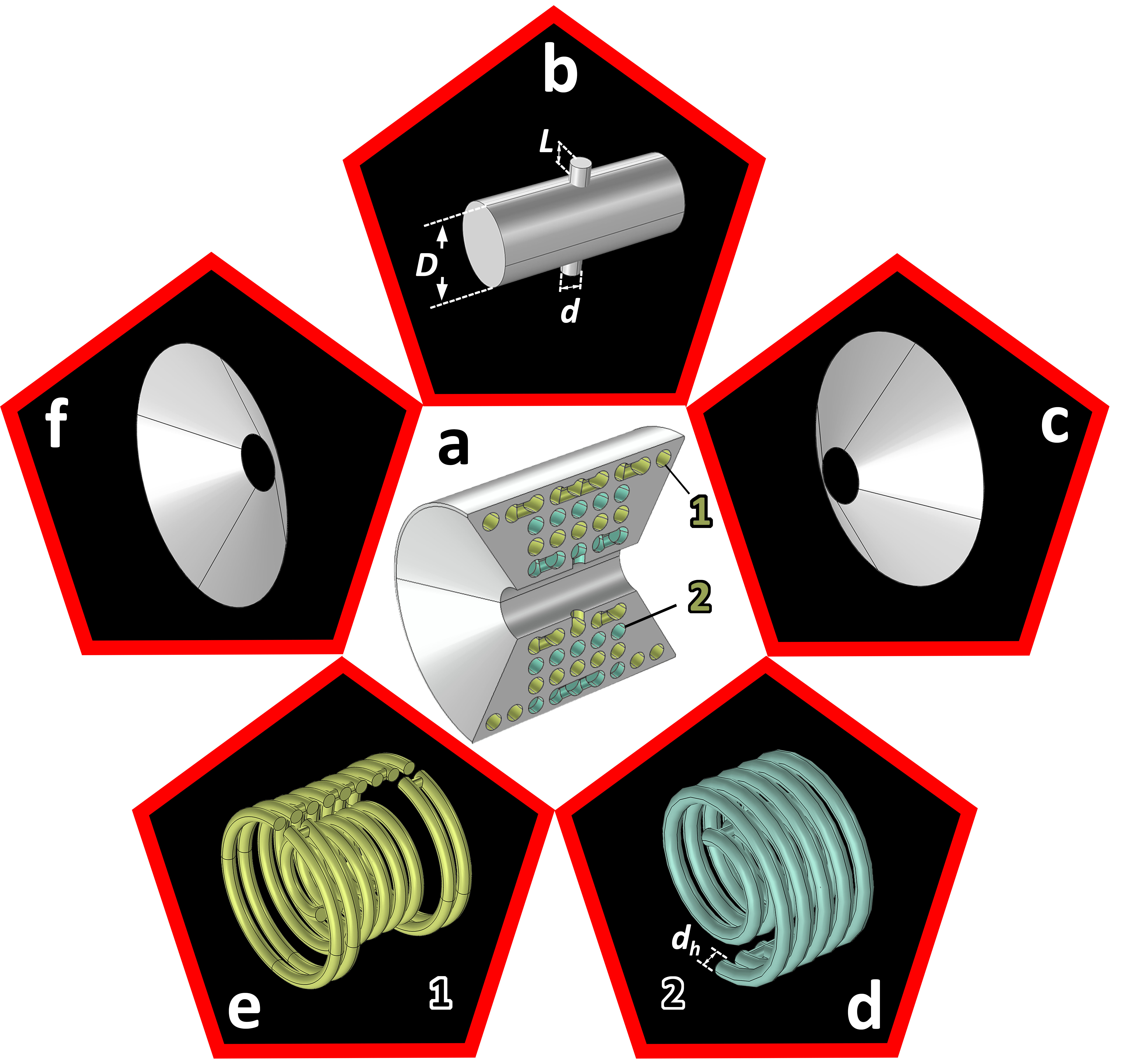
The artificial structure to implement our distinctive idea, shown in Fig.1(a), is formed by coupling a straight cylindrical tube of constant cross-sectional area shown in Fig.1(b) with two facing spiral tubes shown in Fig.1(d) and (e). The two facing tubes, spirally wrapped around the straight tube with their openings being attached at two opposite openings in the middle of that tube, maximally compress the dimension of the resulting device. And the two parts shown in Fig.1(c) and (f) are connected to the straight cylindrical tube on the both ends to optimize the radiation by improving the impedance matching. While guaranteeing the deep subwavelength scale of the overall size of the whole structure, the combination of straight and spiral tubes supports hybrid internal resonances that substantially slow down the transmission wave and change the effective wave number to make , as will be proven in what follows.
Consider the sound field radiated from a simple monopole source located at one end of the straight tube shown in Fig.1(b). With a cross-sectional dimension much smaller than the driving wavelength, this tube can be acoustically treated as a cylindrical waveguide allowing only the lowest mode to propagate. Without considering the near field effect caused by the approximation of a point source to a plane wave in the subwavelength waveguide, the sound pressure and volume velocity at the left end of the tube (i.e., the location of the point source) give: , and , where is wave number in the air, and are the complex amplitudes of incident wave and reflected wave respectively. Correspondingly, the sound pressure and volume velocity at the other end of the tube gives: , and . At the junction, the continuity of pressure and velocity requires: , and , where and are the sound pressure and volume velocity at the opening of the branch, respectively. It follows that the reflected coefficient and transmitted coefficient are
| (3) |
where is the acoustic impedance of the central tube, and is the combined acoustic impedance of the two facing spiral tubes. and is the medium density and sound speed respectively, and , are the acoustic impedances of the two branches, which are obtained by the impedance transfer equation to be:
| (4a) | |||
| (4b) | |||
where and are the cross-sectional areas of the neck shown in Fig.1(b) and the spiral tubes shown in Fig.1(d) and (e), and and are the lengths of the neck and the spiral tubes respectively. From the analytical formulae derived above, it can be anticipated that at the right end of the straight tube, the wave field would be of nearly equal strength and opposite phase as compared to the source located at the other end of that tube, if the structural parameters of straight and spiral tubes could be adjusted appropriately. This corresponds to a dramatic increase of the effective wave vector that ensures despite the deep subwavelength scale of the whole structure. The result is that, as can be predicted from Eqs. (2), the original monopole term vanishes whereas the dipole term dominates, enabling a directional radiation pattern in far field that would otherwise be totally omni-directional under such circumstances.
Simulations and measurements
Now we simulate the directional radiation of low-frequency sound with the commercial COMSOL MULTIPHYSICS software based on the finite element method. The density and sound speed of artificial structure are set as kg/m3 and m/s, respectively, and the background material applied are air. The standard parameters used for air under an ambient pressure of 1 atm at C are mass density kg/m3 and sound speed m/s. Perfectly matched layers (PMLs) are imposed on the outer boundaries of simulated domain to eliminate the interference from reflected wave.
Experiments to verify and demonstrate our conversion of monopole source into a dipole are conducted in anechoic chamber. Figure 2(a) shows the sample of the artificial structure and the experiment setup is shown in Fig.2(b). The solid sample is fabricated with polylactic acid (PLA) plastic via integrated 3D printing technology (Stratasys Dimension Elite, 0.08 mm in precision) to meet the requirement of the theoretical design. The material of sample is treated acoustically rigid due to the huge impedance mismatch between the solid and air. A loudspeaker (18 mm in length and 10mm in width) emitting a monochromatic wave as the acoustic source is placed inside the sample. For each measurement, two 1/4-in microphones (B&K type 4961) are placed at designated positions to sense the local pressure: one is mounted at a fixed position to detect the pressure as signal 1 and the other is moveable to scan the pressure field as signal 2. By using the software PULSE LABSHOP, the cross spectrum of the two signals gathered by the two microphones is obtained, for which signal 1 works as a reference and signal 2 as an input signal. The pressure field is retrieved by analyzing the cross spectrum and recording the magnitude and phase at different spatial positions within the measured region.
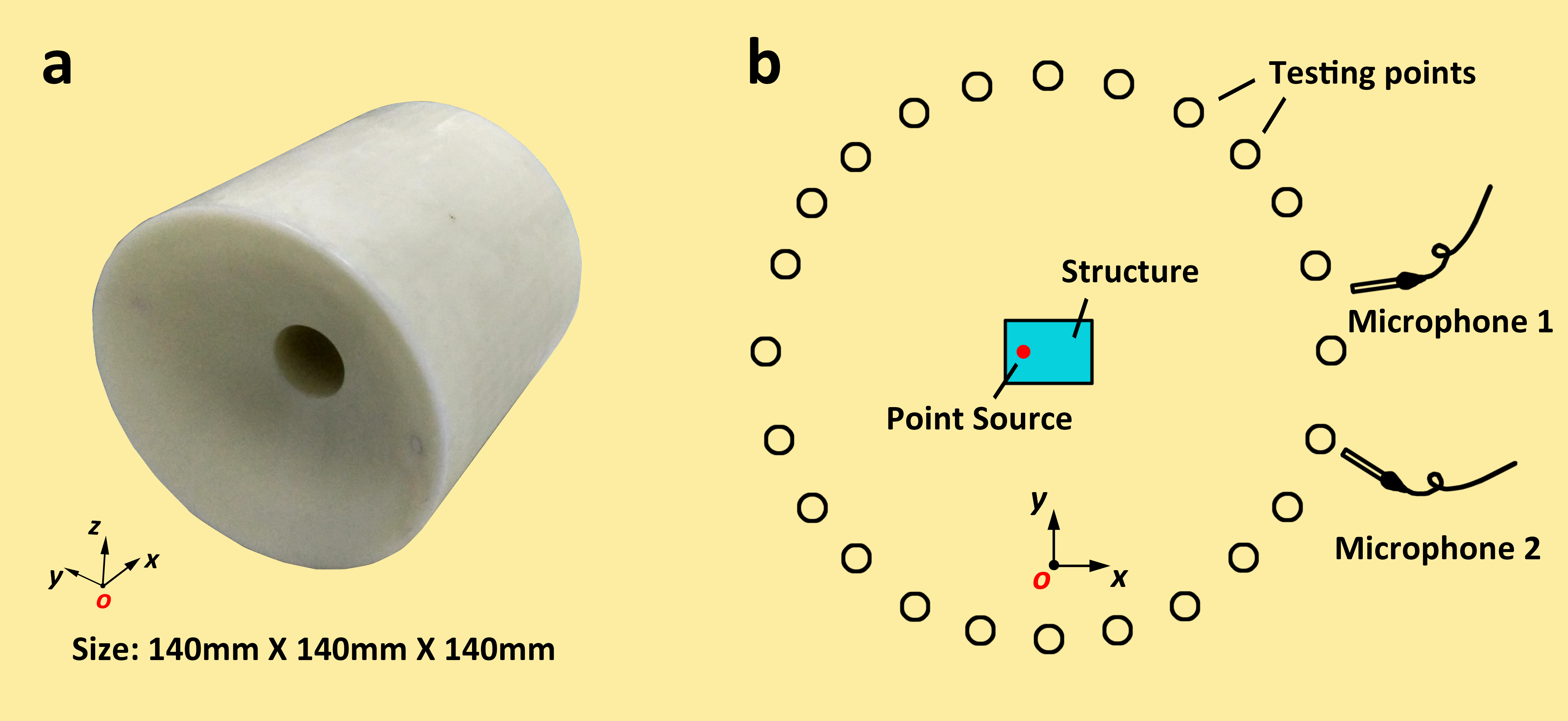
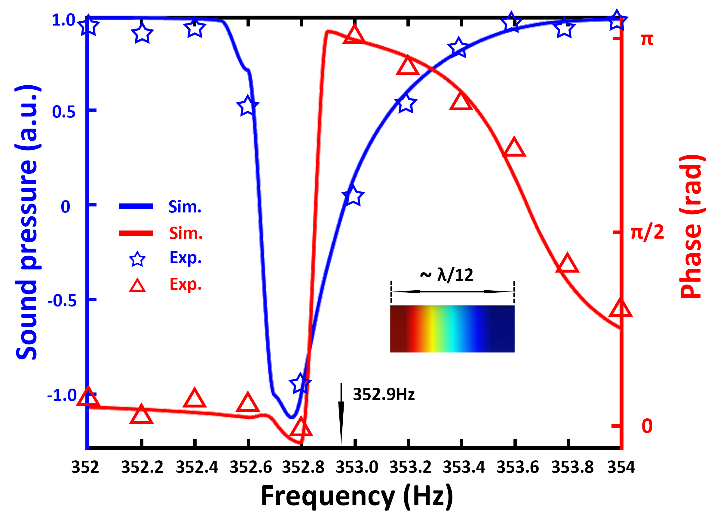
Figure 3 shows the simulated results and measured data of the amplitude and phase differences on the two openings of the artificial structure with the sound pressure distribution inside the cylindrical tube at the resonant frequency being inserted. From the result, we can obtain that the amplitude difference is zero and the phase difference is at around 352.9Hz, which is the frequency to realize a dipole-like directivity as implied by the black arrow. And the corresponding (i.e., ) and (i.e., ). Good agreements between the measurement data, the simulation results and the theoretical prediction prove that our artificial structure can convert a monopole source to radiate sound waves like a dipole source in subwavelength dimension.
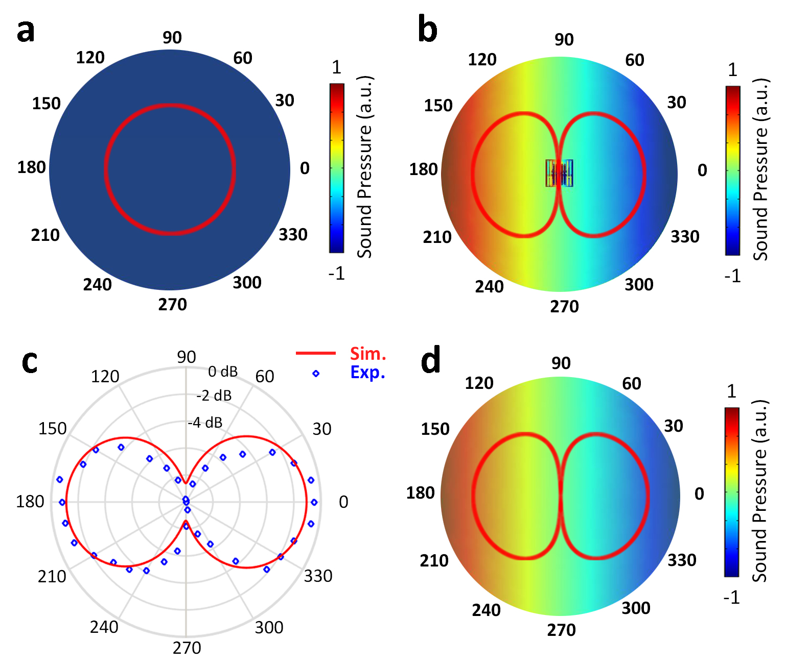
Figures 4(a) and 4(b) display the simulated spatial distribution of pressure fields for sound radiated from low-frequency monopole sources with and without the designed artificial structure respectively. Figure 4(a) shows that in the absence of any artificial structure, the monopole source radiates sound equally in all directions as expected. In the presence of our designed structure, the original radiation field produced by the monopole source is converted into a dipole with near-unity efficiency, as shown in Fig.4(b), revealing the effectiveness of our scheme of generating directional radiation for low-frequency sound.
Figure 4(c) shows the simulated results and the measured data of the directivity. Measured results agree well with the simulated ones, with both proving that our artificial structure can convert a monopole source to radiate sound waves like a dipole source in subwavelength dimension.
For a better comparison, we also plot the radiation of a simple dipole in free space in Fig.4(d). The artificial dipole realized by the combination of a single monopole source and the subwavelength structure physically avoids the destructive interference of the two sources with opposite phases in a subwavelength interval. The radiation efficiency is 2.3 of the traditional dipole consisting of two out-of-phase monopole sources separated at a distance equal to the dimension of the structure . This amplification is beneficial from our structure that supports hybrid resonances in the tubes.
·
Discussion
We have demonstrated the conversion of acoustic monopole source to dipole in a subwavelength source space via numerical simulations and experimental measurements. The whole structure has its every dimension at an order smaller than the sound wavelength, however, the radiation efficiency is up to 2.3 of the direct radiation of a dipole consisting of two out-of-phase monopoles seperated at a subwavelength distance equal to the dimension of our structure.
The design is beneficial from the coupling resonances of sound waves in our structure. While it is expected from the known properties of acoustic resonances to provide phase shift in limited spaces C. and U. (1968), our structure has used a configuration of spiral tubes that enable the resonances to be effectively excited in a way that the coupling of sound energy in the structure leads to the desired phase delay for the efficient radiation of directional sound waves from an omnidirectional monopole enclosed by our structure that has a subwavelengh dimension as a whole.
The scheme proposed here only works within a narrow frequency band due to the mechanism of resonances, but the narrow-band sound source is also an important category of acoustic speakers/transducers that traditionally was associated with the resonances of the crystal of the transducers, though it is of interest to have a directional radiation of broad-band sources by a subwavelength source that we pursue here. The results inspire the further study of converting monopole to arbitrary multipoles or even to a desired directional beam in subwavelength dimension with much higher radiation efficiency. Besides, the directional radiation of low frequency sound is also important to help understand the phenomena in nature such as for the dolphin to use directional sound for long-range communication even with its subwavelength vocal source. Our scheme takes the advantages of simpleness and compactness compared with existing traditional methods, which may open an avenue to solve the long-existing problem of omnidirectional radiation in low frequency in subwavelength dimension.
Acknowledgements.
This work was supported by a start-up fund of the University of Mississippi, the National Natural Science Foundation of China (Grant Nos. 11634006 and 81127901), and A Project Funded by the Priority Academic Program Development of Jiangsu Higher Education Institutions.References
- C. and U. (1968) Morse P. M. C. and Ingard K. U., “Theoretical acoustics,” Princeton university (1968).
- Russell et al. (1999) Daniel A. Russell, Joseph P. Titlow, and Ya-Juan Bemmen, “Acoustic monopoles, dipoles, and quadrupoles: An experiment revisited,” American Journal of Physics 67, 660 (1999).
- Li et al. (2015) Yong Li, Xue Jiang, Bin Liang, Cheng Jianchun, and Likun Zhang, “Metascreen-based acoustic passive phased array,” Phys. Rev. Appl. 4, 024003 (2015).
- Berkhout et al. (2016) A. J. Berkhout, D. de Vries, and Vogel P., “Acoustic control by wave field synthesis,” The Journal of the Acoustical Society of America 93, 2764 (2016).
- Azar et al. (2000) L. Azar, SHi Y., and S. C. Wooh, “Beam focusing behavior of linear phased arrays,” NDT and E International 33, 189 (2000).
- Wang (1992) H.S.C. Wang, “Performance of phased-array antennas with mechanical errors,” IEEE Transactions on Aerospace and Electronic Systems 28, 535 (1992).
- S. and A. (1989) Ebbini E. S. and Cain C. A., “Multiple-focus ultrasound phased-array pattern synthesis: optimal driving-signal distributions for hyperthermia,” IEEE transactions on ultrasonics, ferroelectrics, and frequency control 36, 540 (1989).
- C. et al. (1999) Clay A. C., Wooh S. C., Azar L., and Jiyong Wang, “Experimental study of phased array beam steering characteristics,” Journal of Nondestructive Evaluation 18, 59 (1999).
- Zhao et al. (2013) Jiajun Zhao, Baowen Li, Zhining Chen, and ChengWei Qiu, “Redirection of sound waves using acoustic metasurface,” Appl. Phys. Lett. 103, 151604 (2013).
- Li et al. (2014) Yong Li, Xue Jiang, Ruiqi Li, Bin Liang, Xinye Zou, Leilei Yin, and Jianchun Cheng, “Experimental realization of full control of reflected waves with subwavelength acoustic metasurfaces,” Phys. Rev. Appl. 2, 064002 (2014).
- Liang and Li (2012) Zixian Liang and Jensen Li, “Extreme acoustic metamaterial by coiling up space,” Phys. Rev. Lett. 108, 114301 (2012).
- Zhu et al. (2016) Xuefeng Zhu, Kun Li, Peng Zhang, Jie Zhu, Jintao Zhang, Chao Tian, and Shengchun Liu, “Implementation of dispersion-free slow acoustic wave propagation and phase engineering with helical-structured metamaterials,” Nature Commun. 7, 11731 (2016).
- Jiang et al. (2016) Xue Jiang, Likun Zhang, Bin Liang, Xinye Zou, and Jianchun Cheng, “Radiation directivity rotation by acoustic metamaterials,” Appl. Phys. Lett. 107, 093506 (2016).